
Secure Workload and Kubernetes Security - Deep Dive
Kubernetes Security - whitepaper
Cisco Secure Workload – Solution Overview
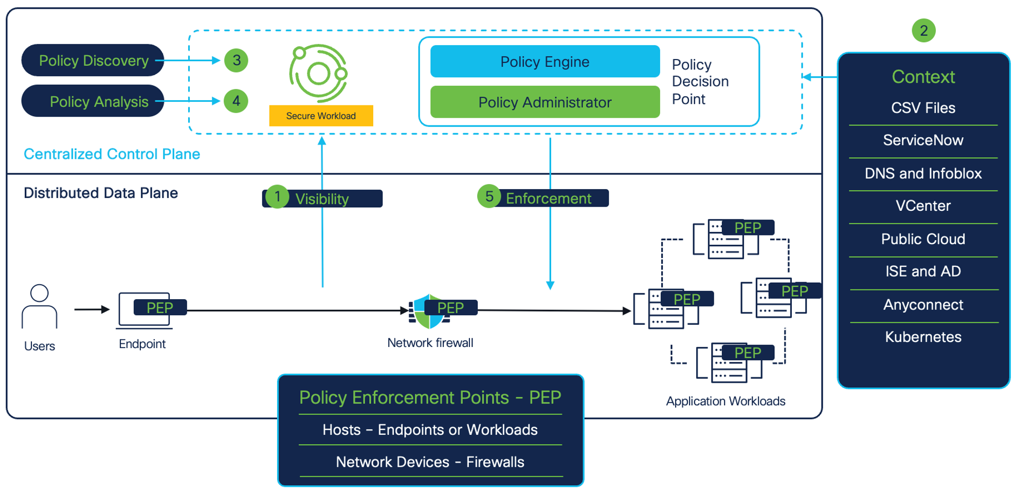
Figure 1: Solution Overview
Cisco Secure Workload is a holistic security platform that delivers zero trust microsegmentation and other workload security capabilities through both agent-based and agentless approaches across a hybrid multicloud workload environment. It enables:
- Full visibility into applications and workload environment. The visibility includes:
- Contextualized network communications within the confines of datacenter or public cloud, and beyond.
- Vulnerable software packages installed on the application workloads (CVEs).
- Runtime forensics and processes level activity on the application workloads (MITRE TTPs).
- Automatic discovery and analysis of policies to achieve zero trust microsegmentation for business applications. The policy analysis can be done without the need to do policy enforcement.
- Enforcing and monitoring policy compliance across different policy enforcement points. Enforcement points can be in the form of:
- Host firewalls like Linux Iptables or Windows Firewall (on bare metal, virtual machines in private or public cloud, or Kubernetes/Openshift clusters or DPUs)
- Cloud built-in firewall controls like AWS Security Groups, Network Security Groups, and GCP network firewall for public cloud workloads.
- Network devices like load balancers and network firewalls.
Secure Workload and Kubernetes Security– Architecture
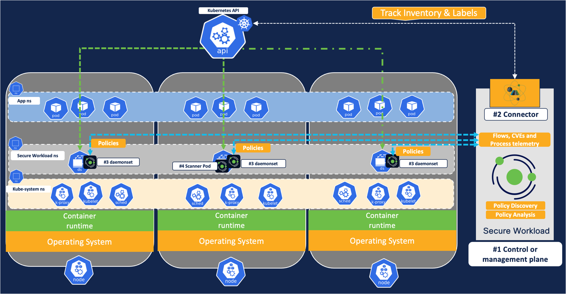
Figure 2: Architecture
From the architecture standpoint, there are four major components of this deployment.
- Control plane or management plane -This can be on an on-prem Secure Workload cluster or a SaaS hosted Secure Workload tenant. This is where the workload visibility telemetry is processed and policies are defined, validated, and monitored.
- Secure workload orchestrator/connector – The connector is created on the management plane and it interacts with Kubernetes cluster APIs for EKS/AKS/GKE/Openshift/Unmanaged Kubernetes to provide gather additional telemetry about pods and service metadata like pod ids, annotations or labels/tags etc.
- Kubernetes Daemonset – Daemonset ensures that the Secure workload agent (or pod) is running at all times on each Kubernetes or Openshift node. The functions of daemonset include:
- Flow visibility: node agent or the daemonset allows the ability to monitor any network flows on the Kubernetes cluster and report it back to the cluster. This can be run in a conversation mode or detailed mode.
- In conversation mode, the agent summarized the flow observations every 15 seconds and reported them back to the control plane at intervals of 15 seconds.
- In detailed mode, the agent captures every packet on a given node (originated in the node namespace or pod namespace) and reports it back to the control plane every second.
- Policy Enforcement: This node agent also allows the ability to program firewall rules on each node to restrict a free flow lateral movement among the pods, nodes, or the cluster boundary.
- Flow visibility: node agent or the daemonset allows the ability to monitor any network flows on the Kubernetes cluster and report it back to the cluster. This can be run in a conversation mode or detailed mode.
- Vulnerability Scanner - Optionally, if you enable vulnerability scanning then scan feature is activated on one of the pods on the Kubernetes nodes. This scanner monitors every Linux container image running on the Kubernetes/Openshift cluster and reports the associated CVEs to the management plane.
Use Cases
Use Case #1 Visibility into Kubernetes inventory and network communications
Workload Inventory
Secure Workload’s Kubernetes connectors or orchestrators provide real-time monitoring of every pod or service running the Kubernetes or Openshift cluster. Any change in the Kubernetes inventory is continuously monitored and updated, for example – when a new pod is added to a cluster, or a new label, a key-value is added to an existing pod, the inventory change is reflected in near real-time on the Secure Workload.
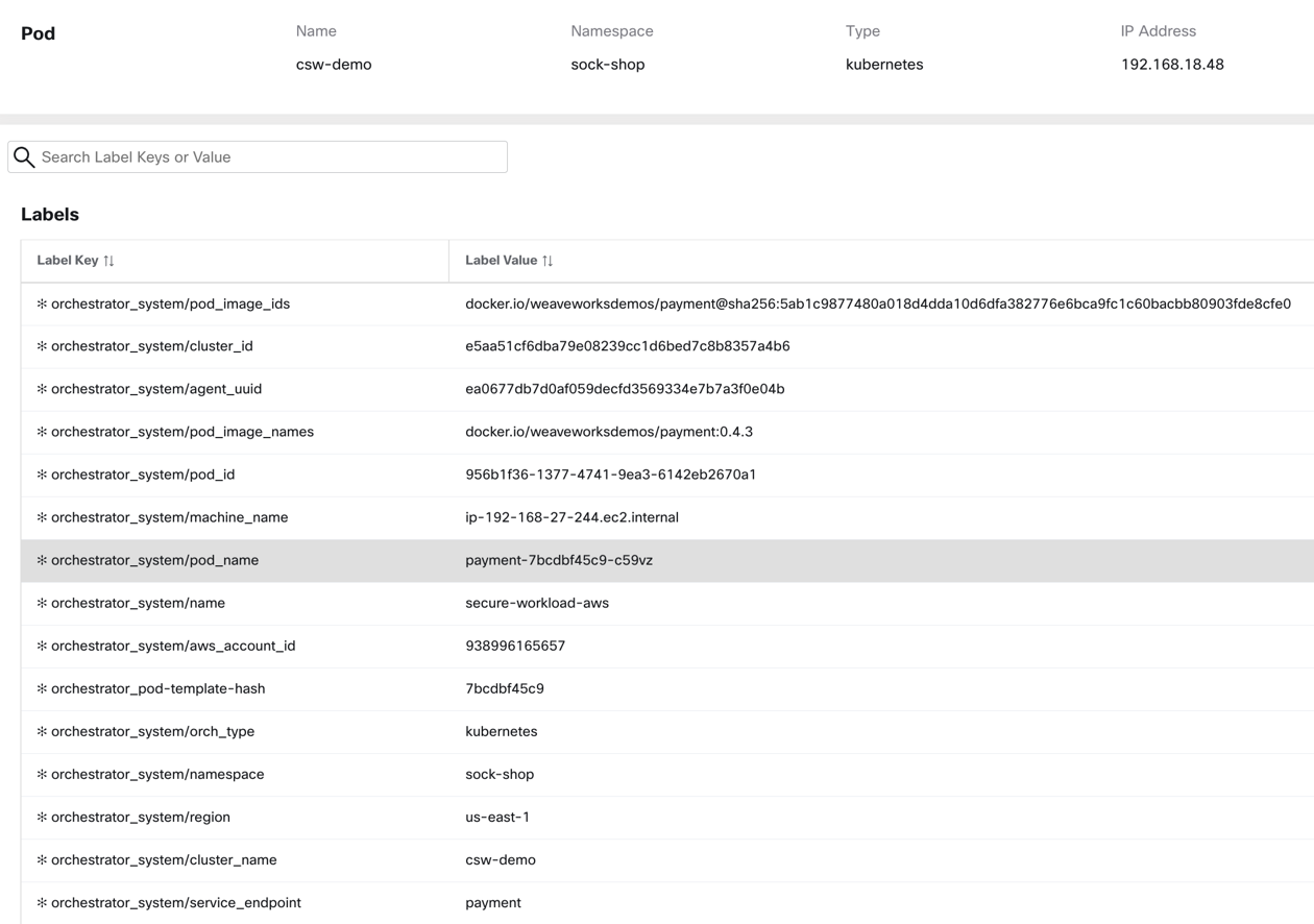
Figure 3: A sample Kubernetes pod profile with label metadata
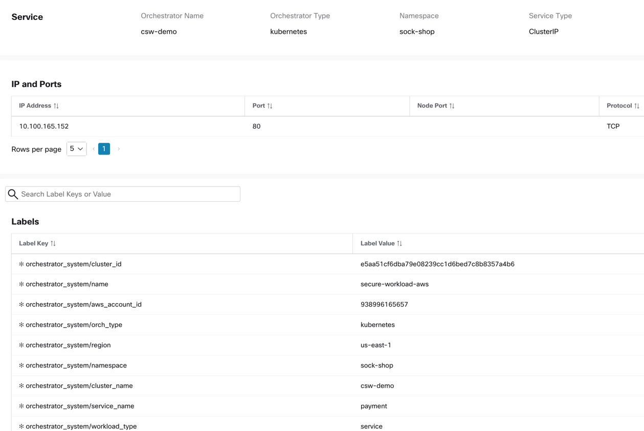
Figure 4: A Kubernetes sample service profile with label metadata
The dynamic monitoring of pod or service IP addresses and associated metadata allows the building of dynamic policy objects on Secure Workload, and hence supporting the creation of dynamic microsegmentation policies (more details about policies are further down in this document).
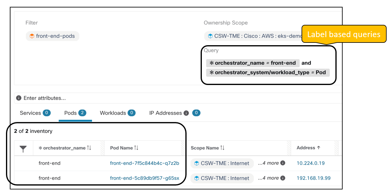
Figure 5: An Inventory filter based on Pod metadata
Network flows
Secure Workload node agent or daemonset provides real-time network flow visibility. The flows are granular down to the TCP/UDP flags, bytes, and packet count exchanged over network connections. These flows are enriched further by the label or metadata from the Kubernetes cluster inventory. The network communications or flows happening on a given Kubernetes cluster can be broadly of the following types:
- Pod to pod network flows – (Intra node or Inter node pods)
- Direct pod to pod network communications
- Pod to pod communications via ClusterIP Kubernetes service.
- External IP to pod communications (via NodePort or LoadBalancer Kubernetes Service)
- Pod to external communications
Secure workload agent/pod running on each node captures the network flows at two different levels - from the pod network interfaces and the node network interfaces.
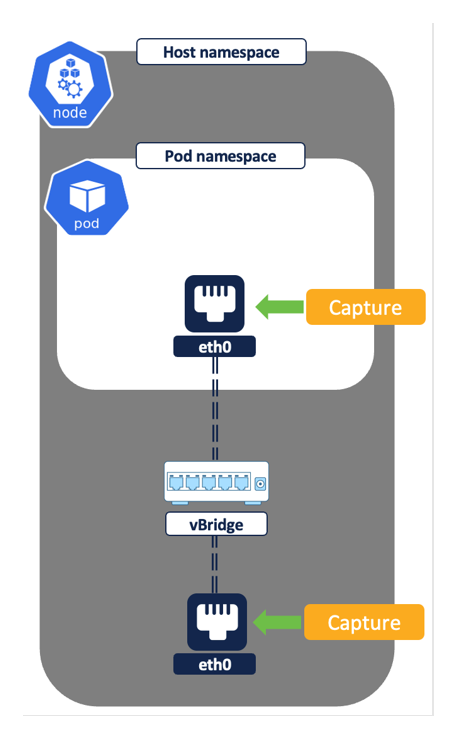
Figure 6: Flow capture on network interfaces
We will now look at how the secure workload agent or daemonset captures and logs a different set of network flows depending on the type of network communication.
Direct pod to pod flows – A direct pod to pod connection between two pods may happen on the same Kubernetes node i.e intra node or different nodes i.e. inter node. The reported flows will vary depending on the type of connection.
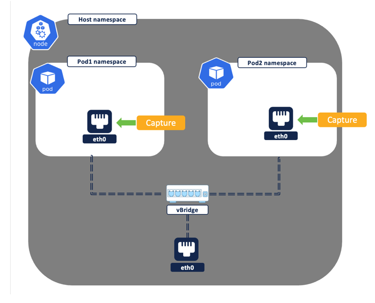
Figure 7: Intra node - pod to pod flow
- Intra node – Both source and destination pod are running on the same node.
- A single flow with the source as pod1 IP and destination of pod2 IP is logged. Though the same network flow is captured at both the source and destination pod network interface by the Secure Workload node agent, the two flows get deduped and reported by the platform as a single flow.
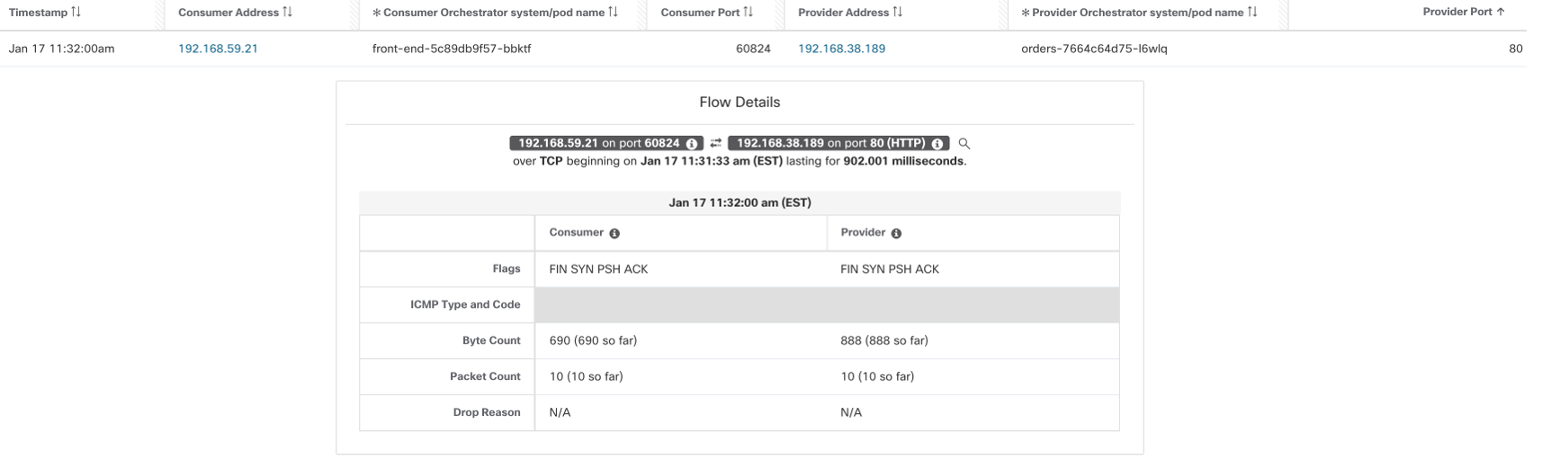
Figure 8 - Intra node - captured pod to pod flow
- Inter node (Figure 9) – The source and destination pod is located on different Kubernetes nodes.
- The first flow, in Figure 10, is captured at the source pod network interface. The flow source is pod1 IP and the destination is pod2 IP.
- Depending on the CNI networking (direct routing or overlay mode) in use, a second flow may or may not get logged. For example-
- Direct routing – If the pod CIDR is routable then there is no additional flows to log. The packets traverse from source to destination without any modifications, so the same flow, when captured at Node1, Node2, and Pod2 network interfaces, will get deduped as a single flow above.
- Overlay tunnel mode:
- VXLAN or Geneve – A UDP tunneled flow is logged with the source as node1 IP and the destination as node 2 IP. This UDP flow encapsulates the actual packet.
- IPIP – A TCP flow record with source as node1 IP and destination as node2 IP is logged.
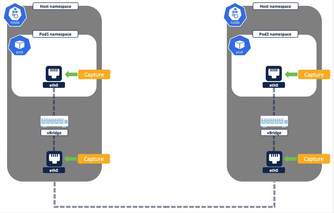
Figure 9: Inter node - pod to pod flow
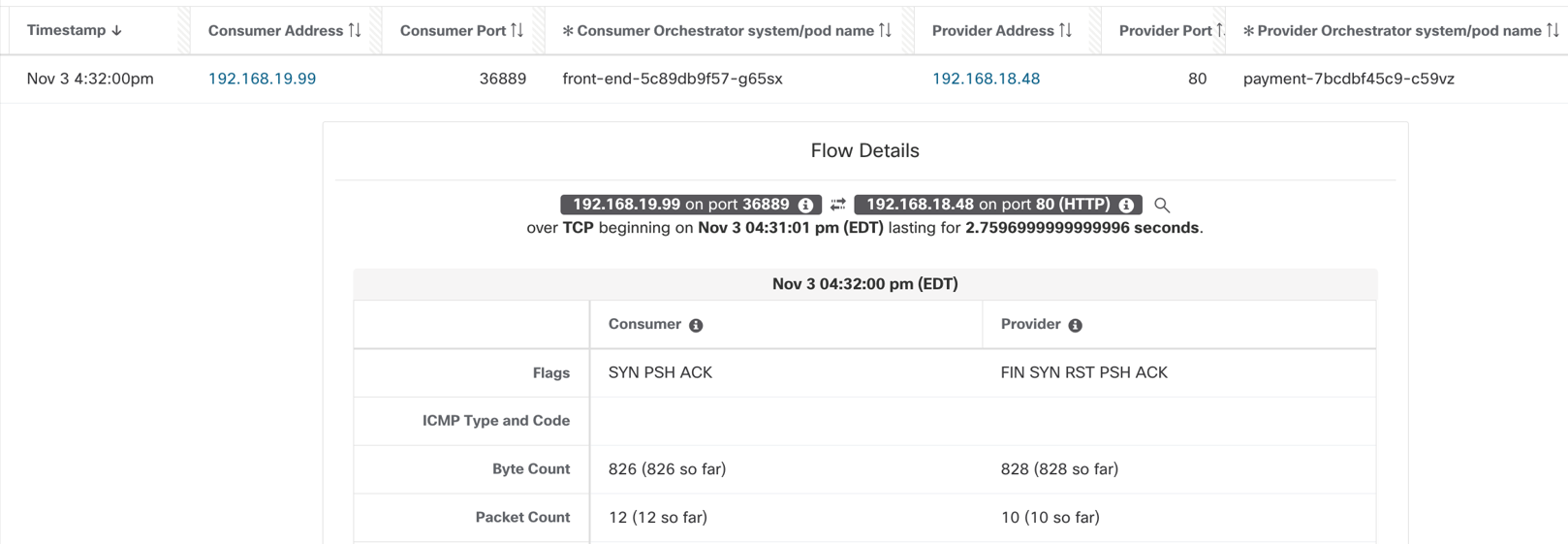
Figure 10: Inter node - captured pod to pod flow
Pod to pod flows via Kubernetes service –The pod to pod connection can happen via a Kubernetes service (type ClusterIP). The flow reporting will vary depending on the type of connection.
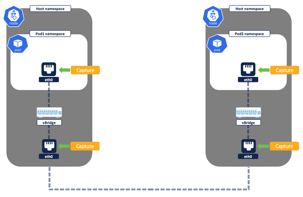
Figure 11: Pod to pod flows
- Intra node – Both source and destination pod are on the same node.
- First network flow will be reported with source as Pod1 IP and destination as ClusterIP service IP. This flow is captured at the source pod network interface.
- After the flow leaves Pod 1network interface, it undergoes DNAT in the node or host namespace to Pod 2 IP as the destination address.
- The second network flow is capured at Pod2 network interface. The flow will be reported with the source as Pod1 IP and the destination as Pod2 IP.
- The two flows will show up as ‘Related’ flows.
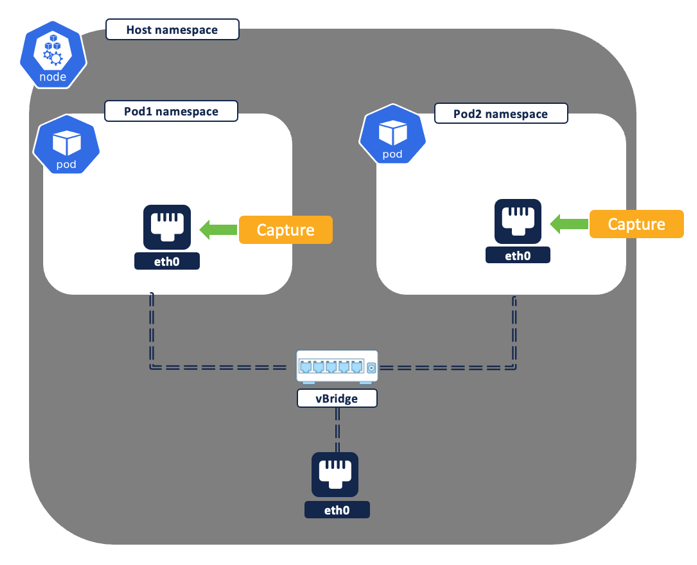
Figure 12: Intra node - pod to pod via service
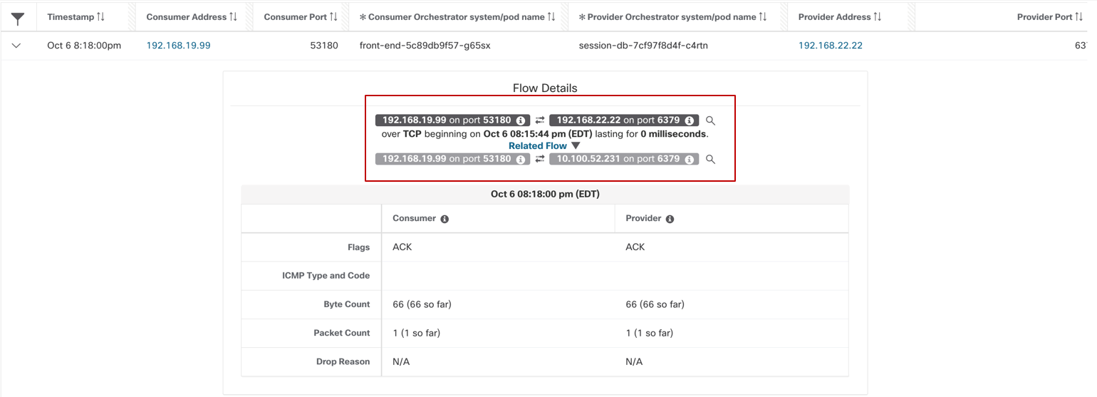
Figure 13: Pod to pod via service - intra node
- Inter node - The source and destination pod are on different nodes.
- First network flow will be captured with source as Pod1 IP and destination as Service IP. This is captured at the source Pod1 network interface.
- After the flow leaves the Pod1 network interface, it undergoes DNAT in the host namespace. The service IP is translated to Pod 2 IP as a destination. The second network flow is captured at node1 network interface. The flow will be reported with the source as Pod1 IP and destination as Pod2 IP and will show as a related flow to the previous flow.
- Depending on the CNI networking (direct routing or overlay mode) in use, a third flow may get logged. For example -
- Direct routing – If the pod CIDR is routable then there is no additional flow to log. The packets traverse from source to destination without any modifications, so the same flow, when captured at Node1, Node2 and Pod2 network interfaces, will get deduped as single flow above.
- Overlay tunneling mode:
- VXLAN or Geneve – A UDP tunneled flow is logged with source as node1 IP and the destination as node 2 IP. This UDP flow encapsulates the actual packet.
- IPIP – A TCP flow record with source as node1 IP and destination as node2 IP is logged.
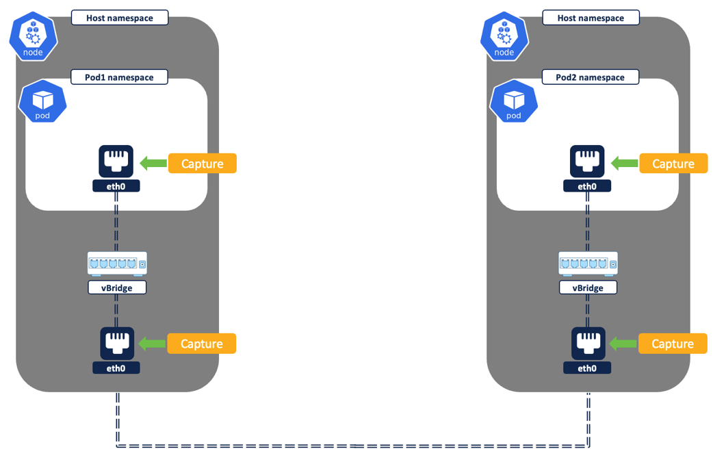
Figure 14: Pod to pod - inter node
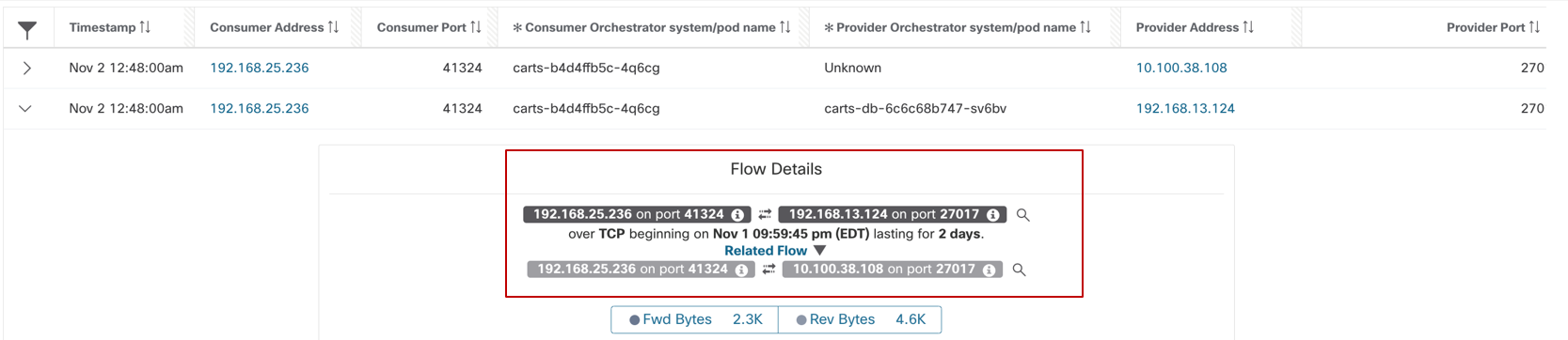
Figure 15: Pod to pod via service - inter node
External IP to pod IP flows – (Figure 16) The pods are exposed to any external IP(outside cluster) via NodePort or Loadbalancer service (among many other, we will cover these two in this document). Both NodePort and Loadbalancer Kubernetes Service are essentially the same, the only difference is that with Service Type Loadbalancer you get additional automation to create an external loadbalancer in Public cloud. The external loadbalancer frontends and distributes connections to the K8s cluster nodes. From flow reporting perspective, in both scenarios, two sets of flows are captured for any external IP to pod communications.
- The flow source as External IP and destination as Node IP:NodePort is captured and logged from the Node’s network interface (Figure 17).
- The traffic undergoes Source NAT and Destination NAT.
- The source is natted to node IP.
- The destination IP and port (i.e. Kubernetes service of type loadbalancer or Nodeport) is translated to Pod IP and Pod port.
- After this translation, a second flow with source as Node IP and destination as Pod IP:PodPort is captured at the Pod network interface (Figure 18).
- A third flow may get logged if the destination pod is not running on the same node where the connection lands, the nature of flow depends on the CNI networking.
NOTE:
For ease of understanding, consider the pod to be running on same node as incoming flow.
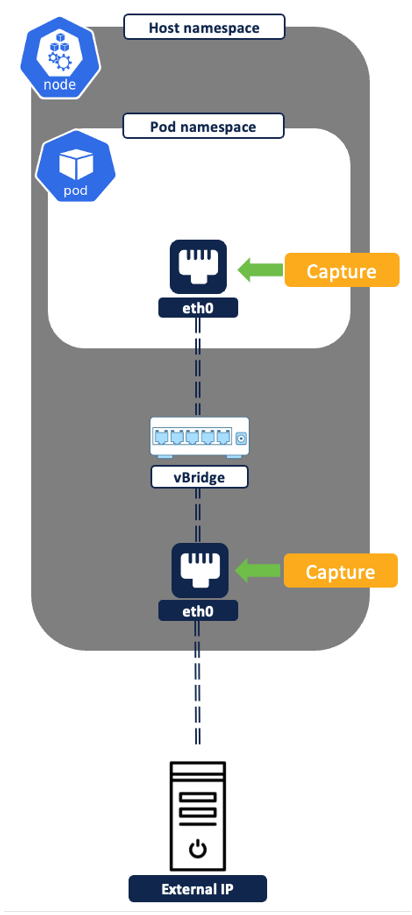
Figure 16: External IP to pod IP flows
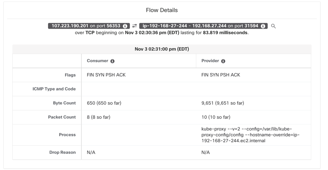
Figure 17: External IP to node IP: NodePort
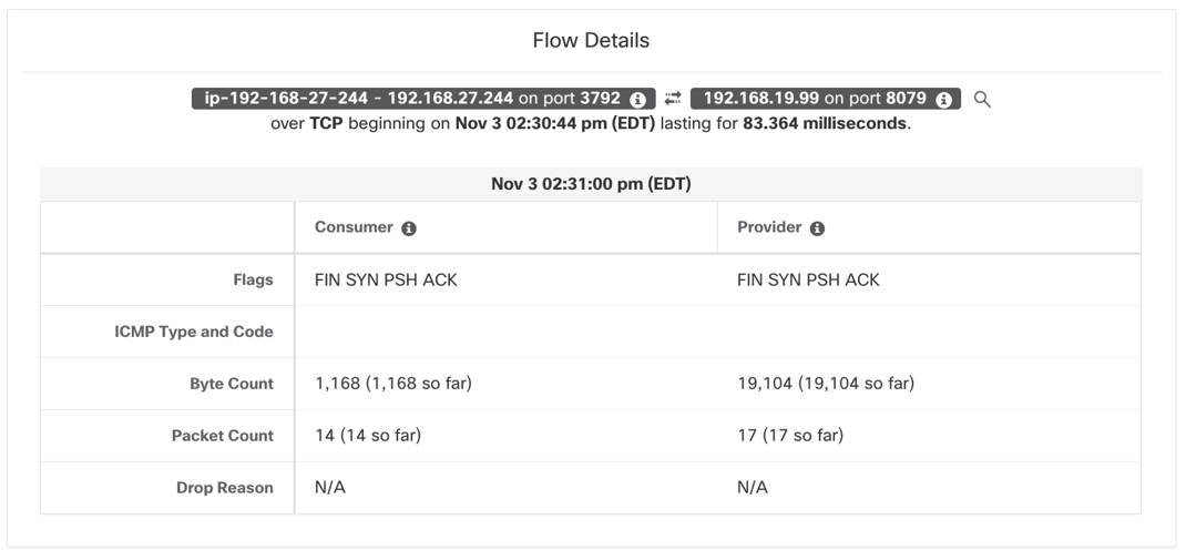
Figure 18: NodeIP to PodIP: PodPort
Pod to external IP flows – Two sets of network flows are reported, one from the source pod network interface and the second from the node network interface.
- First flow is captured and logged from the source Pod network interface. The flow source is Pod IP and destination as External IP.
- Flow undergoes source NAT translation in the host namespace before it leaves node network interface. The second flow is captured and logged from the node network interface, with flow source as Node IP and destination as external IP.
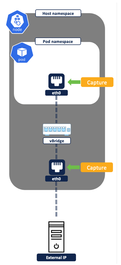
Figure 19: Pod to External IP Flows
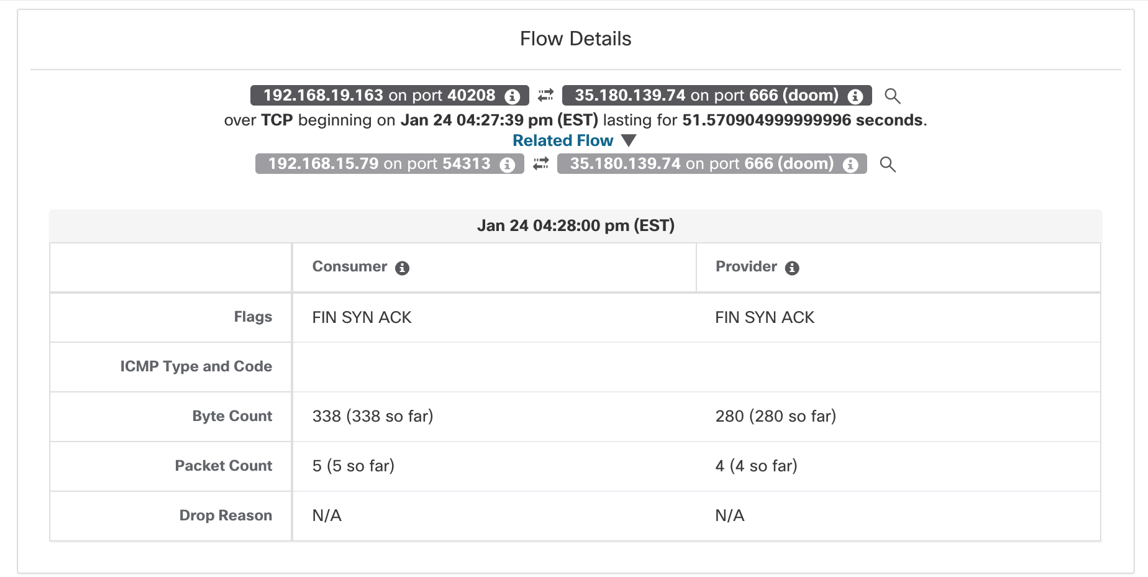
Figure 20: Pod to external IP communications
Use Case #2 Zero trust microsegmentation for Kubernetes
Zero trust microsegmentation journey involves a series of steps beginning with a scope design, policy creation, policy analysis/validation to policy enforcement and policy compliance monitoring. Secure Workload provides the end to end frame work to facilitate each of these steps.
Step 1: Scope Design – Scope in the world of Secure Workload is a construct that allows you to group a set of workloads. For example, a set of workloads belonging to a business application can be mapped to one scope. The Secure Workload admin can use scopes to independently manage policy lifecycle for given group of workloads or delegate RBAC to workload owner group to manage the policies in an controlled manner without affecting other applications.
There are two broad scope design approaches that you can follow when it comes to Kubernetes environment.
- Single scope design - If you want to manage policies for an entire Kubernetes cluster or a group of similar Kubernetes clusters together then, one or more clusters can be grouped into a single scope.
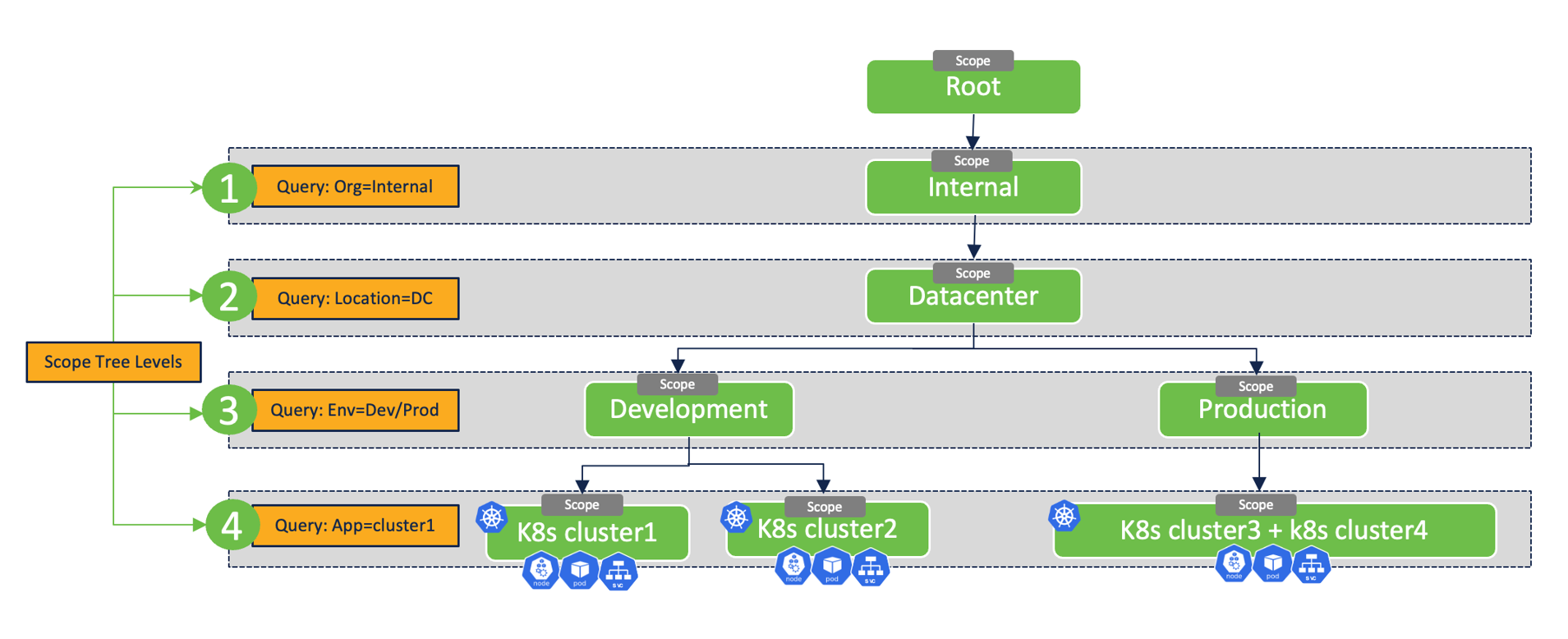
Figure 21: Single scope design
- Split scope design - If multiple applications are running on the same Kubernetes cluster and the requirement is to manage policies for each application independently or separately then:
- You can map the Kubernetes cluster inventory to a parent scope.
- The subset of pods and services (that belong to a certain business applications) can be mapped to a separate child scope. As an example – if each application is confined to a dedicated Kubernetes namespace, then multiple child scopes can be created based on Kubernetes namespaces.
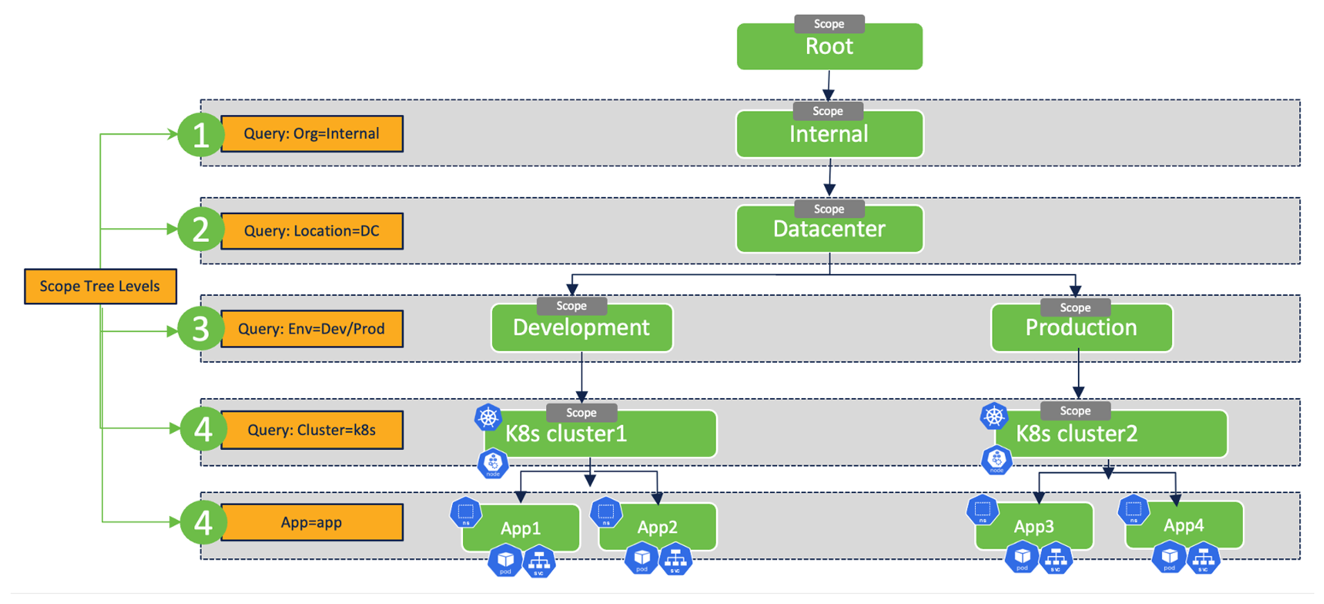
Figure 22: Split scope design
Step 2: Policy discovery – Secure Workload facilitates two approaches to policy creation.
- Manual approach - via GUI or APIs or via infrastructure as code tools like terraform or ansible.
- Automated policy discovery - The Secure Workload policy discovery engine provides the ability to automatically discover segmentation policies. The discovery tool relies on workload inventory and flow data discussed in use case #1.
Step 3: Analyze and validate policies – Real-time policy analysis tool allows you to define policy versions and analyze them against live traffic from the Kubernetes workloads to look for any unexpected connection allows or blocks. The policy analysis doesn’t require the policies to be enforced on the Kubernetes cluster.
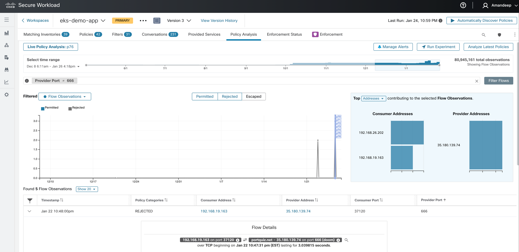
Figure 23: Policy Analysis
Step 4: Enforce policies on the K8s nodes – Depending on the policy intent, Secure Workload’s policy engine will do the translation to a set of concrete and container level rules.
- The concrete rules are programmed to Kubernetes node namespace iptables.
- The container rules are programmed to specific pod’s namespace iptables.
Let’s try and understand this using some example policies and how they are translated by Secure Workload’s policy engine to the pod and node level rules:
-
Direct pod to pod flows (without clusterIP service) –
-
Example policy (Figure 26) - Allow payment pod to connect to user-db pod on TCP port 27017.
-
Pod/Container rules:
- Payment pod rule (Figure 27): EGRESS: Allow payment pod to userdb pod on TCP port 27017.
- Userdb pod rule (Figure 28): INGRESS: Allow payment pod to userdb pod on TCP port 27017.
-
Node/Concrete Rules: There are no filtering rules programmed at the node level corresponding to this policy. By default, the CNI takes care of allowing the necessary routing and flows at the node level. Any inter-node pod-to-pod traffic is allowed by allow all ‘forward’ chain iptables rules.
-
-
NOTE (Payment Pod Rule):
That the source IP is “Any”, that basically implies any IP address or interface that belongs to payment pod (indicated by Pod ID field). You could also hard-code the policy to a specific network interface IP if frontend pod has multiple network interfaces.
NOTE (Userdb Pod Rule):
That the destination IP is “Any”, that basically means any IP address or network interface that belongs to orders pod. You could also hard-code the policy to specific network interface IP if frontend pod has multiple network interfaces.
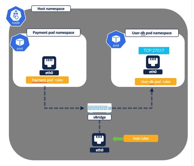
Figure 24: Pod to pod flow - Intra node
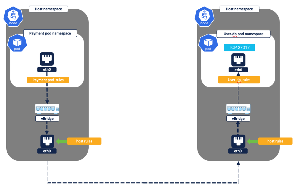
Figure 25: Pod to pod flow - Inter node
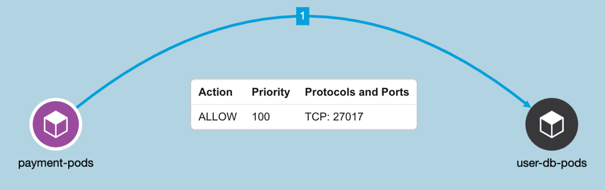
Figure 26: Example Policy
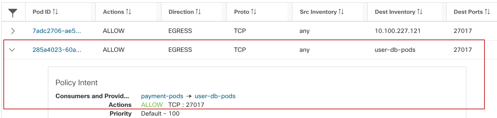
Figure 27: Payment pod rule
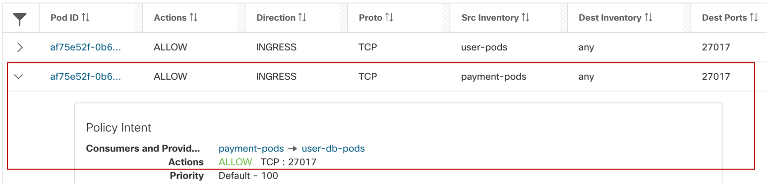
Figure 28: Userdb pod rule
- Pod to pod flow via ClusterIP kubernetes service
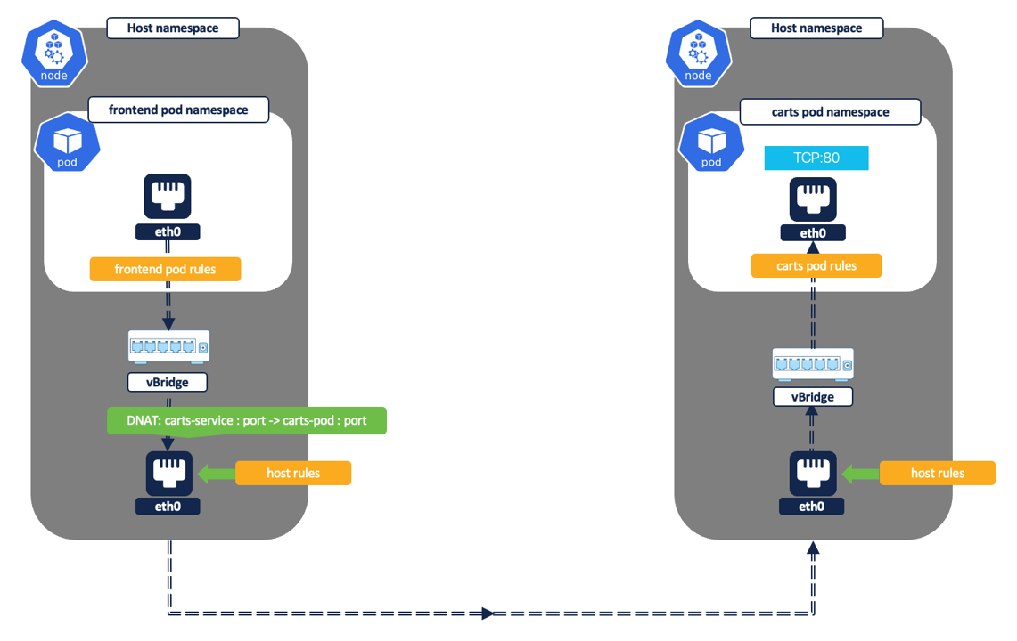
Figure 29: Pod to pod via ClusterIP service
Example policy - Allow frontend pod to connect to carts service on TCP port 80.
In this example, let’s assume that service IP is 10.100.135.136 and carts pod is also listening on TCP port 80.
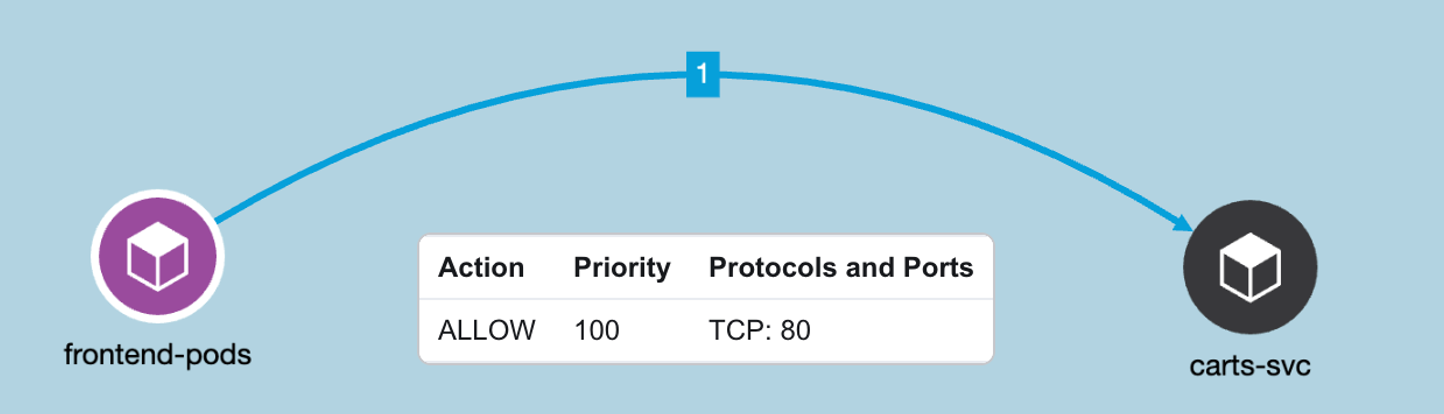
Figure 30: Example Policy - Allow frontend pod to connect to carts service on TCP port 80
- Pod/Container rules:
- Frontend pod rules- EGRESS: Allow frontend pod to carts service on TCP port 80.
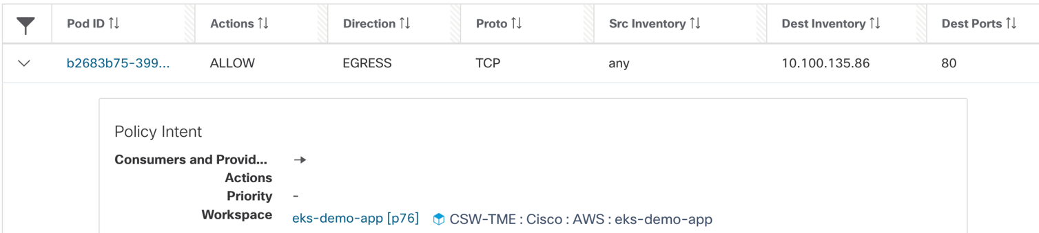
Figure 31: Frontend pod rules
NOTE:
That source IP is “Any”, that basically means any IP address or interface that belongs to frontend pod. The destination is carts clusterIP service address.
- Carts pod rules - INGRESS: Allow frontend pod to carts pod on TCP port 80
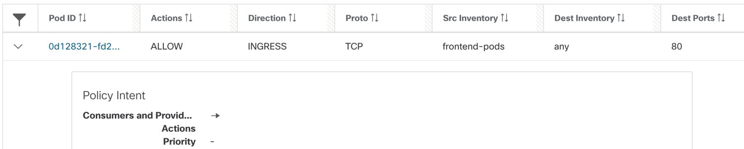
Figure 32: Carts pod rules
NOTE:
The destination IP is “Any”, that basically implies all IP addresses or interfaces that belongs to carts pod. The destination IP is DNAT’ed to carts pod IP in the node namespace. Hence, when the traffic is ingressing the carts pod, the rule should allow destination as carts pod IP. Even though, the carts pod IP is not specified in the original intent policy, the rule is auto-generated by the secure workload policy engine.
Node/Concrete level rules: There are no filtering rules progammed at the node level for this policy. By default, the CNI takes care of allowing the necessary routing and flows at the node level. Any inter node pod to pod traffic is allowed by a ‘forward’ iptables rules.
- Healthcheck probes from sourced from node IPs to the pods.
Example policy - Allow Kubernetes healthcheck/readiness probes to frontend pod on TCP port 80.
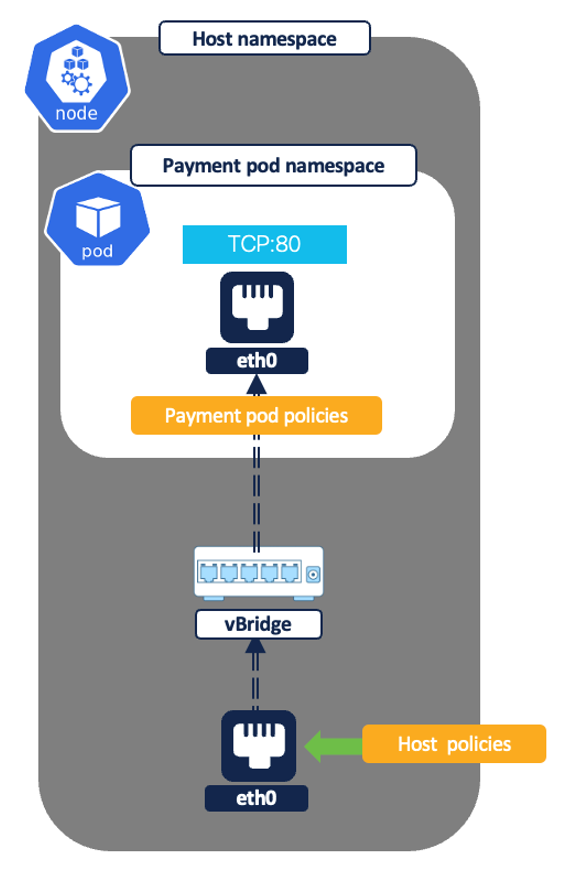
Figure 33: Node to pod - healthchecks
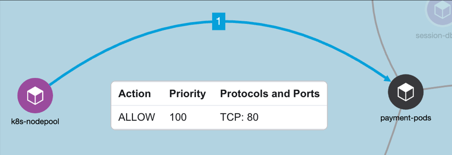
Figure 34: Example Policy - Allow Kubernetes healthcheck/readiness probes to frontend pod on TCP port 80
- Node/Concrete rules:
- Cluster nodes rules- EGRESS: Allow node IP to payment pods on TCP port 80.
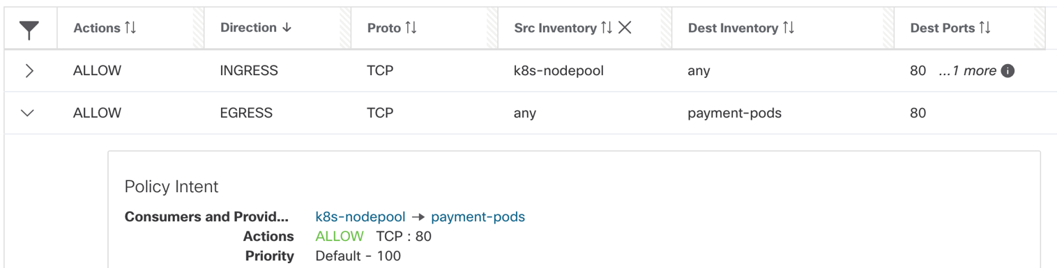
Figure 35: Cluster node rules
NOTE:
The source IP is “Any”, that basically means any IP address or interface that belongs to a given cluster node.
- Pod/Container rules:
- Payment pod rules- INGRESS: Allow node IPs to any IP on TCP port 80.
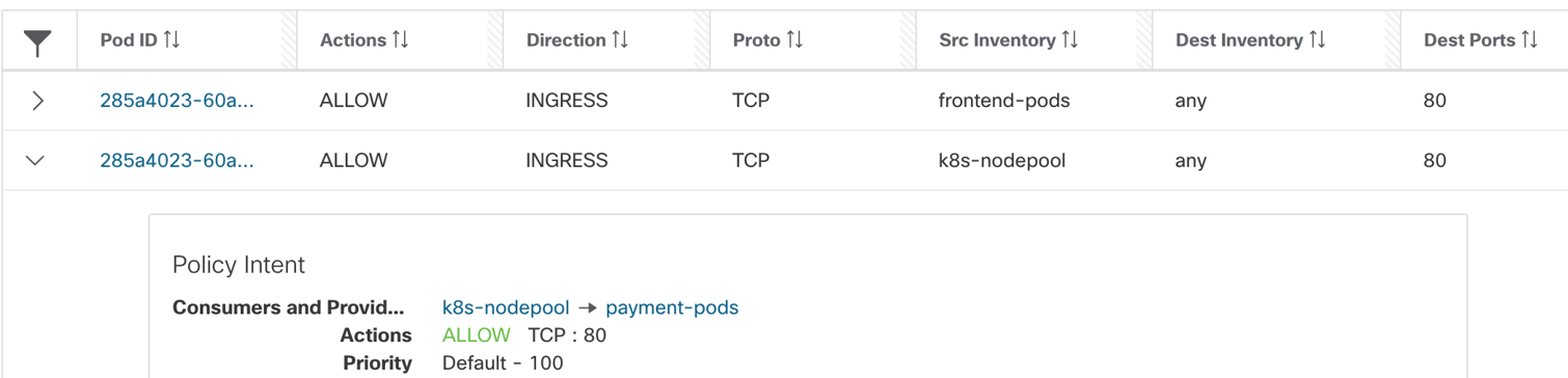
Figure 36: Payment pod rules
NOTE:
The destination IP is “Any”, that implies any IP address or interface that belongs to payment pod.
- External IPs to pod via nodeport or loadbalancer service.
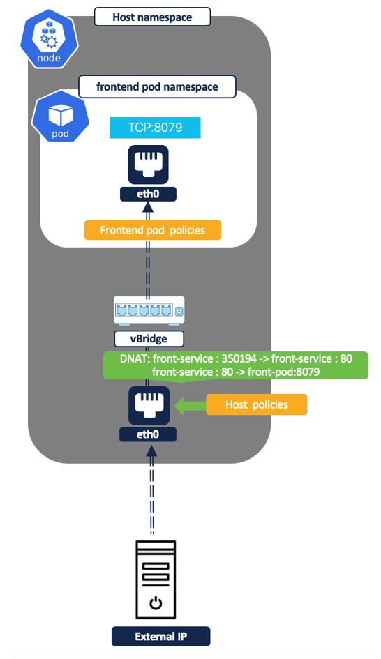
Figure 37: External IP to pod
Example policy - Allow ‘any’ internet user to frontend nodeport service (listening on TCP port 80). Let’s assume the front-end pod is listening on 8079 and nodeport is 31095.
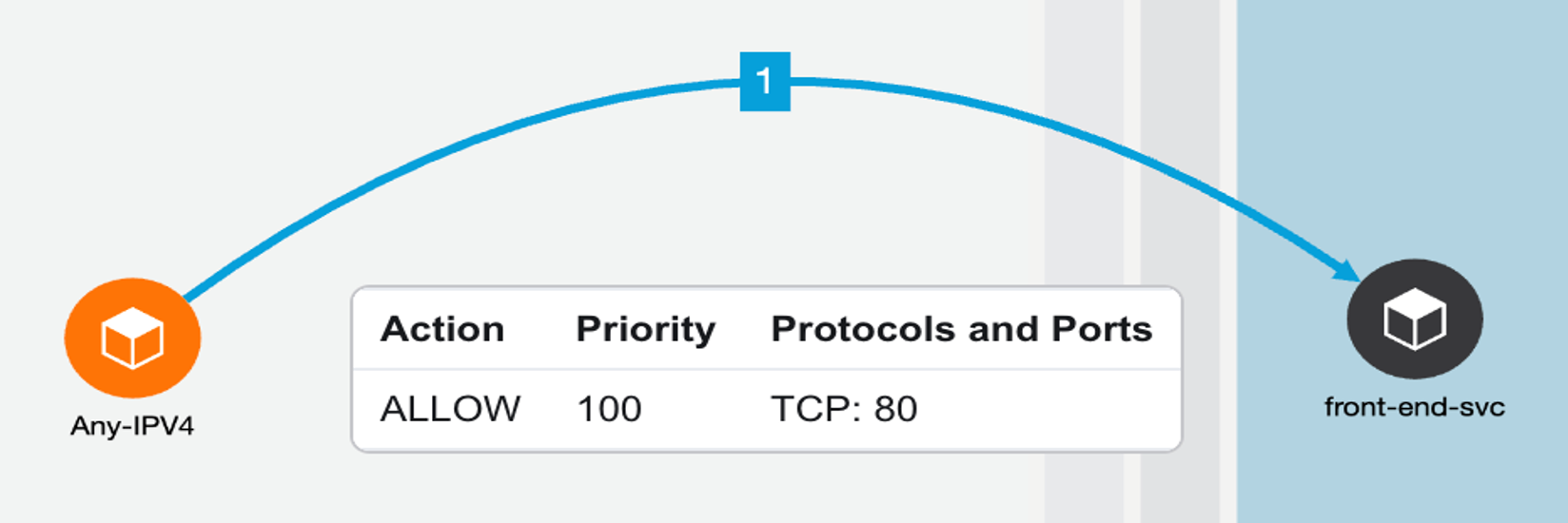
Figure 38: Example policy - Allow ‘any’ internet user to frontend nodeport service
- Node/Concrete level rules:
- On cluster nodes- INGRESS: Allow any IP to node pool IPs on nodeport i.e. TCP port 31095.
- The policy engine auto-generates the pre-routing allow rule for node port.

Figure 39: Policy engine pre-routing allow rule
- Pod/Container rules:
- On frontend pod:- INGRESS: Allow Any IP to frontend pod IP on TCP port 8079.
- The policy engine auto-generates the allow rule for pod port.
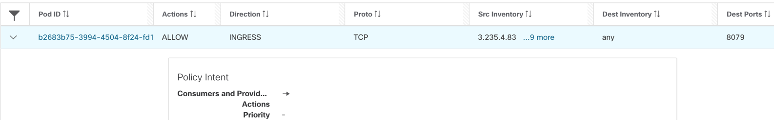
Figure 40: Frontend pod - allow any IP on TCP port 8079
NOTE:
If Kubernetes nodes and application pods/services are mapped to different parent and child Scopes then, make sure the allow rule to frontend service is added on both parent and child scopes.
- Pod to External IP addresses
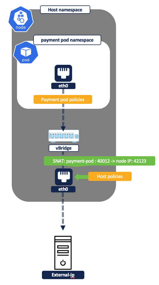
Figure 41: Pod to external IP
Example Policy - Allow ‘frontend’ pod IPs to an external IP on TCP port 666.
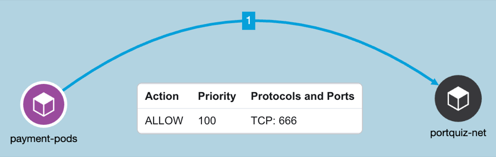
Figure 42: Allow ‘frontend’ pod IPs to an external IP on TCP port
- Pod/Container rules:
- Payment pod rules- EGRESS: Allow payment pod to external IP on TCP port 666.
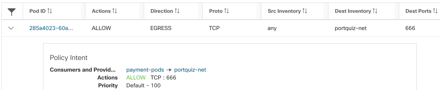
Figure 43: Allow payment pod to external IP on TCP port 666
NOTE:
The source Inventory is “Any”, that basically implies all IP addresses or interfaces that belong to payments pod.
- Node/Concrete level rules: There are no filtering rules programmed at the node level for this policy. At the node namespace, the traffic is source natted to node IP and is allowed by the default ‘forward’ iptables rules i.e. allow-all.
Step 5: Monitor policy compliance - Live policy analysis tool allows you to continue monitoring policy compliance against live traffic from the cluster to look for any unexpected outcome.
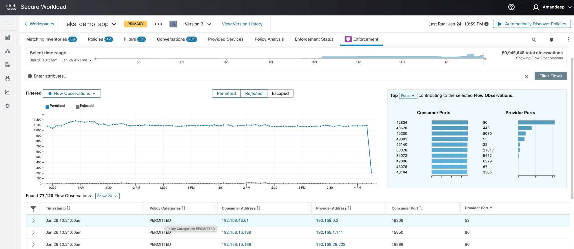
Figure 44: Policy compliance
Use Case #3 Vulnerability scanning for container images
The secure workload scanner pod provides visibility into all the software packages and vulnerabilities associated with container images running on the Kubernetes or Openshift cluster.
How does the vulnerability scanning on Kubernetes cluster work?
- For any onboarded cluster via a connector/external orchestrator, you can optionally enable vulnerability scanning. Once the vulnerability scanning is enabled a scanner pod is spun up on the Kubernetes/Openshift cluster.
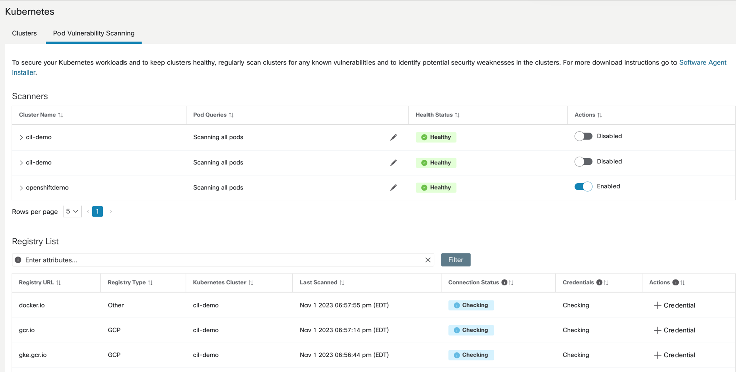
Figure 45: Enable container scanning
NOTE:
Daemonset or agent installation is required for this functionality to be available.
- The scanner pod will scan the list container images running on the cluster and will auto-populate the list of registries where those images are hosted on Secure Workload console.
- If the access to the registry image needs credentials then admin is prompted to add those credentials.
- Once the registry credentials are added, the scanner scans is able to pull the container image from registry and scan for CVEs. The CVE report is then published on the Secure Workload user interface.
NOTE:
Only linux container CVE scanning is supported at the time of publishing of this document.
- The pod CVE attributes can also be used to create policy objects and hence, define CVE risk based segmentation policies.
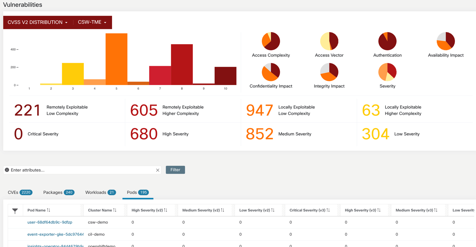
Figure 46: Vulnerability dashboard
FAQs
Question: What node operating systems are supported?
Answer: Both Linux and Windows node OS are supported for a detailed list of OS, refer to the Compatibility Matrix .
Question: Which CNI is supported by Secure Workload agent?
Answer: Secure Workload’s capabilities of flow visibility or policy enforcement are not dependent on any specific CNI functions. All popular CNI types like Calico, Weave, Cillium, Azure CNI, AWS VPC CNI etc. are supported.
Question: Can I enforce CNI based policies along with CSW policies?
Answer: Yes, Secure Workload filter rules take priority. Iptable rules created by CNIs are preserved. NOTE: ‘Preserve rules’ function for agent config is required to be enabled for Kubernetes and Openshift deployments.
Question: Does Secure Workload support Openshift SDN or OVN?
Answer: SDN is supported, OVN is not supported yet.
Question: What container runtimes are supported?
Answer: All leading container runtimes are supported – Containerd, Docker, CRI-O.
Question: Does Secure Workload support the provisioning of policies from CI/CD pipeline?
Answer: Yes, you can use Terraform or Ansible providers to write policy playbooks and push updates from CI/CD pipelines.
Updated over 1 year ago