
Azure Gateway Load Balancer
Cisco Secure Firewall integration with the Azure GWLB
Introduction
This document describes Cisco Secure Firewall integration with the Azure gateway load balancer for transparent insertion of the Cisco Secure Firewall into Azure data paths.
The Azure Gateway Load Balancer (GWLB) uses VXLANs to communicate with the firewalls. Therefore, we recommend VXLAN and GENEVE Support as a prerequisite. This document assumes the reader understands the meaning of the VXLAN Tunnel Endpoint (VTEP), Networked Virtual Environment (NVE), and Virtual Network Instances (VNI).
The Azure GWLB integrates with Cisco Secure Firewall clusters and Cisco Secure Firewall autoscale. See the section at the end of this document for references.
You may wish to view the companion video on YouTube,. Cisco Secure Firewall 7.3 Release - Azure Gateway Load Balancer.
Gateway Load Balancers (GWLB)
As the public cloud evolves, network capabilities continue to expand. A key example is the introduction of gateway load balancers. Gateway load balancers address the demand for public cloud service insertion. For example, introducing firewalls into a data stream with minimal network topology modification.
- AWS introduced its GWLB in November 2020.
- Azure introduced its GWLB in November 2021.
- Moving forward, other public cloud providers are likely to introduce GWLBs.
️ Note
Although the principles and motivation behind GWLBs are common to all cloud providers, implementation varies greatly.
Azure GWLB
Inserting a GWLB into the data path does not require any Azure routing modifications. The GWLB is simply an optional attribute of other Azure objects:
- Virtual Machine Network Interfaces. The network interface must have a standard SKU public IP address associated to it.
- Public Load Balancers (PLB) frontend IP configurations must be standard SKU.
The GWLB can only intercept traffic passing through a public IP address. Therefore, the GWLB does not support east-west traffic.
Operation
The following figures show the packet flow for ingress traffic. The flow of egress traffic is the reverse.
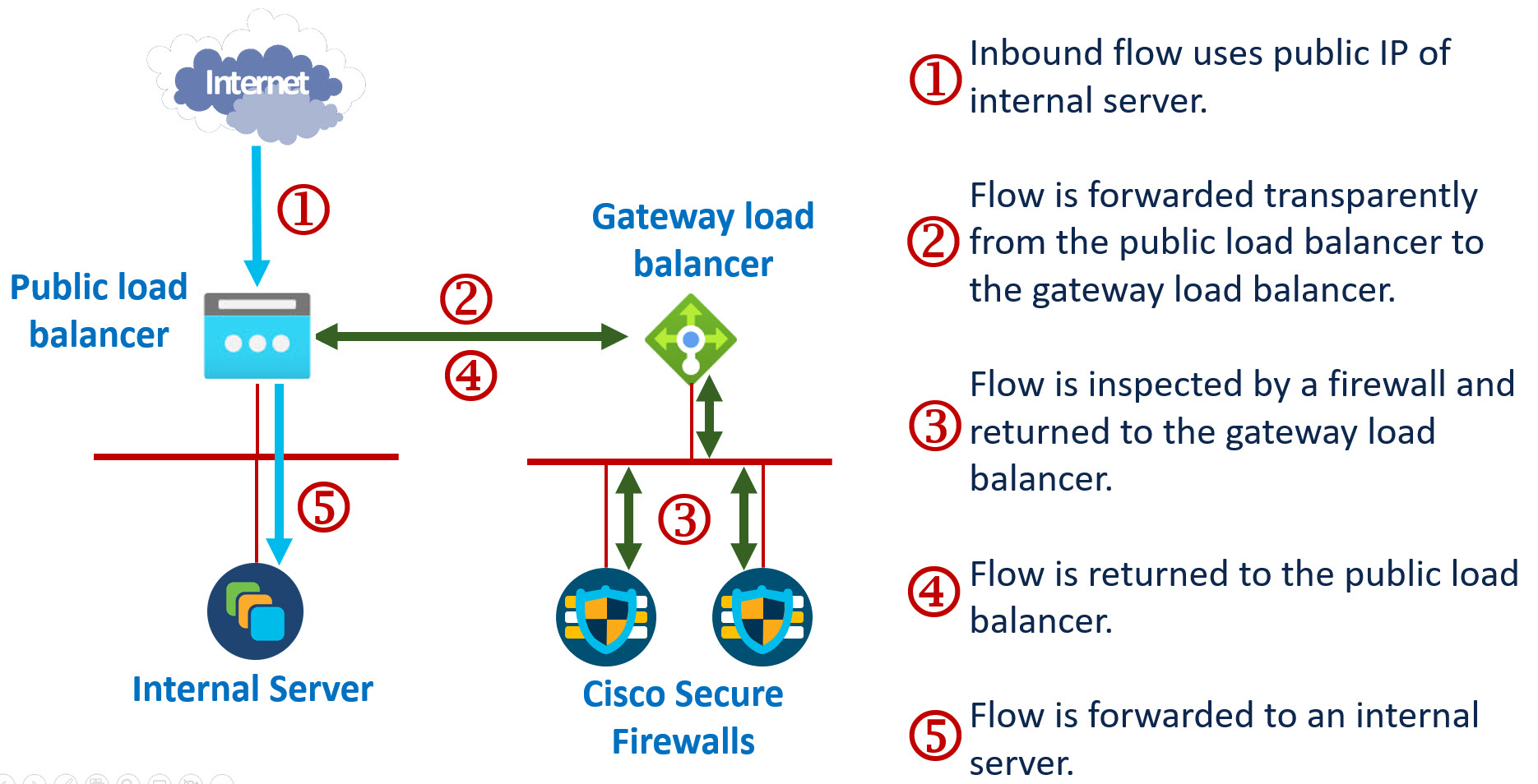
Figure 1. Azure GWLB with network interface associated with a public IP address
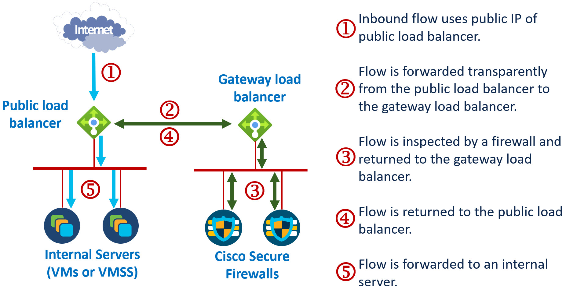
Figure 2. Azure GWLB with network interface associated with a PLB
Notes
The GWLB does not have to be in the same VNet as the VM or PLB. If it is in a separate VNet, the two VNets do not have to be peered. A single GWLB can intercept traffic from multiple VMs and PLBs.
Generally, you want to deploy the GWLB with more than one inspection device to provide resilience. But this is not a requirement. For testing, you may prefer to deploy a single device behind a GWLB.
Configuring the Azure GWLB
Only a high level Azure GWLB configuration presentation is provided. A good reference for a detailed discussion is Tutorial: Create a gateway load balancer using the Azure portal.
This article focuses on using the Azure portal. You could instead use the Azure CLI or PowerShell to create and configure the GWLB.
Creating the GWLB
- Create the GWLB from the same portal page used to create the network load balancers. Note that once you select the GWLB SKU, the type and tier auto-select.
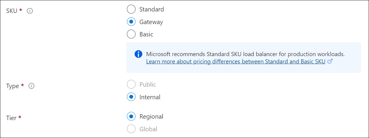
Figure 3. Create a GWLB
-
- Use the Cisco Secure Firewall's VTEP interfaces subnet. These are usually the outside interfaces of the firewalls.
- Choose a static IP address and note the value you select. This will be the (outer) source address of the packets forwarded by the GWLB. You will need this IP address to configure the firewalls.
- Add a backend pool containing the firewalls.
- It is best to leave the UDP ports (10800 and 10801) and segment IDs (800 and 801) set to the default values.
- You can easily add or remove firewalls from the backend pool after you create the GWLB.
- Add the frontend IP configuration.
- Note that the portal grays out the HA checkbox. This means that all forwarded traffic will match this rule.
- Create a health probe from this page. Select TCP protocol and port 443.
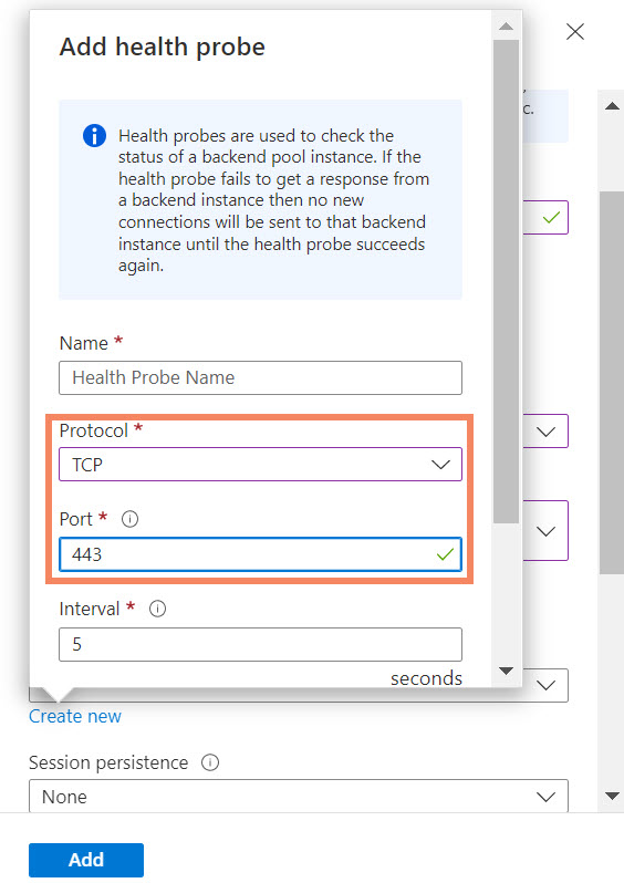
Figure 4. Health probe configuration
- You can skip the outbound rules and tags page.
- Review and create the GWLB.
Associating the GWLB with a VM Network Interface
In the portal, navigate to the VM. Select Networking and select the correct network interface object. Select IP configuration. You can then select the frontend IP configuration of the GWLB from the drop-down list.
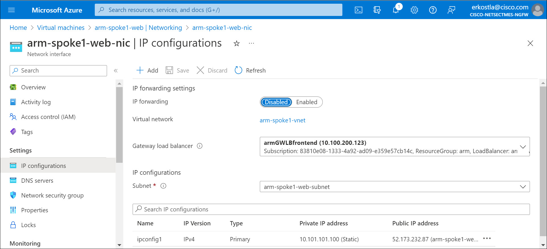
Figure 5. Associate a GWLB to a VM
If the network interface IP configuration does not allow configuration of this attribute, you may have a basic SKU public IP or no public IP address associated with the network interface. The GWLB integration requires the presence of a standard SKU IP address.
Associating the GWLB with a public load balancer (PLB)
In the portal, navigate the PLB. Select the frontend IP configuration of the PLB. Then select the frontend IP configuration of the GWLB from the drop-down list.
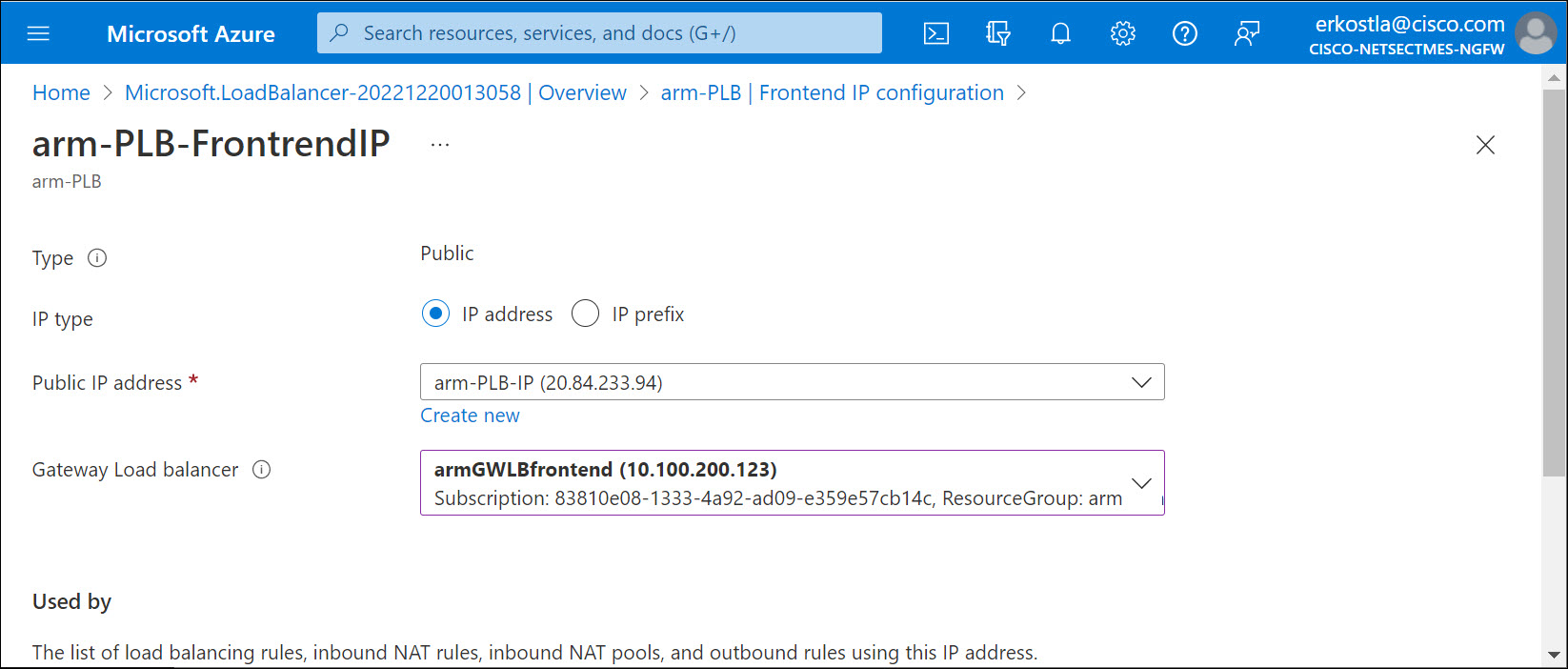
Figure 6. Associate a GWLB to a PLB
If the PLB frontend IP does not allow configuration of this attribute, you may have a basic SKU PLB instead of a standard SKU PLB. You cannot integrate the GWLB with a basic SKU PLB.
Integrating the Cisco Secure Firewall with the GWLB
NVE and VTEP Configuration
- Edit each firewall from the FMC Device Management page. Select the VTEP tab.
- Check the Enable NVE checkbox and click Add VTEP.
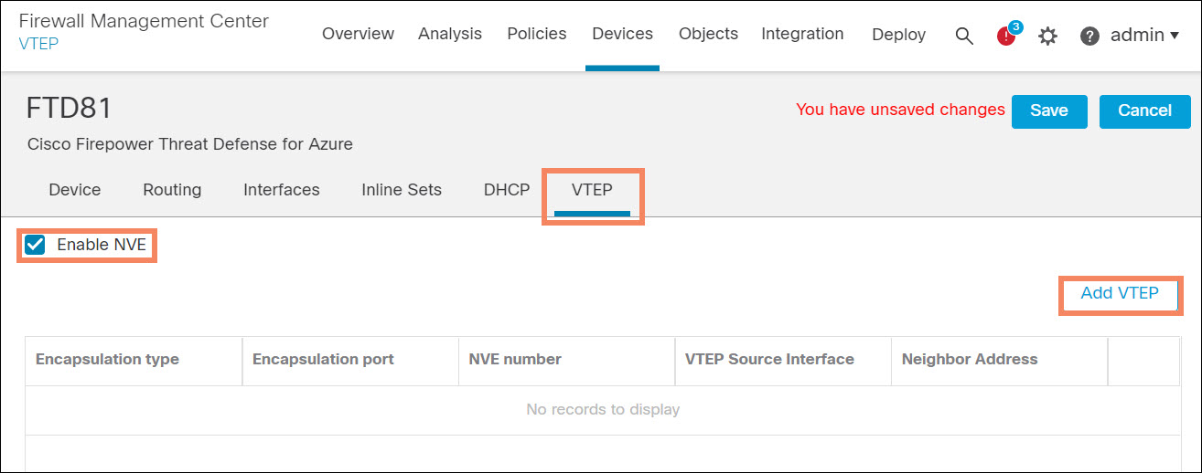
Figure 7. Enable NVE and add VTEP
- Select the VTEP Source Interface. This will usually be the outside interface of the firewall.
- Select Peer VTEP and enter the IP address of the GWLB frontend IP configuration. Click OK,
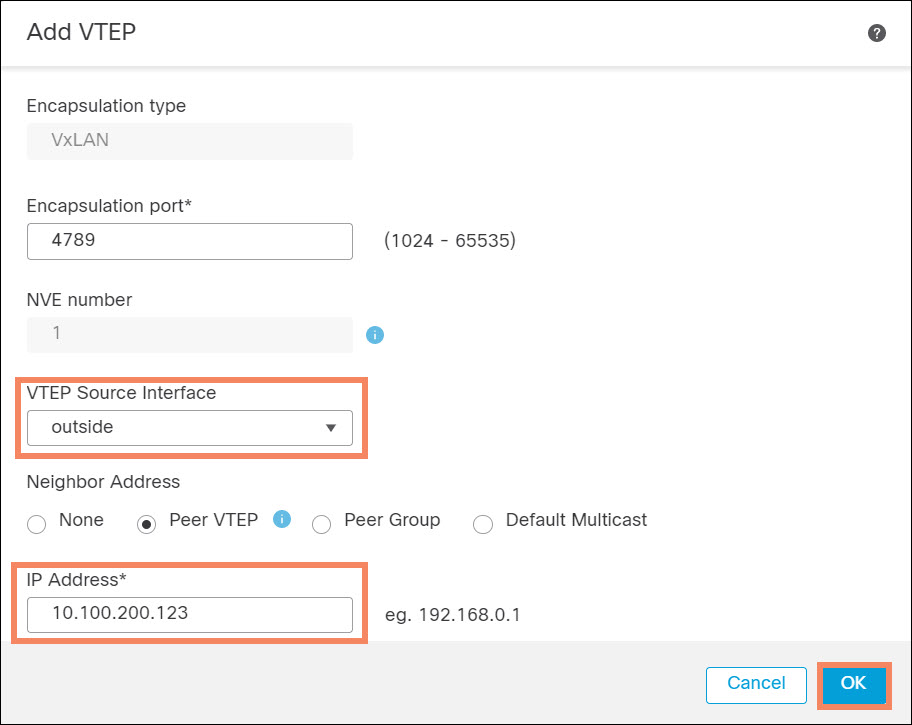
Figure 8. Configure VTEP
VNI Configuration
- Edit each firewall from the FMC Device Management page. Select the Interfaces tab.
- Add a VNI interface.
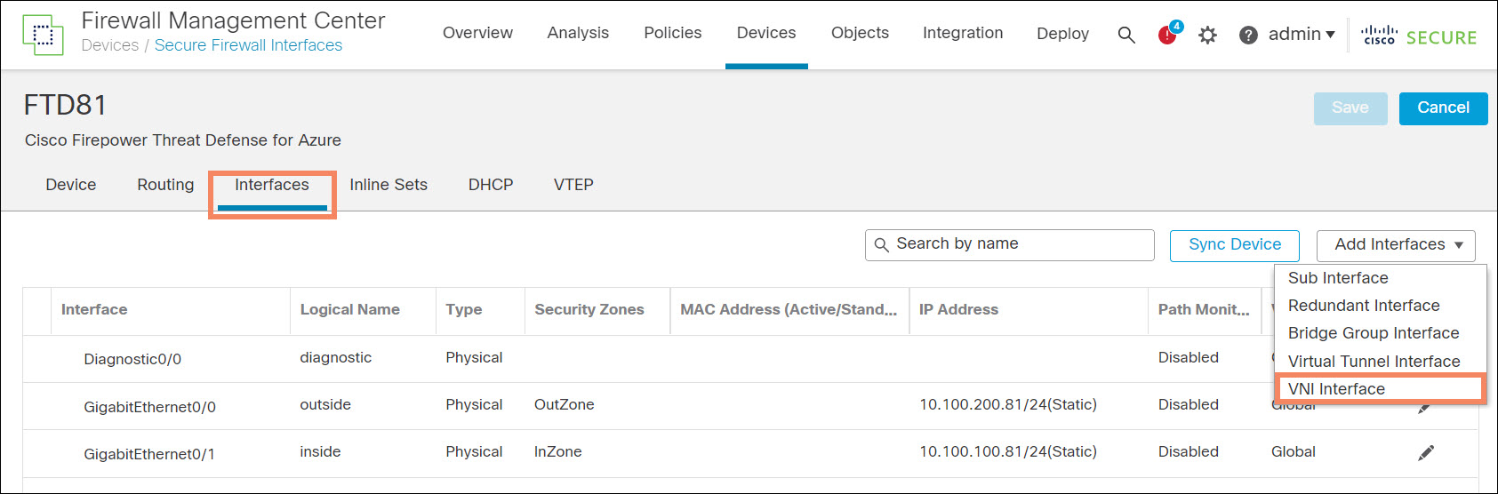
Figure 9. Add VNI
- Enter a name and enable the interface.
- Note that Proxy Paired is enabled.
- Enter UDP ports and segment IDs to match the GWLB settings. The figure below uses the GWLB default settings.
- Check the NVE Mapped to VTEP Interface checkbox. Click OK.
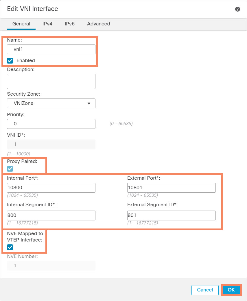
Figure 10. Configure VNI
Note that you do not have to configure an IP address on the VNI.
Platform Settings
Platform settings enable the firewalls to respond to the health probe from the GWLB.
- Navigate to Devices > Platform Settings and create platform settings for the firewalls if one does not exist.
- Under HTTP Access enable the HTTP server,
- Add the security zone of the VTEP and add a network object that includes the IP address 168.63.129.16. This is the source IP of the health probe.
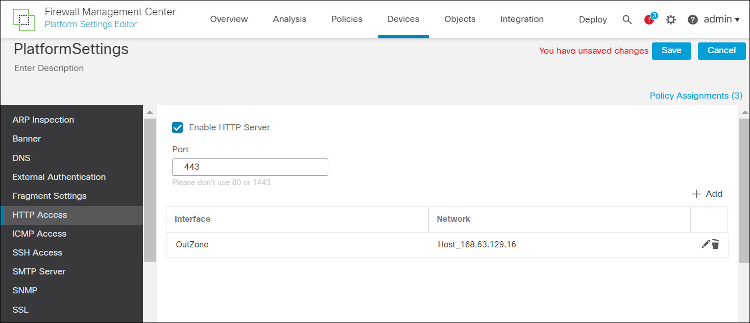
Figure 11. Platform settings
Routing Configuration
You do not have to configure a route to respond to traffic forwarded by the GWLB. The VNI proxy configuration on the Cisco Secure Firewall will hair-pinned all traffic received on the VNI.
However, the GWLB health probe has a source address of 168.63.129.16. You must configure a static route to this address through the VTEP interface. Usually, the default route on the outside interface fulfills this requirement.
NAT Configuration
You must not NAT any of the traffic forwarded by the GWLB.
Access Control Policy
All traffic forwarded by the GWLB has both the source and destination in the VNI security zone. Therefore, you cannot create rules to allow or block traffic based on security zone, unless you want to treat all forwarded traffic the same. In the place of security zones, you can, for example use source and destination IP addresses.
Troubleshooting
Health Probe Status
You can check the health status of the firewalls. In the Azure portal, navigate to the GWLB and select Metrics > Metric > Health Probe > Status.
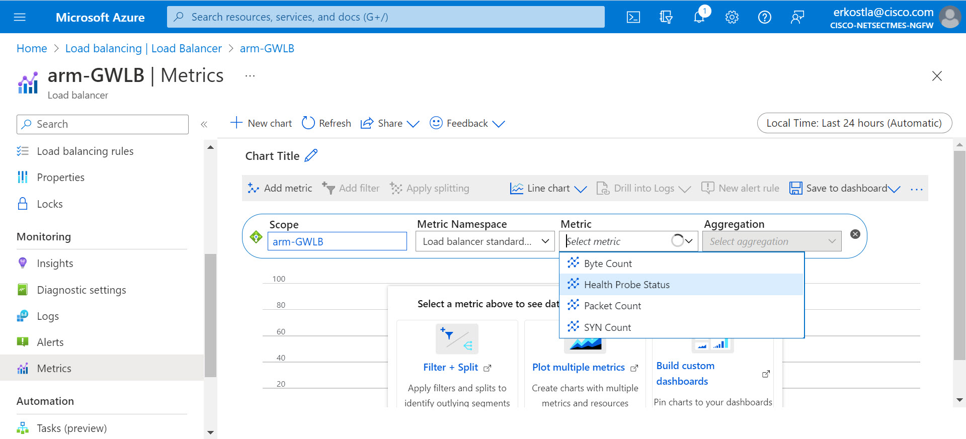
Figure 12. Health probe status
You may wish to reduce the time scale of the graph from the default 24 hours. Apply splitting by backend IP address to see the traffic of each firewall's health individually.
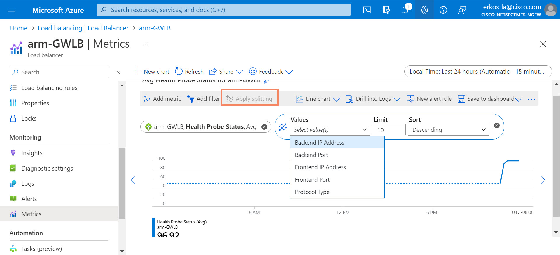
Figure 13. Apply splitting
If you cannot find a configuration issue (Azure or firewall) responsible for the health probe failure, you may wish to capture traffic on the VTEP to help analyze the issue. See the following section.
Traffic Capture on the VTEP
If the firewall is not able to inspect traffic, it is useful to capture traffic on the VTEP, which is typically the outside interface of the firewall.
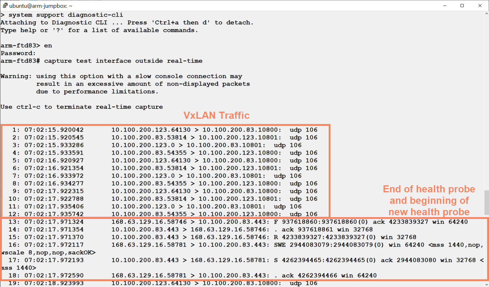
Figure 14. Traffic capture on the VTEP
Note
There are several methods to capture traffic. Figure 14 and Figure 15 show the real-time packet captures on the data plane, which is convenient if you do not have much traffic. For example, while testing a deployment. To run a real-time packet capture, you must log into the firewall and access the diagnostic CLI.
To access the diagnostic CLI from the Cisco Secure Firewall CLI, enter system support diagnostic-cli. Then enter enabled mode by typing enable, or simply en. When prompted for a password, hit .
- If you do not see any traffic at all, check the GWLB configuration, the inbound effective security rules on the VTEP network interface object, and the interface configuration on the firewall.
- If you see the SYN packet coming from the health probe (168.63.129.16) but no response, check your platform settings.
- If you see successful health probe communication, but no UDP traffic, check the inbound effective security rules on the VTEP network interface object, and confirm that you associated the GWLB with the target VM or PLB.
Packet Capture on the VNI
You can capture traffic on the VNI to see the flows forwarded to the firewall.
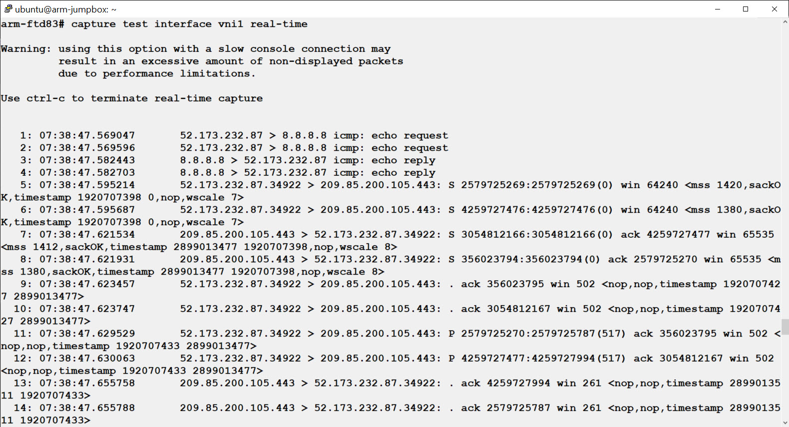
Figure 15. Traffic capture on the VNI
Here we see a single ping followed by an HTTPS request. Note that we see each packet twice as it passes through the firewall.
- If you do not see any traffic on the VNI, confirm that you associated the GWLB with the target VM or PLB.
- If you see a packet only once, the firewall is dropping the packet. If you do not expect this, check your policy. Running clear asp drop followed by show asp drop can give you a hint as to why the firewall is dropping packets.
Inspect the NVE
The show nve command provides useful information.
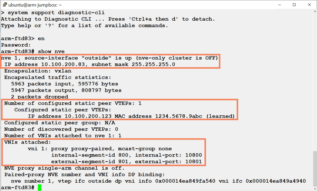
Figure 16, The show nve command
- Confirm that you configured the correct interface as the VTEP (in this case outside) and that the interface is up.
- Confirm that the peer VTEP IP address is the address of the GWLB. If the firewall does not learn the MAC address of the peer VTEP, there is a configuration or communication issue.
- Confirm that the VNI internal and external segment IDs and UDP ports match the values of the GWLB backend pool.
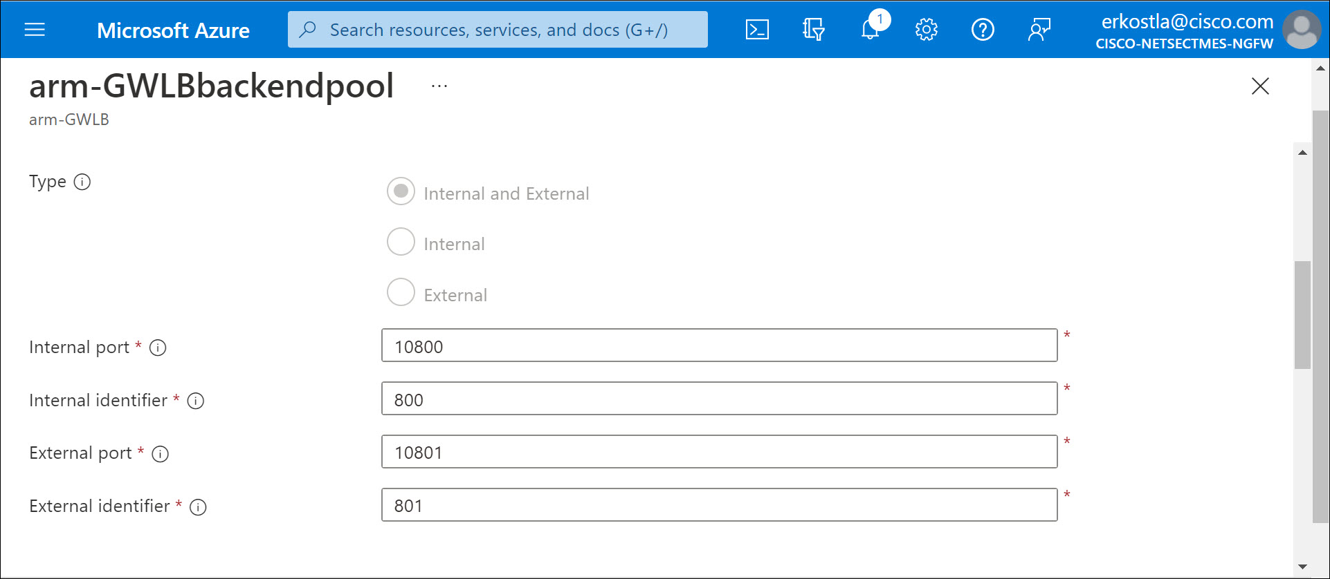
Figure 17. GWLB segment IDs and UDP ports
Including East-West Traffic Inspection
The following sample topology allows for north-south, outbound, and east-west traffic inspection with a single set of firewalls. For east-west traffic the topology includes an Azure ILB.
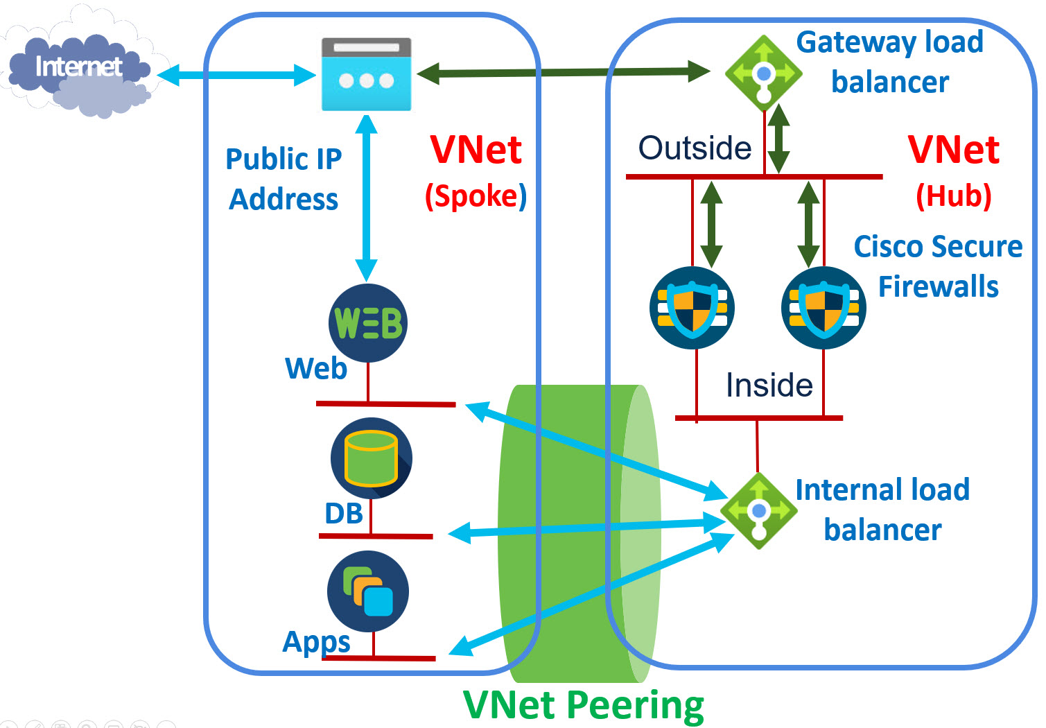
Figure 18. Sample topology
Note
There is a trick needed to include both a GWLB and ILB in the same The GWLB is a type of ILB, and you cannot use two NIC objects from the same VMs to two ILB backend pools. Therefore, when configuring the backend pool for at least one of the load balancers, use IP addresses instead of NIC objects.
📚Additional Resources
- This document provides more information about VXLAN implementation on the Cisco Secure Firewall: VXLAN and GENEVE Support.
- For general information about deploying the Cisco Secure Firewall in Azure, see Chapter: Deploy the Threat Defense Virtual on Azure.
- For a detailed step-by-step instructions to configure an Azure GWLB, see Tutorial: Create a gateway load balancer using the Azure portal.
- For Cisco Secure Firewall cluster integration with the Azure GWLB, see Virtual Firewall Clustering.
- For Cisco Secure Firewall autoscale integration with the Azure GWLB, see Auto Scale with Azure Gateway Load Balancer Use Case.
- There is also the Azure gateway load balancer companion video on YouTube,. Cisco Secure Firewall 7.3 Release - Azure Gateway Load Balancer.
Updated about 2 years ago