Dynamic Virtual Tunnel Interface (DVTI)
Introduction
Release 7.3 introduces support for Dynamic Virtual Tunnel Interface on Firewall Threat Defense (FTD).
Background Information
Release 6.7 introduced Static VTI (SVTI) support for building route-based VPNs, which helps simplify configuration by not needing to manage complex access lists and correctly ordering the crypto maps. However, SVTIs have some limitations:
- For large enterprise hub and spoke deployments managing the VTI configuration for hundreds of SVTIs is challenging and time-consuming.
- Adding a new spoke requires a new SVTI on the Hub.
- For spokes using DHCP on the outside interface, the Hub needs a configuration update every time the spoke's IP address changes.
DVTI overcomes these limitations by:
- Using only one DVTI for hundreds of spokes, instead of configuring one SVTI per spoke.
- Requiring no additional VPN configuration when adding new spokes on the Hub (NAT and routing configuration updates may be needed depending upon the setup).
- Requiring no configuration update on the Hub when the spoke's DHCP IP address changes.
Note
More than one DVTI may be needed depending upon the setup. For example, if you have dual ISP connections, or if you have both IPv4 and IPv6 traffic.
About Dynamic Virtual Tunnel Interface
DVTI provides support for dynamic instantiation and VPN tunnel management. DVTI uses the IP unnumbered interface functionality to borrow the IP address from another interface which also helps conserve IP addresses. DVTI supports EIGRP, OSPF and BGP routing protocols for dynamic route installation.
How does DVTI Work?
The virtual template is attached to a tunnel group. When the VPN tunnel is established successfully, the DVTI configuration is cloned, and a new Virtual Access (VA) Interface is created for that spoke. Since the virtual template configuration is cloned automatically, we don't have to create a separate SVTI for every spoke. Cloning the configuration also helps preserve IP addresses, as all virtual access interfaces use the same IP address. Traffic that hits this virtual access interface is then encrypted and sent to the spoke. The virtual access interface remains active until the VPN session is terminated.
Security Zones can be applied to DVTI to use in policies like Access Control and NAT.
Note
The same virtual template can be attached to multiple tunnel-groups.
VPN sessions using DVTIs only support IKEv2.
Configuration
This section covers the configuration for single hub and dual hub configurations.
Single Hub
Topology

Adding a loopback interface (on Hub and all spokes)
Check the Loopback Interfaces document for detailed steps to configure a loopback interface.
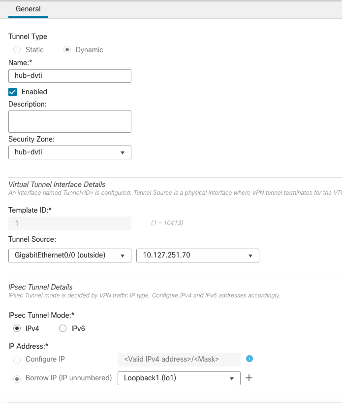
Adding a Dynamic Virtual Tunnel Interface (on the Hub only)
Step 1: Navigate to Devices > Device Management and Edit the settings for the hub
Step 2: Click on Add Interfaces > Virtual Tunnel Interface

Step 3: In the pop-up window select/enter the following:
-
Tunnel Type: Dynamic
-
Name: The name for the interface used to refer to this interface
-
Enabled: Select the checkbox (selected by default)
-
Description: A brief description of the tunnel interface (optional)
-
Security Zone: Configure the Security zone for this interface
-
Template ID: Enter a unique ID for the interface. A number between 1-10413.
-
Tunnel Source: The interface used to source the VPN tunnels. Spokes initiate the VPN tunnel to this interface's IP address. Once you select the tunnel source interface, select the interface's IP address in the next box.
-
Tunnel Mode: Select whether this tunnel uses for IPv4 or IPv6 traffic.
-
IP Address: For DVTI, we can only borrow the IP address from another interface. Select the Loopback interface created above.
Adding a Static Virtual Tunnel Interface (on all the spokes)
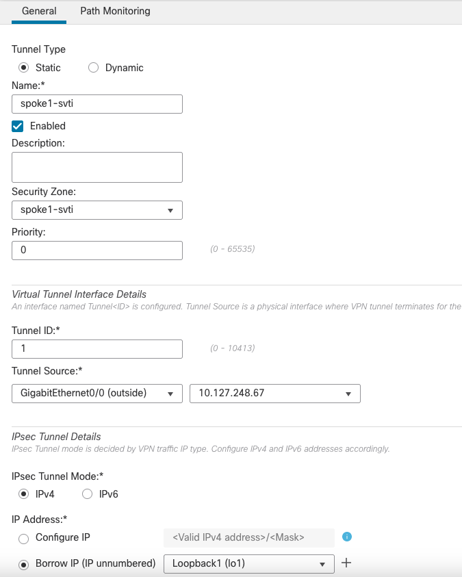
To add a Static VTI, follow the same steps for adding a Dynamic VTI, but instead of selecting the tunnel type as 'Dynamic', select the tunnel type as 'Static'. The rest of the settings are the same.
Configuring the VPN topology
To configure a new VPN topology, go to Devices > VPN > Site To Site > + Site to Site VPN
Enter the following details in the pop-up:
- Topology Name: The name for the VPN topology
- Select the Route Based (VTI) Radio Button
- In the Network Topology select Hub and Spoke
- Click on the + sign next to Hub Nodes to add a new hub
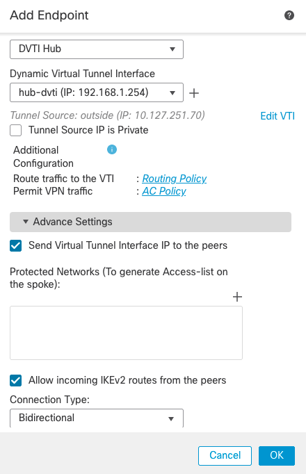
- Enter the following details in the pop-up window
- Device: Select the Hub FTD
- Dynamic Virtual Tunnel Interface: Select the virtual template interface for this VPN topology
- Under the Advanced settings:
- Allow incoming IKEv2 routes from the peers: Check this box if you want the Hub to accept routes from the spokes and install them in the routing table.
- Select the check box for Send Virtual Tunnel Interface IP to the peers
- Enter the following details in the pop-up window
Warning
This setting allows the device to send the tunnel interface IP address to the peers, so that the peers can add a /32 route for this IP address through their tunnel interface. This /32 route is needed for reachability to the peer's tunnel interface IP addresses if you are using static routes or BGP (which sends unicast messages to the neighbour IP address). Without this route the spokes cannot reach the hubs virtual tunnel interface IP through their tunnel interface, and may end up routing the packets through another interface.
This setting is not needed for EIGRP or OSPF as they use multicast for peering.
- Click on the + sign next to Spoke Nodes to add a new spoke
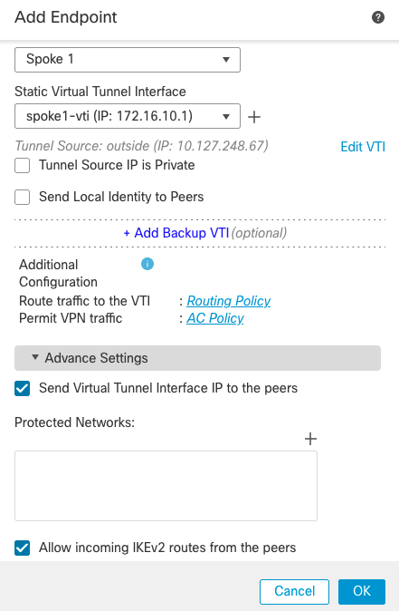
- Enter the following details in the pop-up window
- Device: Select the Spoke FTD
- Static Virtual Tunnel Interface: Select the virtual template interface for this VPN topology
- Leave the other settings as default
- Enter the following details in the pop-up window
Note
Send Virtual Tunnel Interface IP to the peers is enabled by default for spoke devices.
- Add additional spokes as needed
- Configure the IKE and IPSec parameters as needed or leave them as default
- The final topology should look like this:
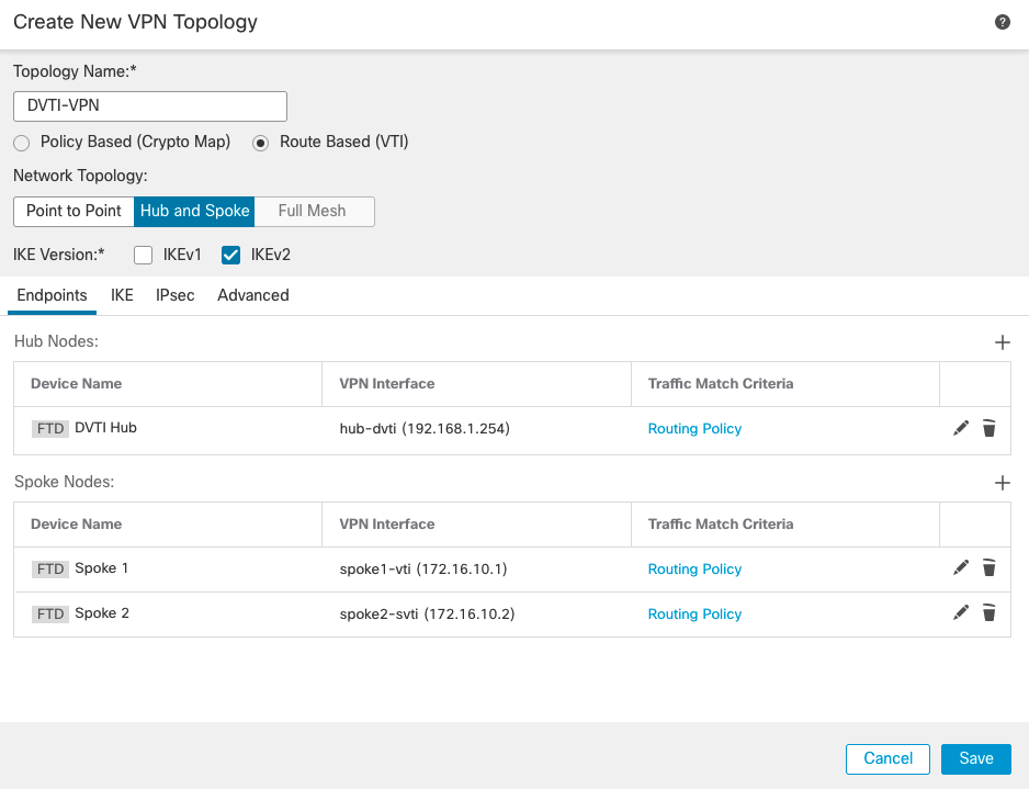
- Click on Save to save the topology
Routing Protocol Configuration
This example uses BGP as the routing protocol.
- To configure BGP, go to Devices > Device Management > Hub FTD > Routing
- On the left pane, go to General Settings > BGP
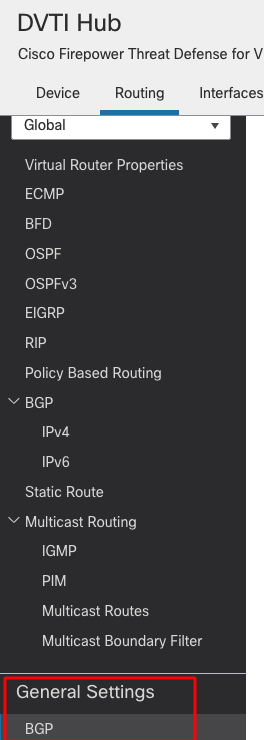
- On the right pane, check the box next to Enable BGP and enter the AS number
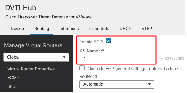
- Other fields are optional and can be filled as per requirements.
- Click on Save to save the change.
- On the left pane, go to BGP > IPv4
- On the right pane, check the box Enable IPv4
- Then go to the Neighbor tab and click on Add
- Enter the following details in the pop-up window
- IP Address: Peer's IP address. In this case, Spoke 1's tunnel interface IP address
- Remote AS: Peer's AS number
- Check the box Enabled Address
- Other fields are optional and can be configured per requirements or left as default
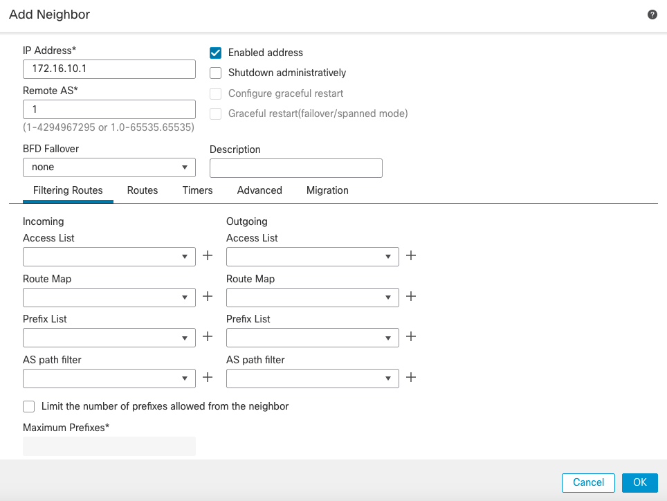
- Add another neighbour for Spoke 2

- Click on Save to save the changes.
- Go to the Networks tab and click on Add to advertise the networks to the peers.
- Select the network objects behind the Hub to advertise

- BGP configuration is similar on the spokes with the following differences:
- The neighbour uses the Hub's tunnel interface IP address
- The networks will be the respective networks behind that spoke
- Save the configuration and deploy the policies to all the devices
Dual Hub
Most of the Dual Hub configuration is the same as the Single Hub setup. Below highlights only the differences.
Note
Spokes require two loopback and two virtual tunnel interfaces, one per hub. The configuration of the interfaces remains the same as in the single hub scenario.
Topology

Configuring the VPN Topology
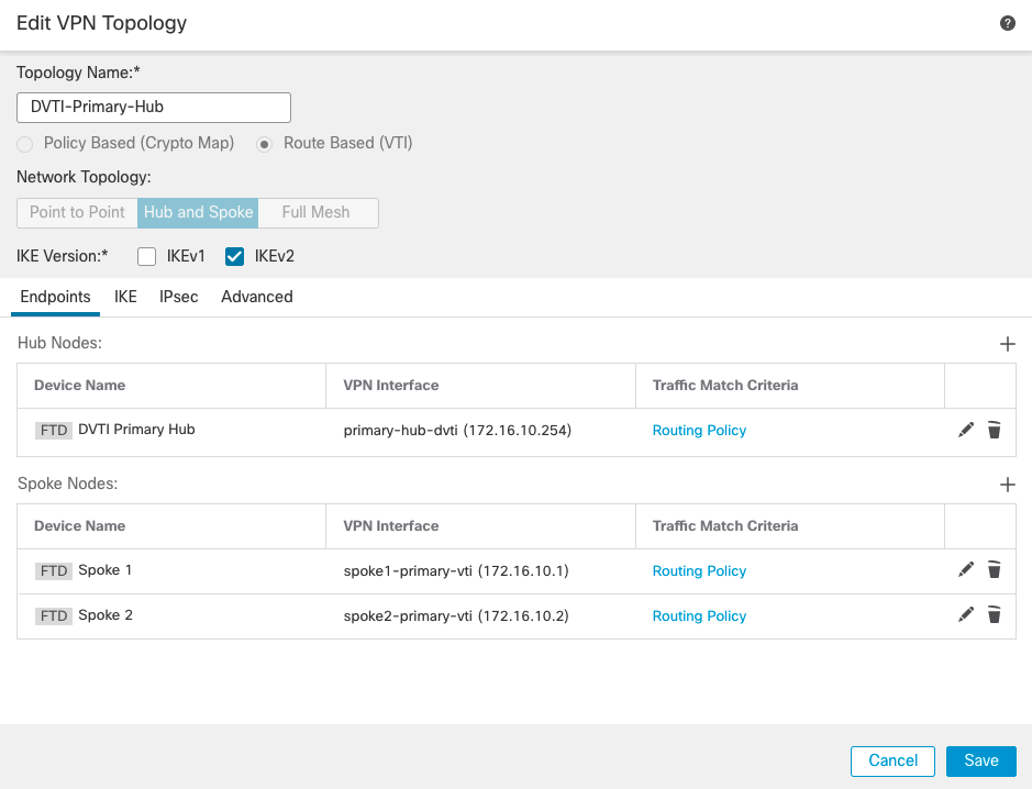
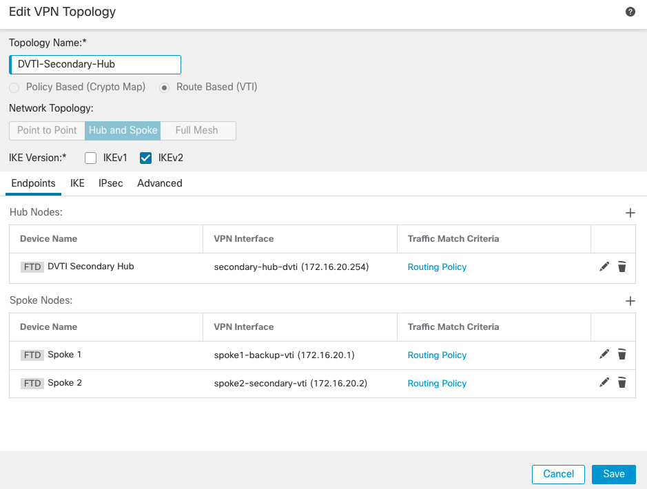
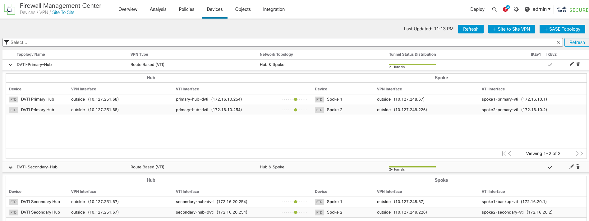
The configuration steps for the VPN topologies is the same, except that it requires two VPN topologies, one per Hub.
Primary Hub
Secondary Hub
The final topologies.
Configuring the Routing Protocol
- BGP configuration is the same, except that we need to add both hubs as neighbours on the spokes.

Verification and Troubleshooting
Show commands
Single Hub
The show run interface virtual template command shows the details of the virtual template interface.
hub# sh run interface virtual-Template 1
  interface Virtual-Template1 type tunnel
  nameif hub-dvti
  ip unnumbered lo1
  tunnel source interface outside
  tunnel mode ipsec ipv4
  tunnel protection ipsec profile FMC_IPSEC_PROFILE_1
The show ip command shows the Virtual Access interfaces (one per active VPN tunnel). Notice that all the virtual access interfaces have the same IP address.
hub# sh ip
  System IP Addresses:
  Interface                Name                   IP address      Subnet mask     Method
  GigabitEthernet0/0       outside                10.127.251.70   255.255.255.224 manual
  GigabitEthernet0/1       inside                 10.254.254.1    255.255.255.0   manual
  Loopback1                lo1                    172.16.10.254   255.255.255.0   manual
  Virtual-Access1          hub-dvti_va13          172.16.10.254   255.255.255.0   CONFIG
  Virtual-Access2          hub-dvti_va14          172.16.10.254   255.255.255.0   CONFIG
  Virtual-Template1        hub-dvti               172.16.10.254   255.255.255.0   CONFIG
The show crypto ikev2 sa command shows details of the IKE session.
hub# sh crypto ikev2 sa
  IKEv2 SAs:

  Session-id:13, Status:UP-ACTIVE, IKE count:1, CHILD count:1

  Tunnel-id Local                                               Remote                                     fvrf/ivrf     Status         Role
  35929679 10.127.251.70/500                                   10.127.248.67/500                             /Global      READY    RESPONDER
  Encr: DES, Hash: SHA96, DH Grp:14, Auth sign: PSK, Auth verify: PSK
  Life/Active Time: 86400/1219 sec
  Child sa: local selector  0.0.0.0/0 - 255.255.255.255/65535
  remote selector 0.0.0.0/0 - 255.255.255.255/65535
  ESP spi in/out: 0x4d0b3c69/0x2210cce6

  IKEv2 SAs:

  Session-id:14, Status:UP-ACTIVE, IKE count:1, CHILD count:1

  Tunnel-id Local                                               Remote                                     fvrf/ivrf     Status         Role
  38062557 10.127.251.70/500                                   10.127.249.226/500                            /Global      READY    RESPONDER
  Encr: DES, Hash: SHA96, DH Grp:14, Auth sign: PSK, Auth verify: PSK
  Life/Active Time: 86400/1219 sec
  Child sa: local selector  0.0.0.0/0 - 255.255.255.255/65535
  remote selector 0.0.0.0/0 - 255.255.255.255/65535
  ESP spi in/out: 0x4f94e390/0x1c5bc4ba
The show crypto ipsec sa command shows the details of the IPSec session.
hub# show crypto ipsec sa
  interface: hub-dvti_va13
  Crypto map tag: hub-dvti_vtemplate_dyn_map, seq num: 1, local addr: 10.127.251.70

  Protected vrf (ivrf): Global
  local ident (addr/mask/prot/port): (0.0.0.0/0.0.0.0/0/0)
  remote ident (addr/mask/prot/port): (0.0.0.0/0.0.0.0/0/0)
  current_peer: 10.127.248.67


  #pkts encaps: 466, #pkts encrypt: 466, #pkts digest: 466
  #pkts decaps: 466, #pkts decrypt: 466, #pkts verify: 466
  #pkts compressed: 0, #pkts decompressed: 0
  #pkts not compressed: 466, #pkts comp failed: 0, #pkts decomp failed: 0
  #pre-frag successes: 0, #pre-frag failures: 0, #fragments created: 0
  #PMTUs sent: 0, #PMTUs rcvd: 0, #decapsulated frgs needing reassembly: 0
  #TFC rcvd: 0, #TFC sent: 0
  #Valid ICMP Errors rcvd: 0, #Invalid ICMP Errors rcvd: 0
  #send errors: 0, #recv errors: 0

  local crypto endpt.: 10.127.251.70/500, remote crypto endpt.: 10.127.248.67/500
  path mtu 1500, ipsec overhead 58(36), media mtu 1500
  PMTU time remaining (sec): 0, DF policy: copy-df
  ICMP error validation: disabled, TFC packets: disabled
  current outbound spi: 2210CCE6
  current inbound spi : 4D0B3C69

  inbound esp sas:
  spi: 0x4D0B3C69 (1292581993)
  SA State: active
  transform: esp-des esp-sha-hmac no compression
  in use settings ={L2L, Tunnel, IKEv2, VTI, }
  slot: 0, conn_id: 13, crypto-map: hub-dvti_vtemplate_dyn_map
  sa timing: remaining key lifetime (kB/sec): (4147169/27489)
  IV size: 8 bytes
  replay detection support: Y
  Anti replay bitmap:
  0xFFFFFFFF 0xFFFFFFFF
  outbound esp sas:
  spi: 0x2210CCE6 (571526374)
  SA State: active
  transform: esp-des esp-sha-hmac no compression
  in use settings ={L2L, Tunnel, IKEv2, VTI, }
  slot: 0, conn_id: 13, crypto-map: hub-dvti_vtemplate_dyn_map
  sa timing: remaining key lifetime (kB/sec): (4285409/27489)
  IV size: 8 bytes
  replay detection support: Y
  Anti replay bitmap:
  0x00000000 0x00000001

  interface: hub-dvti_va14
  Crypto map tag: hub-dvti_vtemplate_dyn_map, seq num: 1, local addr: 10.127.251.70

  Protected vrf (ivrf): Global
  local ident (addr/mask/prot/port): (0.0.0.0/0.0.0.0/0/0)
  remote ident (addr/mask/prot/port): (0.0.0.0/0.0.0.0/0/0)
  current_peer: 10.127.249.226


  #pkts encaps: 80, #pkts encrypt: 80, #pkts digest: 80
  #pkts decaps: 81, #pkts decrypt: 81, #pkts verify: 81
  #pkts compressed: 0, #pkts decompressed: 0
  #pkts not compressed: 80, #pkts comp failed: 0, #pkts decomp failed: 0
  #pre-frag successes: 0, #pre-frag failures: 0, #fragments created: 0
  #PMTUs sent: 0, #PMTUs rcvd: 0, #decapsulated frgs needing reassembly: 0
  #TFC rcvd: 0, #TFC sent: 0
  #Valid ICMP Errors rcvd: 0, #Invalid ICMP Errors rcvd: 0
  #send errors: 0, #recv errors: 0

  local crypto endpt.: 10.127.251.70/500, remote crypto endpt.: 10.127.249.226/500
  path mtu 1500, ipsec overhead 58(36), media mtu 1500
  PMTU time remaining (sec): 0, DF policy: copy-df
  ICMP error validation: disabled, TFC packets: disabled
  current outbound spi: 1C5BC4BA
  current inbound spi : 4F94E390

  inbound esp sas:
  spi: 0x4F94E390 (1335157648)
  SA State: active
  transform: esp-des esp-sha-hmac no compression
  in use settings ={L2L, Tunnel, IKEv2, VTI, }
  slot: 0, conn_id: 14, crypto-map: hub-dvti_vtemplate_dyn_map
  sa timing: remaining key lifetime (kB/sec): (4285435/27489)
  IV size: 8 bytes
  replay detection support: Y
  Anti replay bitmap:
  0xFFFFFFFF 0xFFFFFFFF
  outbound esp sas:
  spi: 0x1C5BC4BA (475776186)
  SA State: active
  transform: esp-des esp-sha-hmac no compression
  in use settings ={L2L, Tunnel, IKEv2, VTI, }
  slot: 0, conn_id: 14, crypto-map: hub-dvti_vtemplate_dyn_map
  sa timing: remaining key lifetime (kB/sec): (4147195/27489)
  IV size: 8 bytes
  replay detection support: Y
  Anti replay bitmap:
  0x00000000 0x00000001
Note
The interface name is different for each spoke, and corresponds to a different virtual access interface that was dynamically created at the time of the tunnel establishment.
The local and remote selectors are 0.0.0.0, so all traffic hitting the interface is encrypted and sent across the tunnel.
The show route command shows the details of the Peer IP address and BGP routes exchanged.
hub# sh route
  Codes: L - local, C - connected, S - static, R - RIP, M - mobile, B - BGP
  D - EIGRP, EX - EIGRP external, O - OSPF, IA - OSPF inter area
  N1 - OSPF NSSA external type 1, N2 - OSPF NSSA external type 2
  E1 - OSPF external type 1, E2 - OSPF external type 2, V - VPN
  i - IS-IS, su - IS-IS summary, L1 - IS-IS level-1, L2 - IS-IS level-2
  ia - IS-IS inter area, * - candidate default, U - per-user static route
  o - ODR, P - periodic downloaded static route, + - replicated route
  SI - Static InterVRF, BI - BGP InterVRF
  Gateway of last resort is 10.127.251.65 to network 0.0.0.0

  S*       0.0.0.0 0.0.0.0 [1/0] via 10.127.251.65, outside
  B        10.1.1.0 255.255.255.0 [200/0] via 172.16.10.1, 00:12:46
  B        10.2.2.0 255.255.255.0 [200/0] via 172.16.10.2, 00:12:46
  C        10.127.251.64 255.255.255.224 is directly connected, outside
  L        10.127.251.70 255.255.255.255 is directly connected, outside
  C        10.254.254.0 255.255.255.0 is directly connected, inside
  L        10.254.254.1 255.255.255.255 is directly connected, inside
  C        172.16.10.0 255.255.255.0 is directly connected, lo1
  V        172.16.10.1 255.255.255.255
  connected by VPN (advertised), hub-dvti_va13
  V        172.16.10.2 255.255.255.255
  connected by VPN (advertised), hub-dvti_va14
  L        172.16.10.254 255.255.255.255 is directly connected, lo1
Note
There are two /32 routes for the spokes' tunnel interface IP address, because we enabled the "Send Virtual Tunnel Interface IP to the peers" setting on all the devices.
Dual Hub
The show commands for VPN sessions and routing protocols are the same.
Depending upon the routing configuration on the spokes, you will see the network behind the hubs being learnt through both the primary Hub and the secondary Hub and prefer a particular hub.
The show bgp command shows the spoke is learning the network behind the hubs through both hubs.
spoke1# sh bgp
  BGP table version is 6, local router ID is 172.16.10.2
  Status codes: s suppressed, d damped, h history, * valid, > best, i - internal,
    r RIB-failure, S Stale, m multipath
    Origin codes: i - IGP, e - EGP, ? - incomplete

  Network          Next Hop        Metric LocPrf Weight  Path
    *> 10.2.2.0/24      0.0.0.0              0         32768  i
    r>i10.254.254.0/24  172.16.20.254        0    100      0  i
    r i                 172.16.10.254        0    100      0  I
The show route command shows that the spoke prefers the path through the primary Hub and uses it to route the traffic.
spoke1# sh route
  Codes: L - local, C - connected, S - static, R - RIP, M - mobile, B - BGP
  D - EIGRP, EX - EIGRP external, O - OSPF, IA - OSPF inter area
  N1 - OSPF NSSA external type 1, N2 - OSPF NSSA external type 2
  E1 - OSPF external type 1, E2 - OSPF external type 2, V - VPN
  i - IS-IS, su - IS-IS summary, L1 - IS-IS level-1, L2 - IS-IS level-2
  ia - IS-IS inter area, * - candidate default, U - per-user static route
  o - ODR, P - periodic downloaded static route, + - replicated route
  SI - Static InterVRF, BI - BGP InterVRF
  Gateway of last resort is 10.127.249.225 to network 0.0.0.0

  S*       0.0.0.0 0.0.0.0 [1/0] via 10.127.249.225, outside
  D EX     10.1.1.0 255.255.255.0
  [170/51712] via 172.16.10.254, 01:39:31, spoke2-primary-vti
  C        10.2.2.0 255.255.255.0 is directly connected, inside
  L        10.2.2.1 255.255.255.255 is directly connected, inside
  C        10.127.249.224 255.255.255.224 is directly connected, outside
  L        10.127.249.226 255.255.255.255 is directly connected, outside
  D EX     10.254.254.0 255.255.255.0
  [170/26112] via 172.16.10.254, 01:39:31, spoke2-primary-vti
  C        172.16.10.0 255.255.255.0 is directly connected, lo1
  D        172.16.10.1 255.255.255.255
  [90/51456] via 172.16.10.254, 01:39:31, spoke2-primary-vti
  L        172.16.10.2 255.255.255.255 is directly connected, lo1
  V        172.16.10.254 255.255.255.255
  connected by VPN (advertised), spoke2-primary-vti
  C        172.16.20.0 255.255.255.0 is directly connected, lo2
  L        172.16.20.2 255.255.255.255 is directly connected, lo2
  V        172.16.20.254 255.255.255.255
  connected by VPN (advertised), spoke2-secondary-vti
Limitations
- ECMP and VRFs are not supported with DVTI
- DVTI is not supported in Cluster mode
- A maximum of 1000 DVTIs is supported on a device
Summary
DVTIs greatly reduce the complexity and configuration required for managing a VPN solution with multiple spokes. Previously, the Hub required ~10 lines of configuration per spoke, but DVTI only needs a total of ~15 lines of configuration irrespective of the number of spokes. Also, new spokes can be added seamlessly without having to update the VPN configuration on the Hub.
📚Additional Resources
Updated 3 months ago
