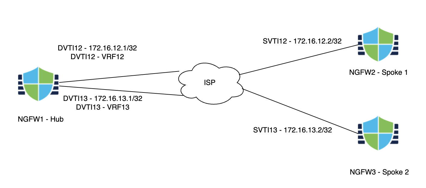
Scenario 5 - VRF Support for DVTI using SD-WAN Wizard
Virtual Route Forwarding (VRF) enables customers to separate out routing and forwarding domains for ease of operations. VRFs were first introduced in version 6.6 and Dynamic Virtual Tunnel Interfaces were introduced in 7.3. In this version, we add the ability to associate a DVTI with a VRF to help with network segmentation. While version 7.6, introduces the ability to configure a SD-WAN Topology straight from a startup wizard.
Lab Tasks
These are the tasks in the scenario below. If you are familiar with the Secure Firewall you may do these on your own, or for step-by-step instructions see below.
- Task 1 - Configure DVTIs on NGFW1
- Task 2 - Configure VRFs on NGFW1
- Task 3 - Configure VPN Topologies
- Task 4 - Verification
Task 1 - Configure DVTIs on NGFW1
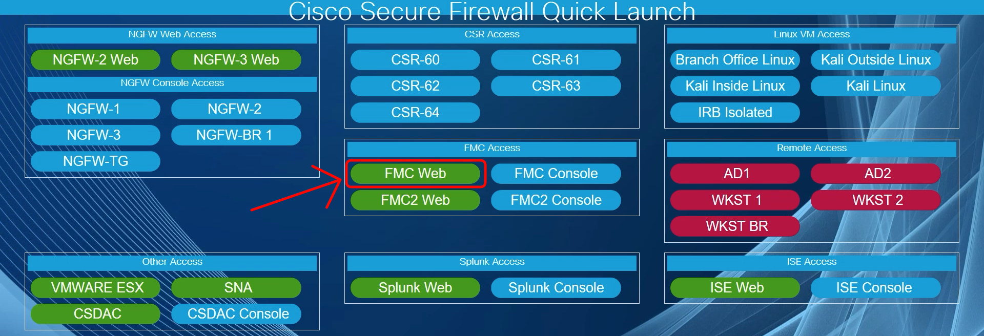
- Using the Quick Launch or the Google Chrome browser connect to the FMC web UI.
Login as admin/C1sco12345. These credentials should be pre-populated in the browser.
-
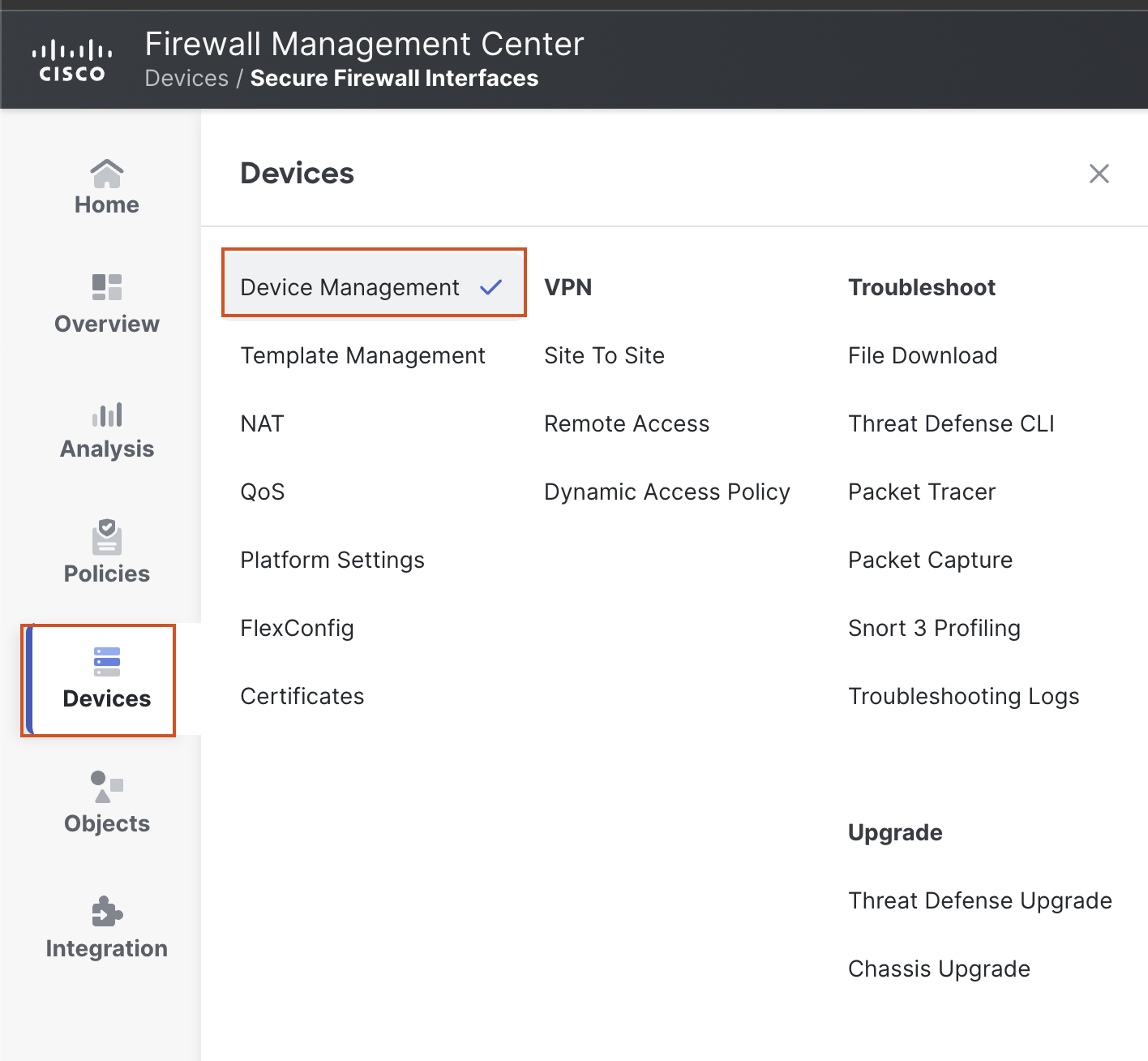
Go to Device > Device Management and click the pencil (edit) icon next to NGFW1.
-
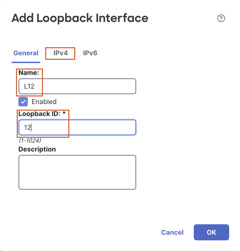
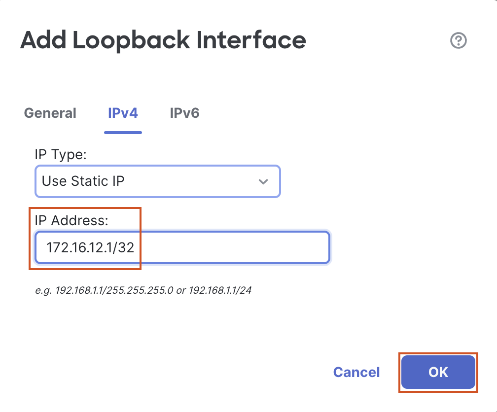
Click on Add Interfaces > Loopback Interface to add a new loopback interface.
- In the pop up box, configure the following details:
- In the General Tab
- Name: L12
- Loopback ID: 12
- In the IPv4 Tab
- IP Address: 172.16.12.1/32
- In the General Tab
- Click on OK to save the interface.
- In the pop up box, configure the following details:
-
Click Add Interfaces > Loopback Interface to add another loopback interface.
- In the pop up box, configure the following details:
- In the General Tab
- Name: L13
- Loopback ID: 13
- In the IPv4 Tab
- IP Address: 172.16.13.1/32
- In the General Tab
- Click on OK to save the interface.

- In the pop up box, configure the following details:
-
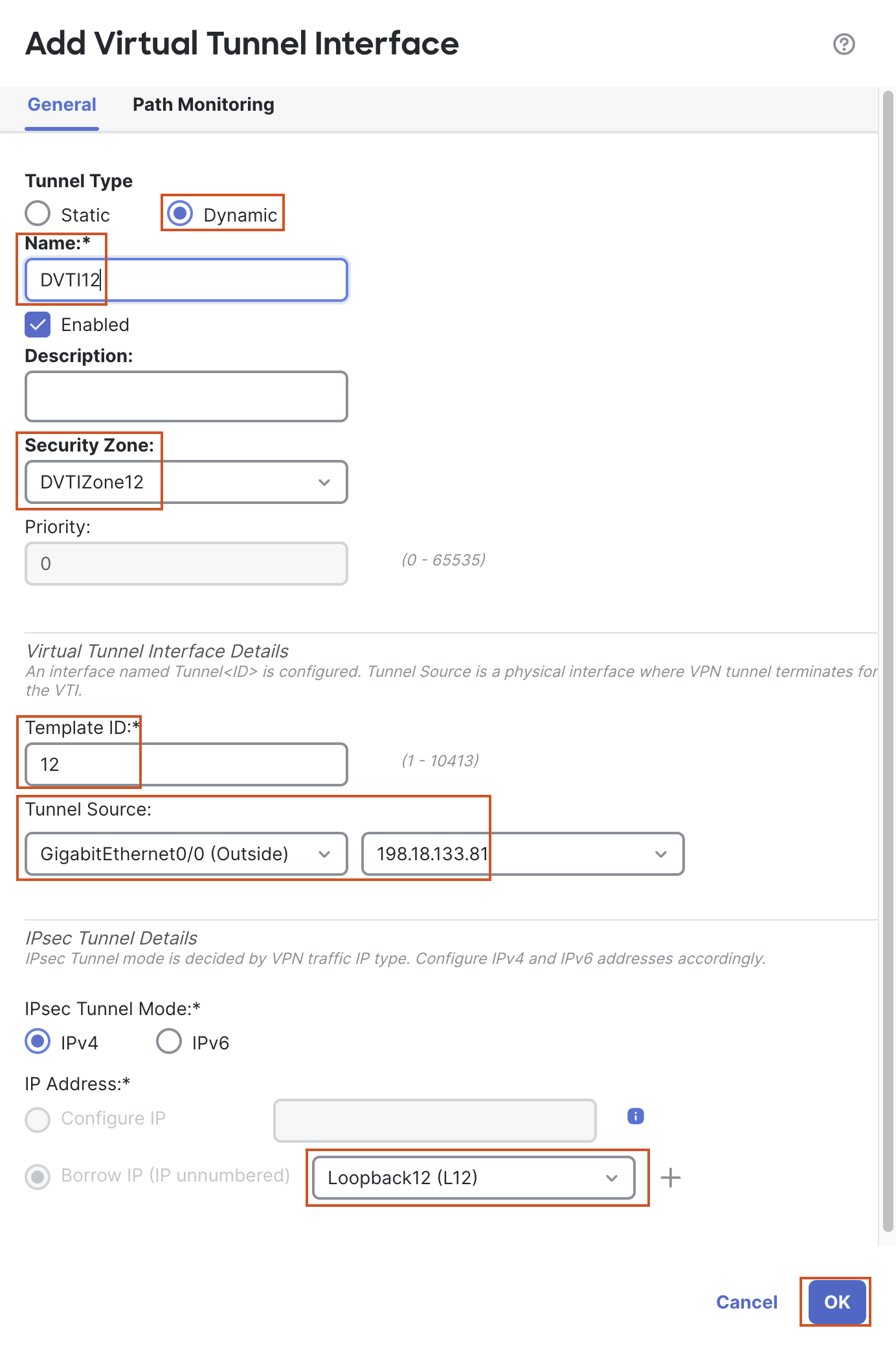
Click Add Interfaces > Virtual Tunnel Interface to add a VTI.
- In the pop up box, configure the following details:
- Tunnel Type: Dynamic
- Name: DVTI12
- Security Zone: In the drop-down, click New...
- Add a new zone named "DVTIZone12" and click OK.
- Template ID: 12
- Tunnel Source: GigabitEthernet0/0 (outside)
- Tunnel Source Address: 198.18.133.81 (outside interface IP address, available in the drop down once the tunnel source is selected)
- IP Address: Borrow IP (IP unnumbered) will be selected by default. From the drop down next to it, select Loopback12 (L12)
- Click OK to save the DVTI.
- In the pop up box, configure the following details:
Note
For a DVTI, we cannot configure an IP address, a DVTI must borrow an IP address from an interface. Hence, "Borrow IP" option is selected by default and greyed out, since we cannot change this option.
- Click Add Interfaces > Virtual Tunnel Interface to add another VTI.
- In the pop up box, configure the following details:
- Tunnel Type: Dynamic
- Name: DVTI13
- Security Zone: In the drop-down, click New...
- Add a new zone named "DVTIZone13" and click OK.
- Template ID: 13
- Tunnel Source: GigabitEthernet0/0 (outside)
- Tunnel Source Address: 198.18.133.81 (outside interface IP address, available in the drop down once the tunnel source is selected)
- IP Address: Borrow IP (IP unnumbered) will be selected by default. From the drop down next to it, select Loopback13 (L13)
- Click OK to save the DVTI.
- In the pop up box, configure the following details:
- Click Save to save the changes made to the interfaces.

Task 2 - Configure VRFs on NGFW1
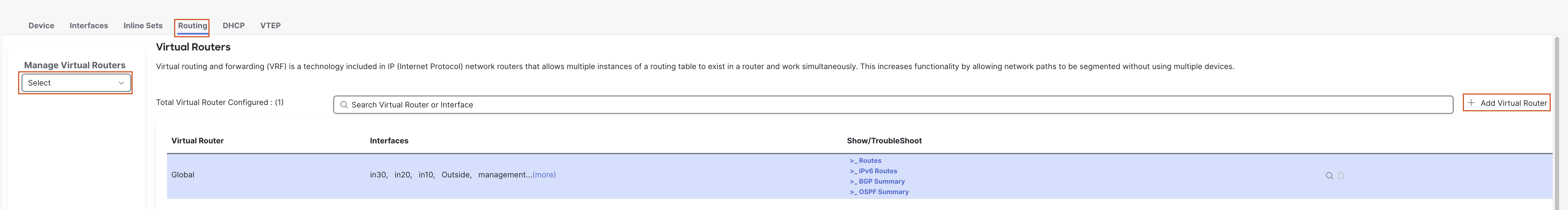
- You should still be editing the device NGFW1 (otherwise, go to Device > Device Management and click the pencil (edit) icon next to NGFW1). Go to the Routing tab.
- In the left bar, click on Manage Virtual Routers.
- Click + Add Virtual Router to add a VRF.
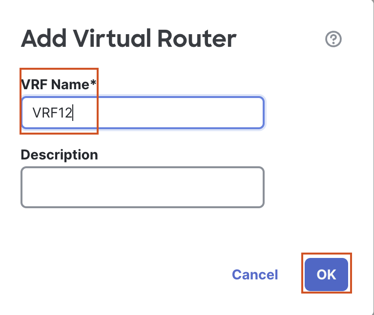
- In the pop up box, enter the Name "VRF12".
- Click on OK to save the new VRF.
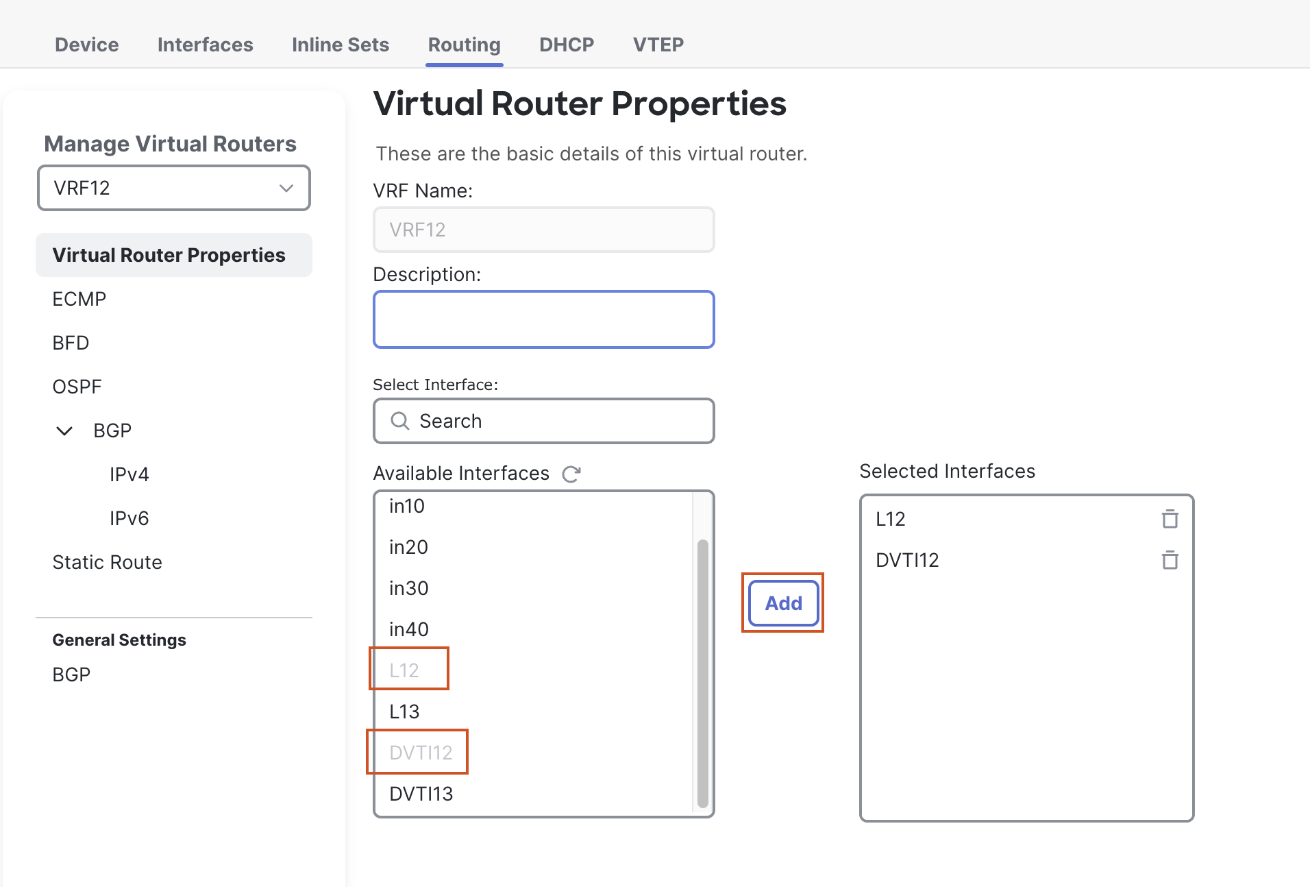
- A new page will open up to configure Virtual Router Properties.
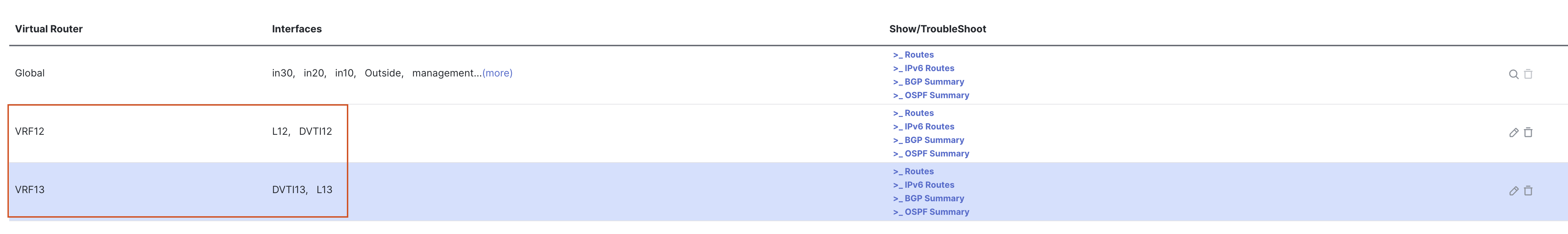
- From the Available Interfaces section, select L12 and click on Add to move it to the Selected Interfaces section.
- Then select DVTI12, and click on Add to move it to the Selected Interfaces section.
- Click + Add Virtual Router to add a VRF.
- Add a second VRF by first clicking on Manage Virtual Routers in the left bar.
- Click on + Add Virtual Router to add another VRF.
- In the pop up box, enter the Name "VRF13".
- Click on OK to save the new VRF.
- A new page will open up to configure Virtual Router Properties.
- From the Available Interfaces section, select L13 and click on Add to move it to the Selected Interfaces section.
- Then select DVTI13, and click on Add to move it to the Selected Interfaces section.
- Click on + Add Virtual Router to add another VRF.
- Click on Save to save the changes.
Task 3 - Configure VPN Topologies using SDWAN Wizard
-
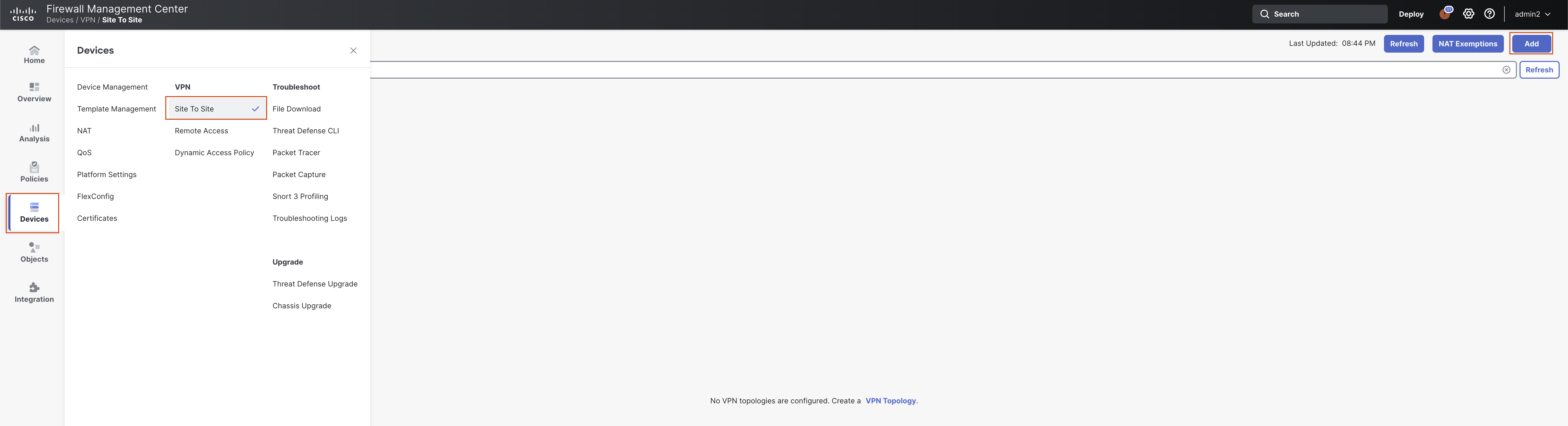
Navigate to Devices > VPN > Site to Site and click Add.
-
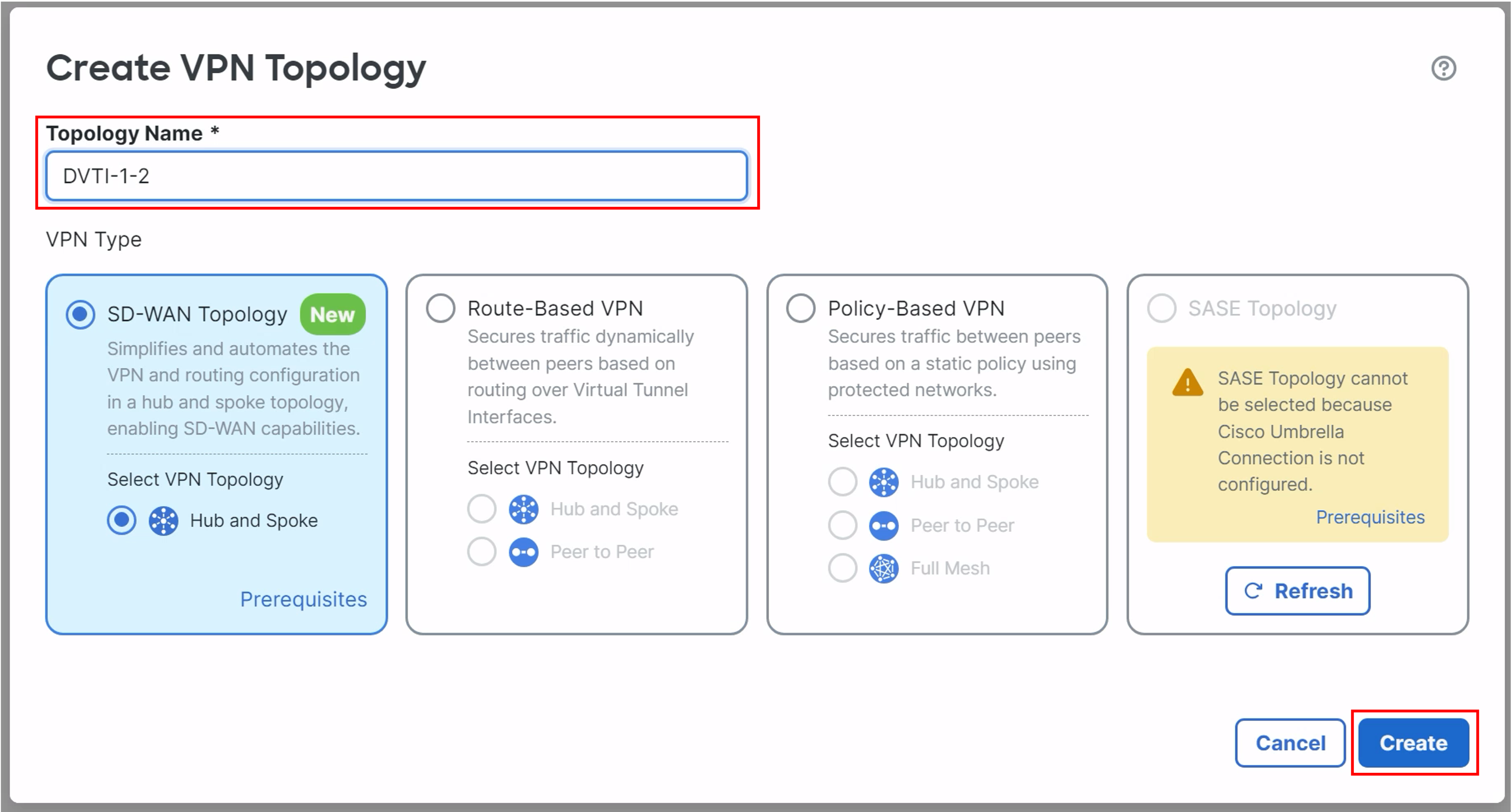
In the pop-up box, configure the following details:
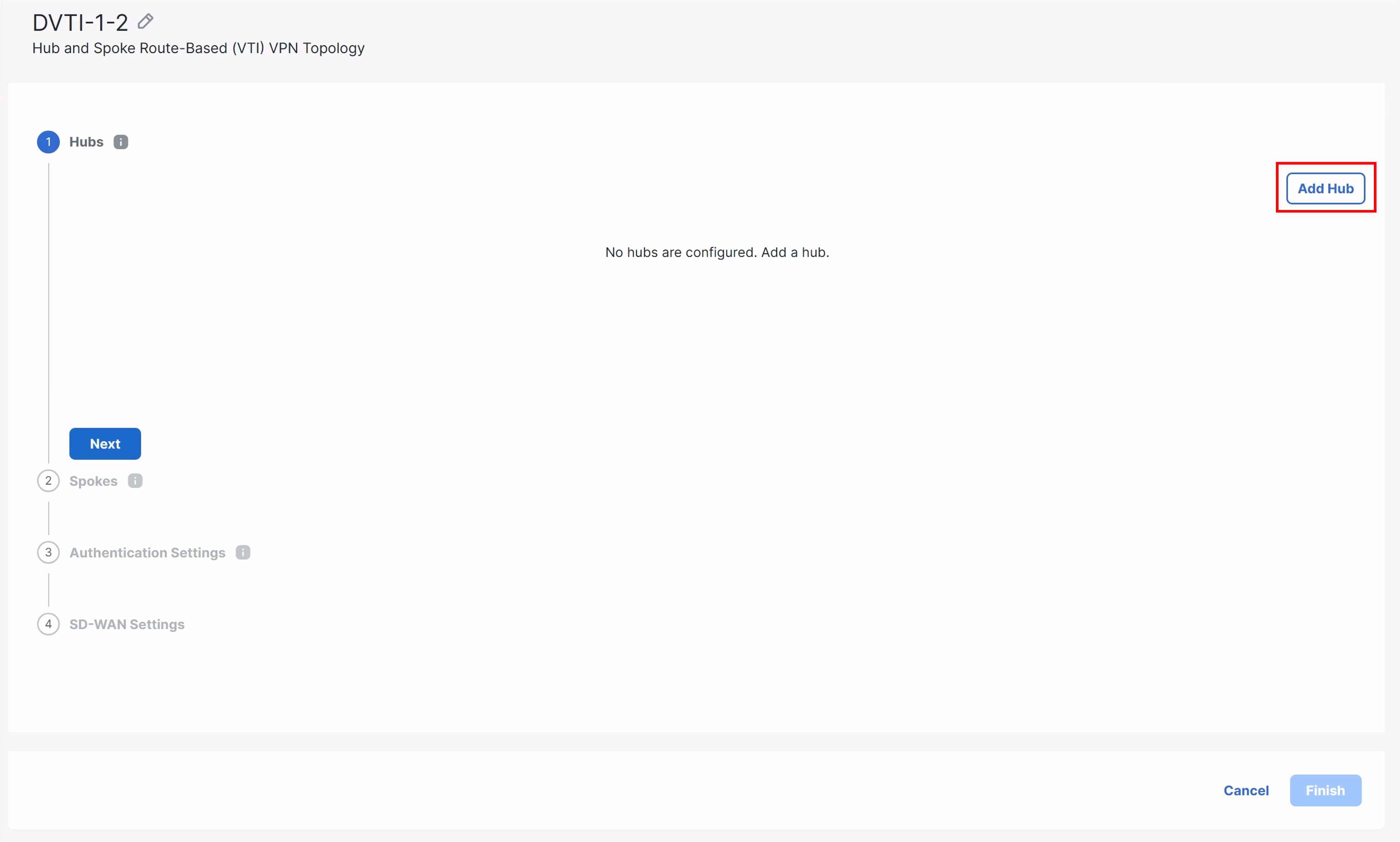
- Topology Name: DVTI-1-2.
- Ensure the Radio Button for SD-WAN Topology is selected.
- Ensure the radio button for Hub and Spoke is selected.
- Click Create.
- Click Add Hub on the right-most side of the widget.
-
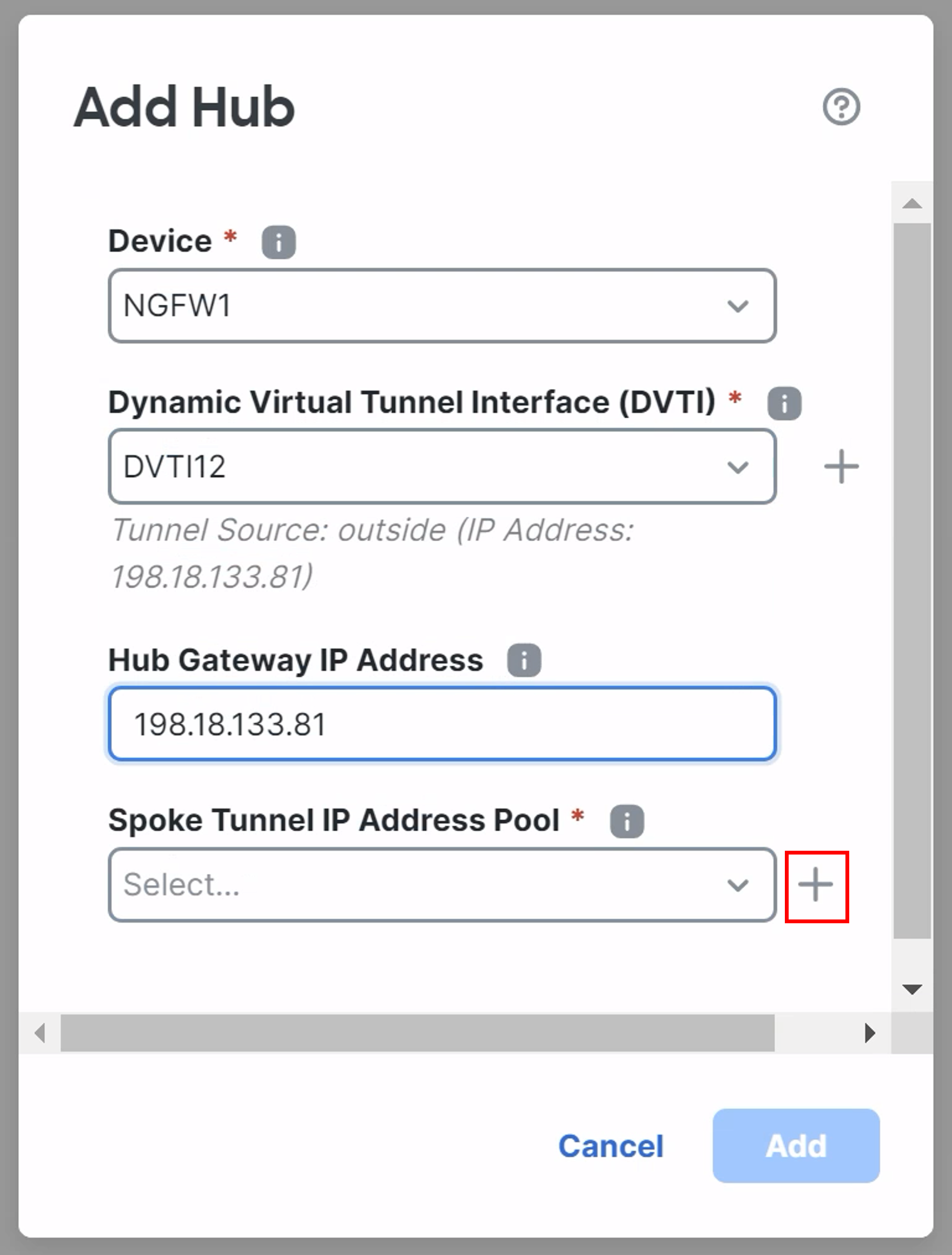
In the pop-up box, configure the following details:
-
Device: NGFW1
-
Dynamic Virtual Tunnel Interface: DVTI12
-
Hub Gateway IP Address will be automatically filled.
-
Click on the + icon next to the Spoke Tunnel IP Address Pool.
-
-
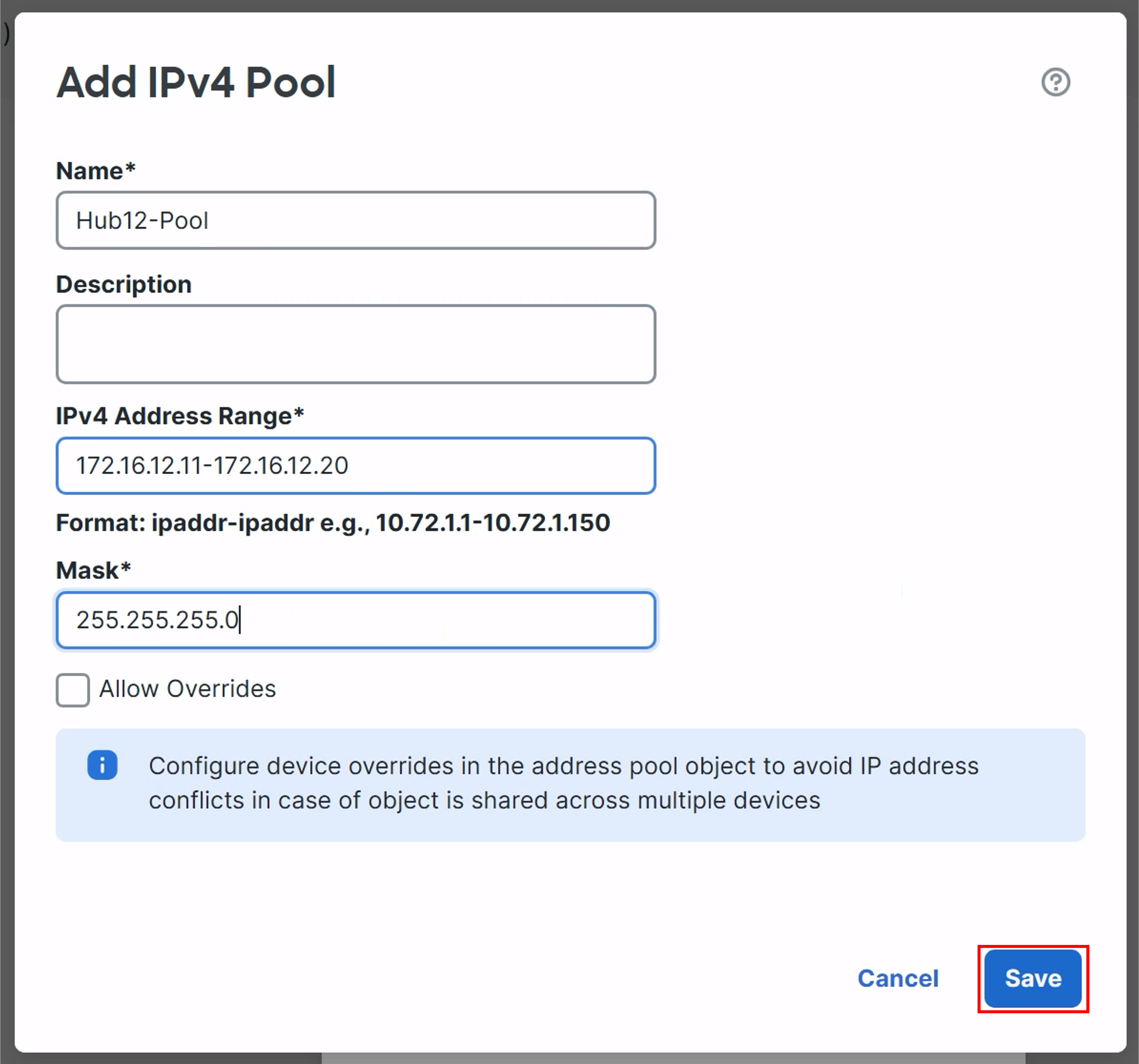
Fill this below details to Add IPv4 Pool
- Name: Hub12-Pool
- IPv4 Address Range: 172.16.12.11-172.16.12.20
- Mask: 255.255.255.0
- Click Save.
- Ensure the newly created Hub12-Pool is selected as the Spoke Tunnel IP Address Pool.
- Click Add.
-
Click Next to add Spokes.
-
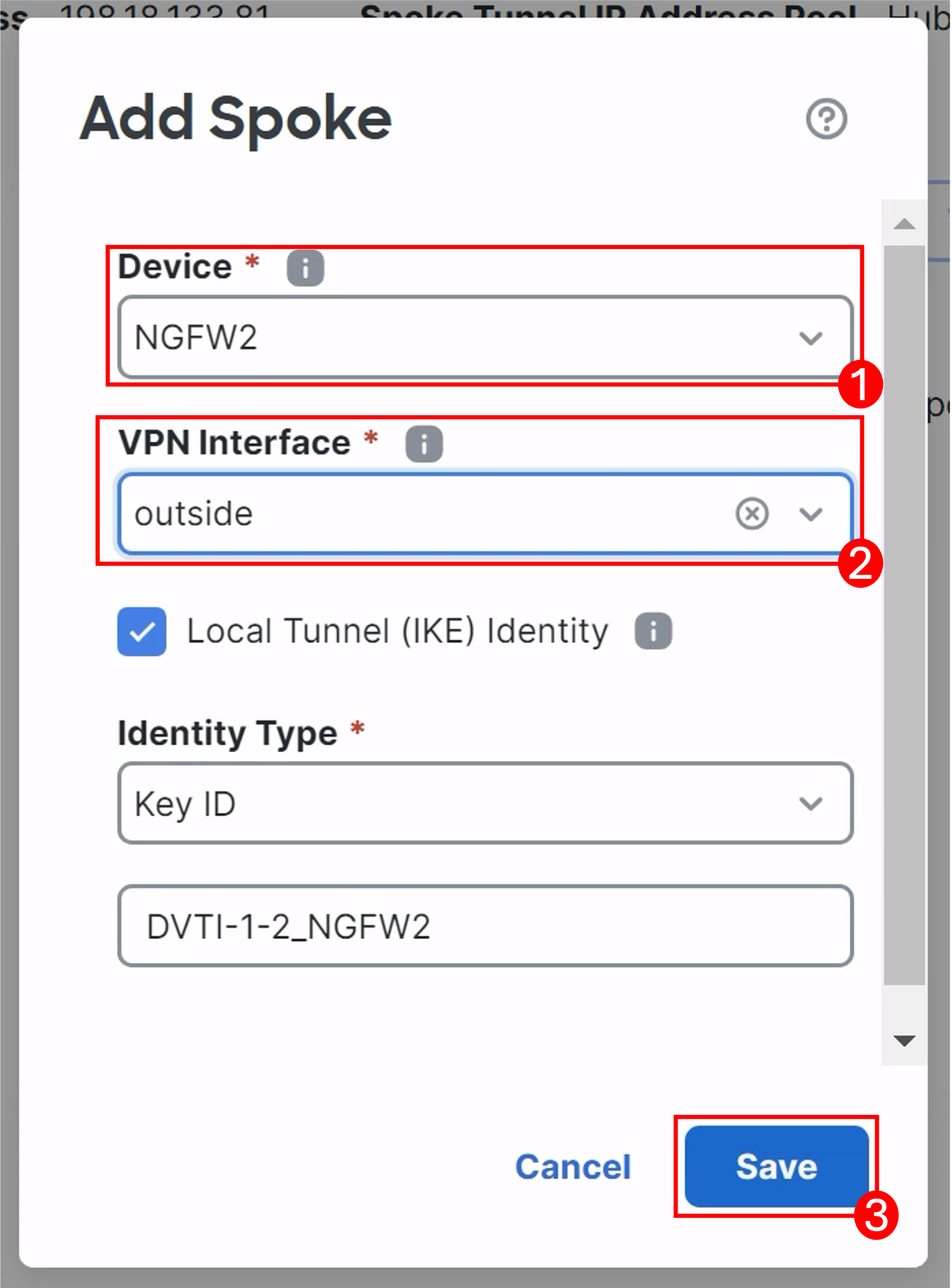
Click Add Spoke.
- Select NGFW2 from Device dropdown.
- Select outside from the VPN Interface dropdown.
- Leave the rest as default and click Save.
-
-
-
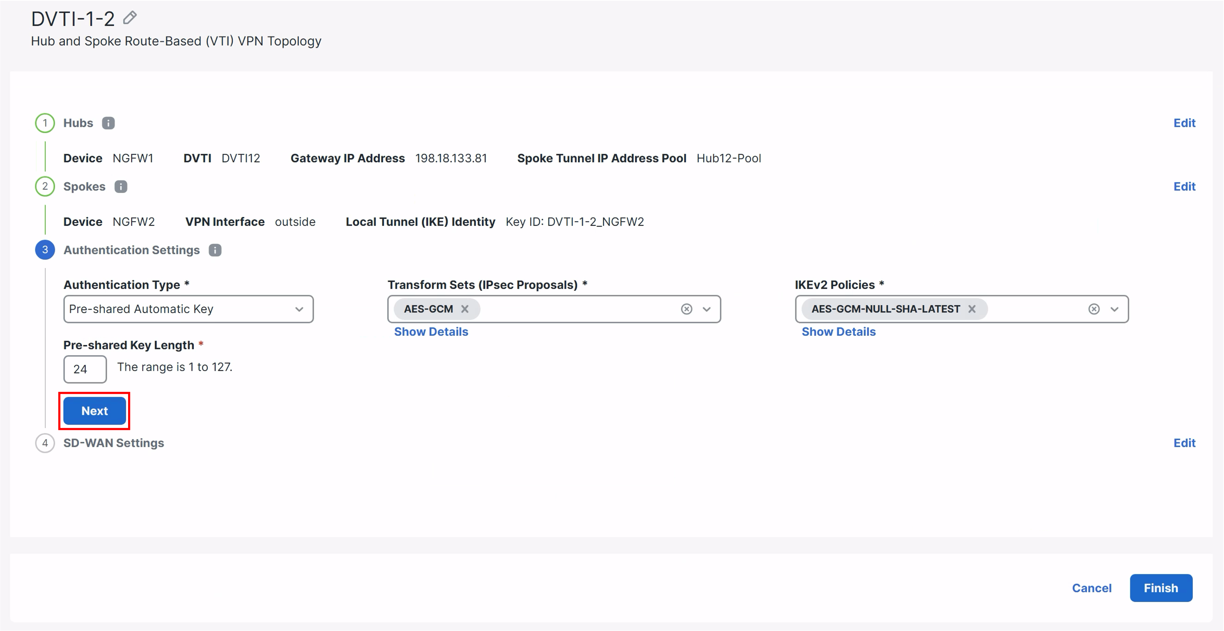
Click Next again.
- The authentication type, Transform Sets and IKEv2 Policies are already filled. Review the settings and click Next.
-
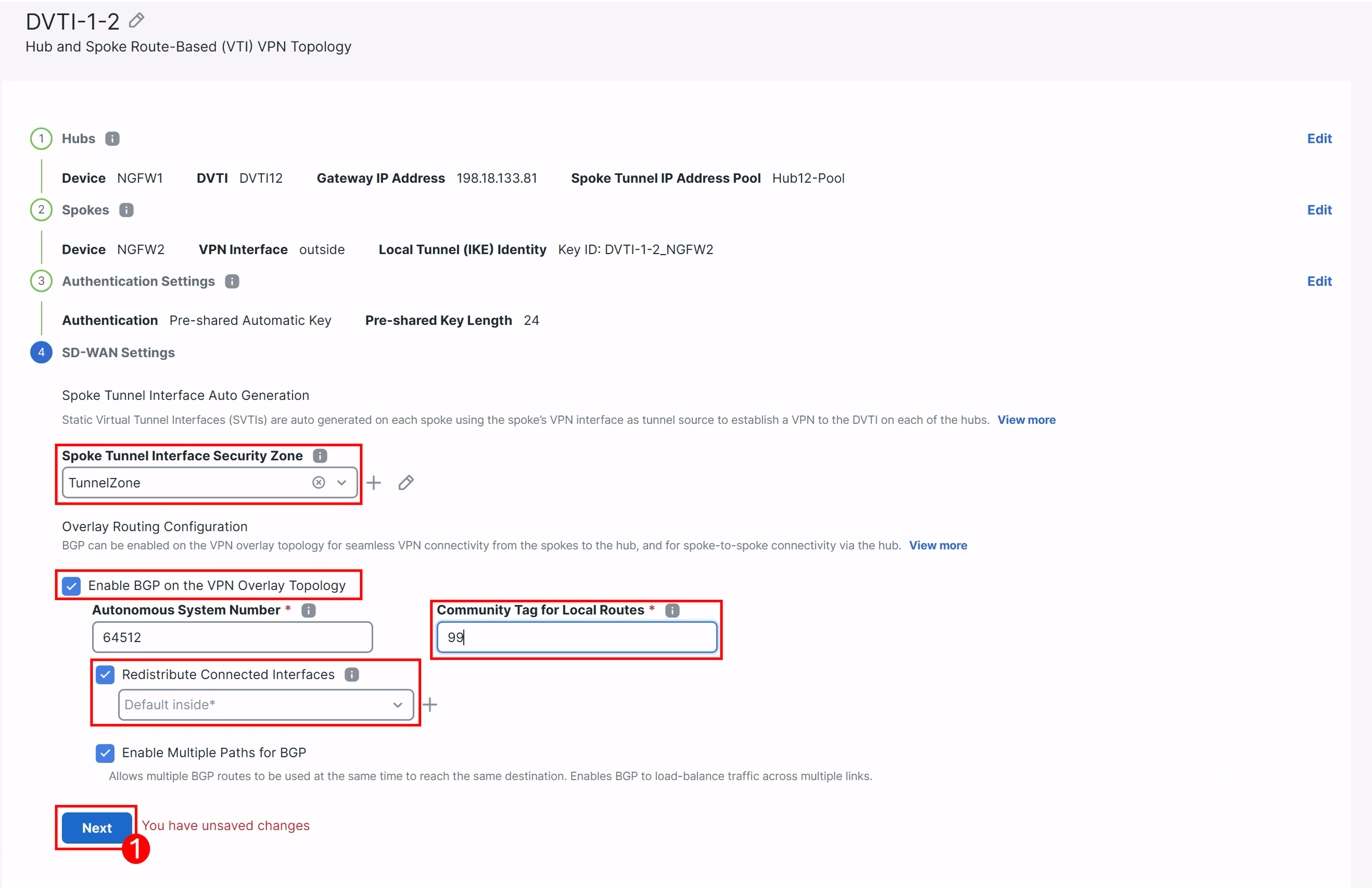
For Spoke Tunnel Interface Security Zone: Click the + icon next to the drop down.
- Add a new zone named TunnelZone.
- Interface Type : Routed.
- Click Save.
-
Ensure TunnelZone is selected as the Spoke Tunnel Interface Security Zone.
-
Click the checkbox for Enable BGP on the VPN Overlay Topology.
- For Community Tag for Local Routes : Fill 99
- Check the Redistribute Connected Interfaces box.
- Leave everything else default.
-
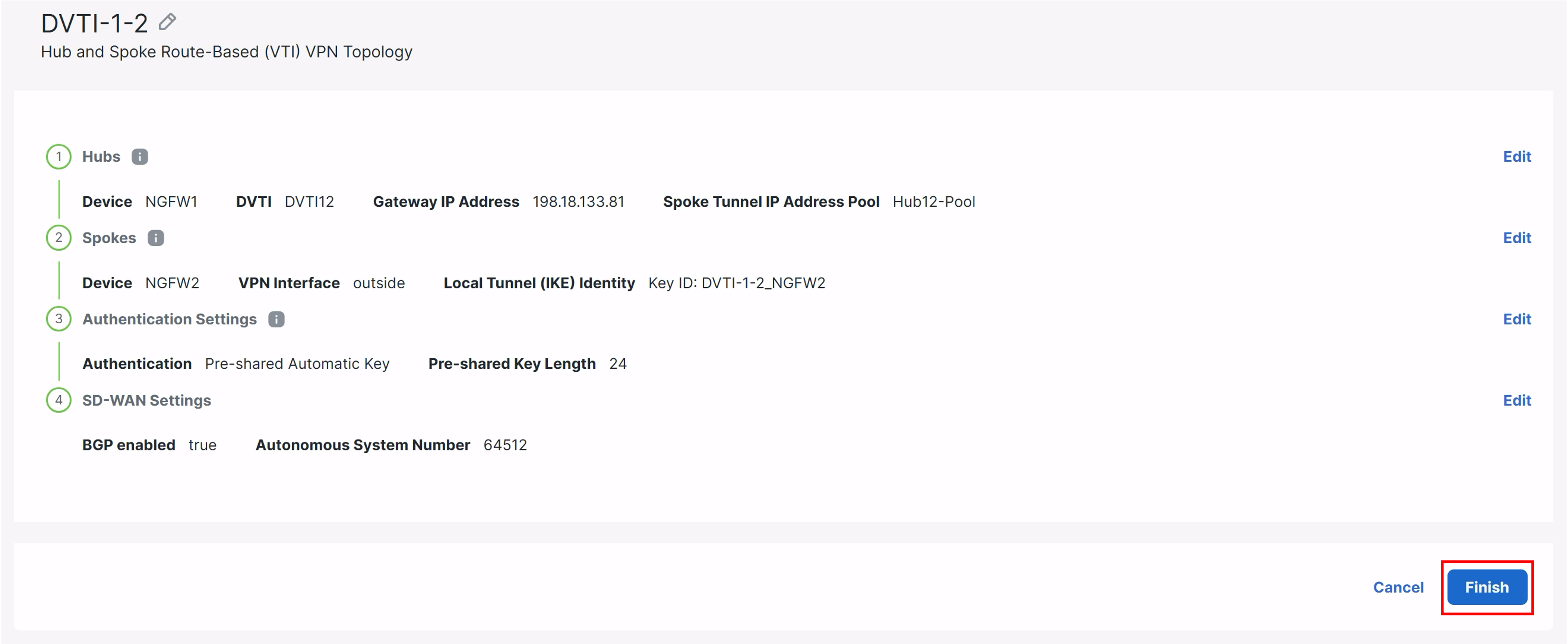
Ensure your configuration matches what you see below and then click Next:
-
Click Finish.
-
Click Add again to add another VPN topology and perform the same steps as the previous SD-WAN Topology with the following configuration parameters:
- Topology Name : DVTI-1-3
- VPN Type : SD-WAN Topology and ensure Hub and Spoke is selected.
- Click Create.
-
Click Add Hub
- Device : NGFW1
- Dynamic Virtual Tunnel Interface(DVTI) : DVTI13
- Hub Gateway IP Address will be automatically filled.
-
Click on the + icon next to the Spoke Tunnel IP Address Pool and fill in the below details to the Add IPv4 Pool pop-up:
- Name: Hub13-Pool
- IPv4 Address Range: 172.16.13.11-172.16.13.20
- Mask: 255.255.255.0
- Click Save.
- Ensure the newly created Hub13-Pool is configured as the Spoke Tunnel IP Address Pool.
- Click Add.
-
Click Next.
-
Click Add Spoke.
- Select NGFW3 from Device dropdown
- Select outside for VPN Interface.
- Leave the rest as default and clickSave.
-
-
Click Next and leave the authentication type, Transform Sets and IKEv2 Policies as default.
- Review the settings and click Next.
-
In the Spoke Tunnel Interface Security Zone dropdown, select TunnelZone.
-
Click the checkbox for Enable BGP on the VPN Overlay Topology.
- For Community Tag for Local Routes : Fill 99
- Click the checkbox next to Redistribute Connected Interfaces.
- Leave everything else default.
- Click Next.
-
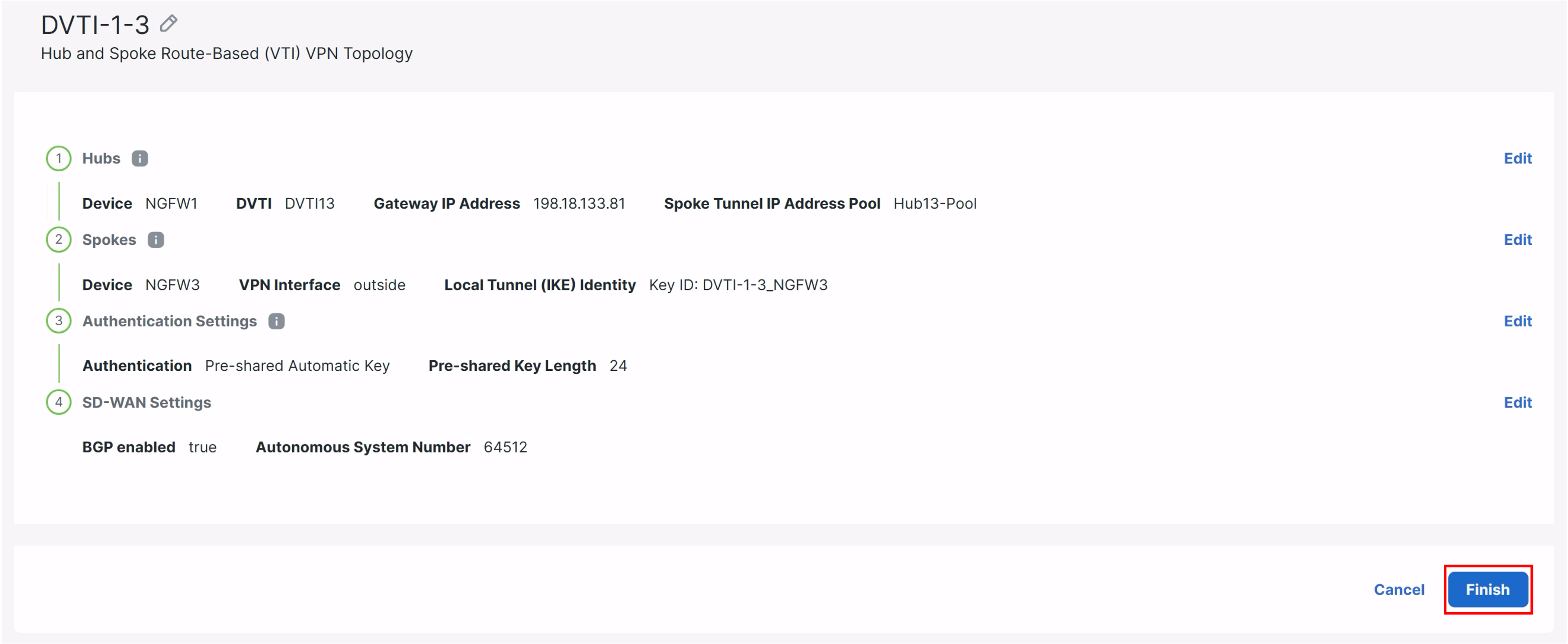
Ensure your configuration matches what you see below and then click Finish:
Deployment
- Click Deploy > Deploy All and wait for the changes to be pushed to the devices.
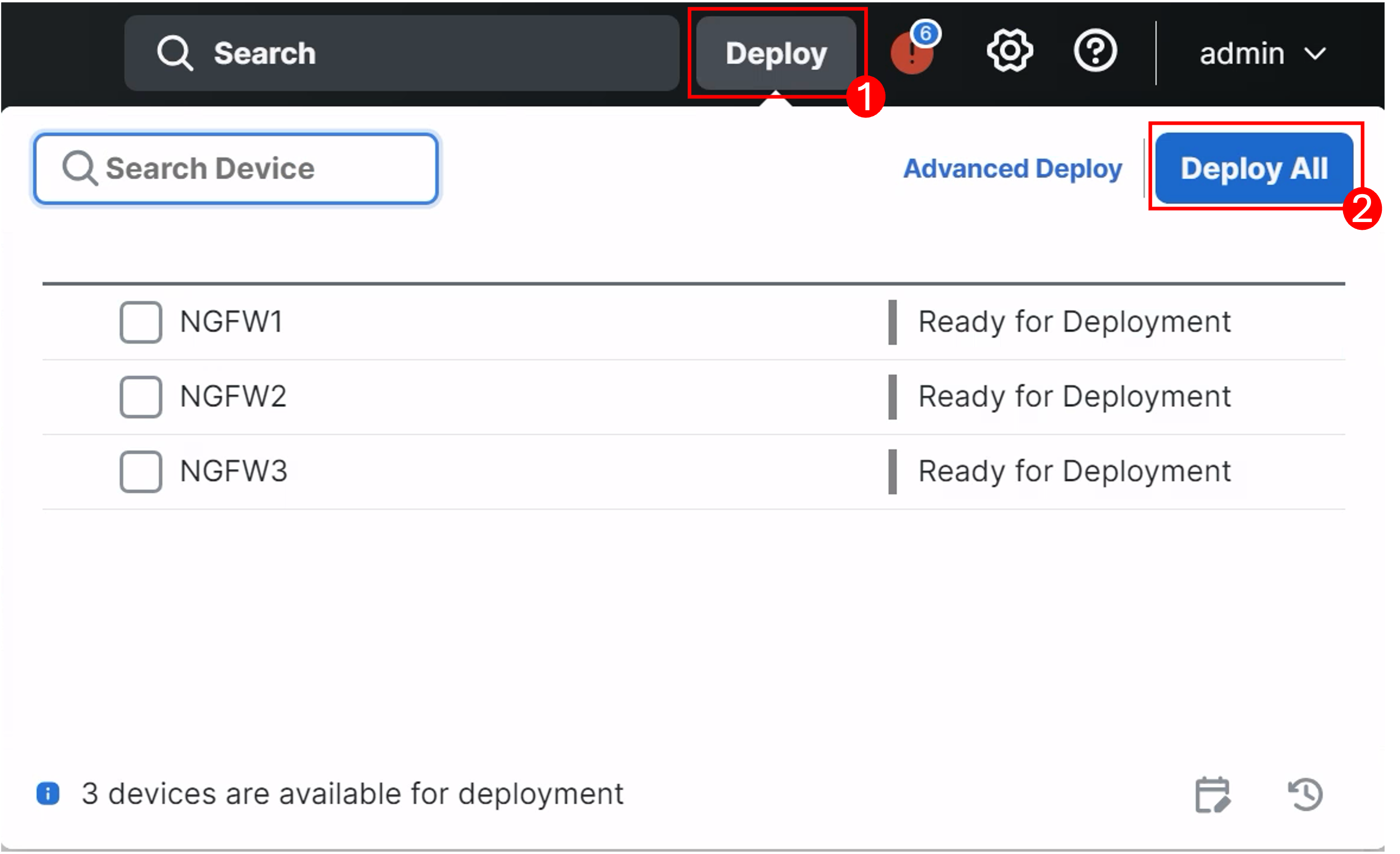
Wait!
You will get a warningThe changes to Virtual Routers may cause traffic disruption. This is expected as we have configured new VRFs. Click the checkbox next to "Ignore Warnings" and click Deploy to push the changes.
Verification via the CLI
-
Connect to the CLI of NGFW1 using the quick launch under the NGFW Console Access section. The credentials will be pre-populated.
-
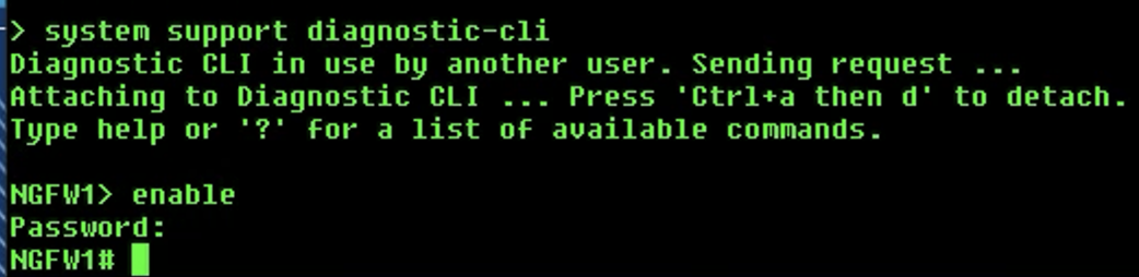
Connect to the diagnostic cli by using the
system support diagnostic-clicommand.- Use the
enablecommand to log into enable mode (privileged mode) and leave the password as blank.
- Use the
-
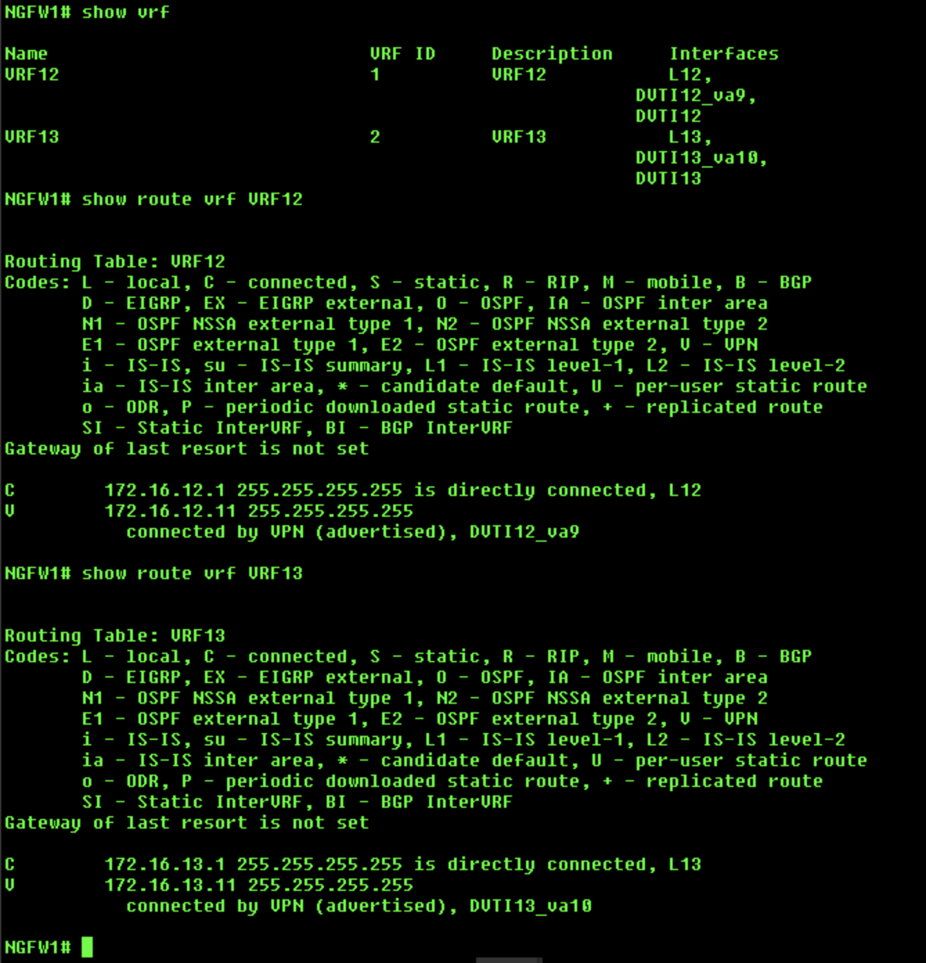
Use the
show vrfcommand to see the configured VRFs and the interfaces associated with them. -
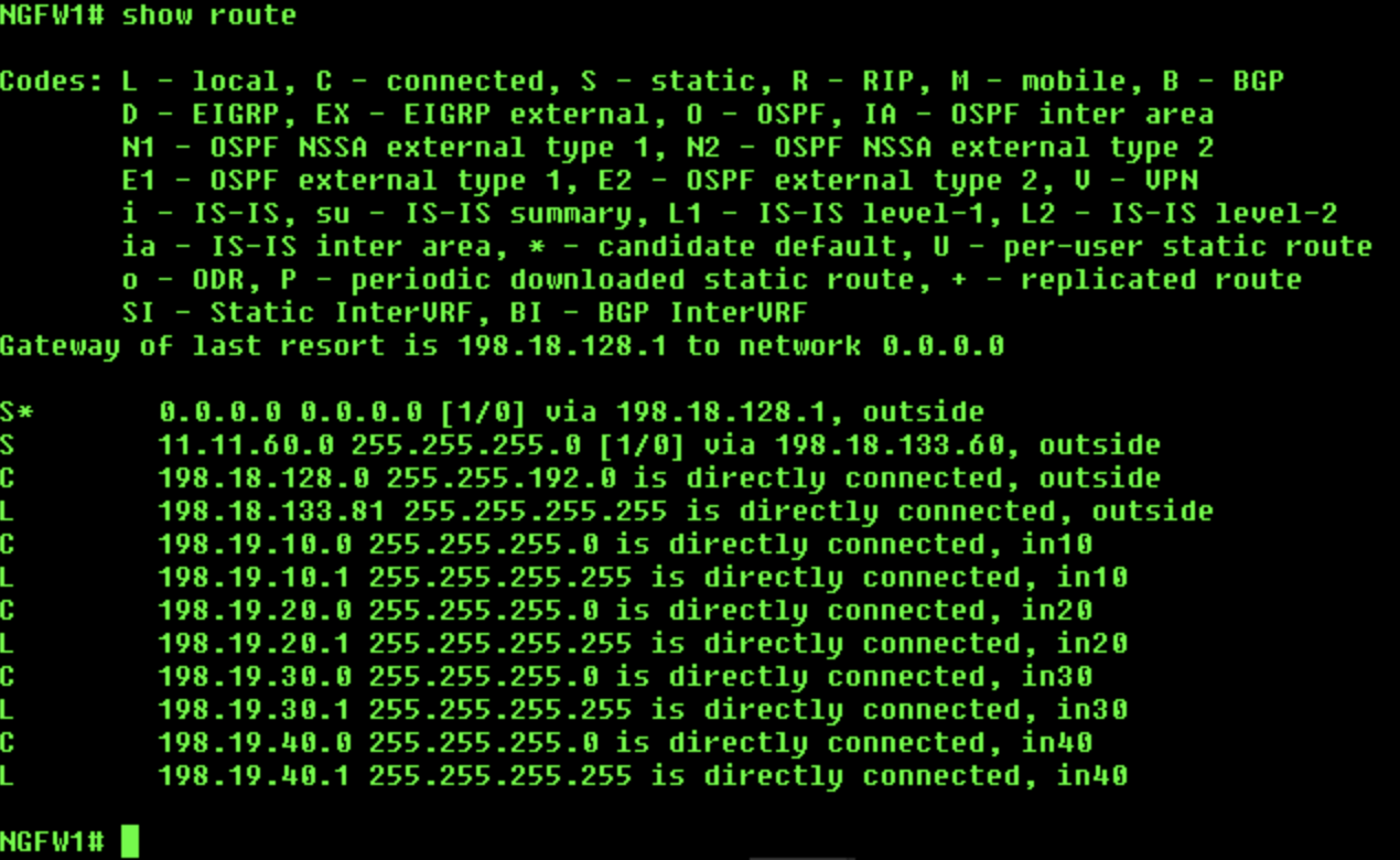
Use the
show routecommand to check the routes in the global routing table. We will not see the two loopback and DVTI interfaces in the routing table. -
Use the
show route vrf <vrf name>command to check the routes for both VRFs. We will see the routes for respective loopback and DVTI interfaces.
-
Check connectivity using the following
pingcommands:-
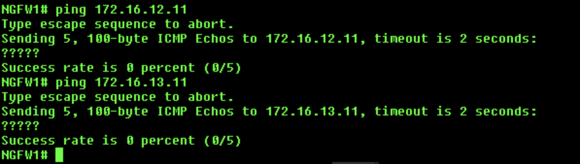
Global Router:
ping 172.16.12.11- This ping will failping 172.16.13.11- This ping will also fail
-
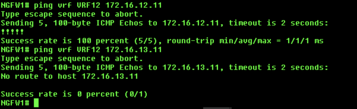
VRF12:
ping vrf VRF12 172.16.12.11- This ping will succeedping vrf VRF12 172.16.13.11- This ping will fail
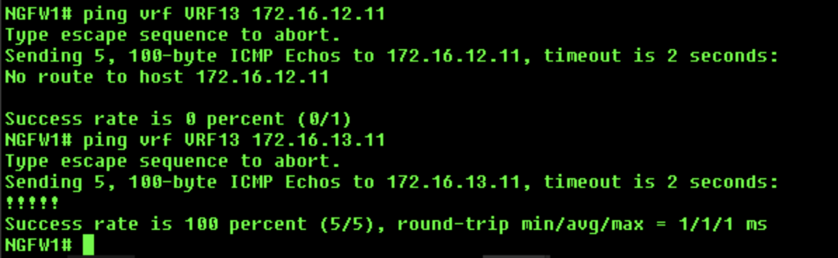
iii. VRF13:
a.
ping vrf VRF13 172.16.12.11- This ping will fail
b.ping vrf VRF13 172.16.13.11- This ping will succeed -
Success
In the next scenarios you will do the same verification using the SD-WAN Summary Dashboard as well as the Site to Site VPN Dashboard.
Tell us how we are doing
We are doing our best to ensure the scenarios in this lab guides are useful, clear and work as expected.
Please share your thoughts to help us improve or fix any problems you may run into..
Click here to provide your feedback or report an issue with this guide