SD-WAN Wizard
Introduction
Building on top of previous releases for SD-WAN features, Cisco Secure Firewall Release 7.6 introduces a simplified and automated guided wizard for route based hub and spoke topology in an SD-WAN deployment.
This significantly reduces the configuration steps and simplifies the creation and management of SD-WAN topologies in Firewall Management Center, thus enabling administrators to easily configure VPN tunnels between the centralized headquarters and remote branch sites.
NOTE
This feature is supported with:
- Secure Firewall Management Center (FMC) running release 7.6, and
- Secure Firewall Threat Defense devices running
- 7.6 for Hub devices, and
- 7.3 for Spoke devices
- No additional licenses. Requires export-controlled license or Crypto-compliance to be enabled to use the new SD-WAN wizard for VPN tunnel configuration.
Background Information
Prior to 7.6 release, administrators configured the hub and spoke topologies using the Site to Site VPN wizard which requires:
- Configuring Static Virtual Tunnel Interface (SVTI) on spokes manually
- Configuring unique IP addresses for each of the VTIs, which can be challenging for a large enterprise with hundreds or thousands of spokes
- Configuring some attributes of the tunnel interfaces and VPN authentication settings manually
- Navigating through different sections of the UI to configure Virtual Tunnel Interfaces (VTIs), VPN topology, and routing configuration
- Adding spokes one at a time to the VPN topology
- Configuring overlay routing configuration manually
This feature addresses these challenges and simplifies the process by:
- Creating SVTIs on the spoke automatically
- Automating IP address assignment for spoke SVTIs via the Hub
- Automating the relevant tunnel interface configuration and VPN authentication settings
- Simplifying the tunnel interfaces, VPN topology and overlay configuration in a single page
- Supporting bulk addition of spokes
- Automating overlay routing parameters for spoke to spoke and spoke to hub communication
How it works
This section demonstrates the high level overview of the steps to configure SD-WAN wizard:
- Hub Configuration
The wizard requires only the following three parameters for Hub Configuration:- Selecting FTDs which will be designated as the Hub in this SD-WAN topology.
Either single or dual hub is supported. - Configuring Dynamic Virtual Tunnel Interface (DVTI) associated to the hub devices
- Configuring IP Pool, to automate IP address assignment of SVTI interfaces on Spoke devices
All DVTI interface parameters are auto populated which can be modified if required.
Hub Gateway IP address is auto populated based on the tunnel source IP address. If the Hub is behind a NAT device, then configure the Hub's public IP address in this field.
- Selecting FTDs which will be designated as the Hub in this SD-WAN topology.
- Spoke Configuration
In this step, select the FTDs to be configured as Spoke and the VPN interface (i.e. Tunnel Source or the Underlay Interface)
This step automates the SVTI interface on Spoke for each Hub and FMC assigns IP to SVTI interfaces using the IP pool configured in the Step 1 (iii) above, and lastly, auto generates the unique Local Tunnel ID for each spoke. - Authentication Settings
This step covers the automated generation of pre-shared keys (PSK) and auto generation of IKE and IPSec policies including authentication encryption and authentication algorithms.
PSKs can be modified if required. Additionally, certificate authentication is also supported. - SD-WAN Settings
This step covers the security zone for spoke SVTIs and allows configuration of overlay routing using BGP.
SVTIs on spoke are automatically assigned the security zone configured in this step rather configured manually by the administrator and auto generates BGP neighbor and route-map configuration for overlay interface and networks.
Overlay Routing Enhancements
Route Reflector Support in internal Border Gateway Protocol (iBGP)
One of the key considerations in the SD-WAN topology is to allow spoke to spoke communication. To implement spoke to spoke routing distribution in iBGP deployment via Hub without requiring full mesh connectivity, the wizard brings in support for Route Reflector.
This allows the hub(s) to be configured as route reflector while the spokes are configured as route reflector clients and not only allows the spoke to spoke communication, but also determines the best routing path based on the spokes’ active and backup tunnels.
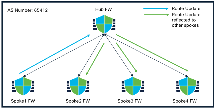
Route Reflector Feature within SD-WAN Topology
Using the route-reflector enhancement, the hub can re-advertise routes learned from one spoke to another spoke that has same AS number. This is supported for IPv4 and IPv6 as well.
AS-Override Support in external Border Gateway Protocol (eBGP)
Note
AS number is a unique number for a network with a single routing policy. BGP uses AS numbers to identify networks. The spoke's BGP neighbor configuration is generated based on the corresponding hub’s AS number. Range is from 0 to 65536.
In a dual hub topology, spokes and hub in a particular region are part of same AS number while spokes and hub in different region are part of another AS number. Also, spokes are configured to establish additional tunnels to the hub in a different AS number for redundancy.
The SD-WAN wizard brings in BGP support for AS Override feature that allows:
- Spokes that are part of an AS to learn the routes of other spokes in same AS connected to a hub in different AS
- Spokes that are part of an AS to learn the routes of other spokes in different AS connected to a hub within their own AS
Lets look at an example using scenario 1, assuming due to failure on the hub site, the spokes are not able to communicate to the hub in their own region and one of the spoke wants to communicate to another spoke in same region but they are currently connected to the hub in another region.
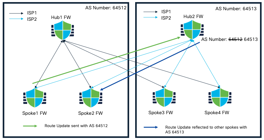
AS-Override Feature within SD-WAN Topology
In this case, a spoke connected to a hub in a different region intends to learn routes of another spoke. Due to the same AS number in the AS path, the routes will not be installed. AS Override feature addresses this challenge by replacing the AS number of originating router with AS number of the sending BGP router.
Prerequisites
Before proceeding further with configuration, please ensure the following:
- FTDs must have an internet-routable public IP address
- Assign appropriate logical names and IP addresses to the interfaces of the FTDs. E.g. use inside for the LAN interface and outside for the WAN or internet facing interface
- Enroll the certificates on the hub and spoke devices if using certificate based authentication
- Configure routing, NAT, and AC policies to ensure underlay connectivity between the devices
Configuration
While the SD-WAN wizard can be used to deploy various types of topologies, some of the key deployment scenarios that this feature can simplify and automate are:
- Dual Hubs within the same autonomous systems (AS) and Spokes, all with single ISP
- Dual Hubs in different AS and Spokes, all with single ISP
- Dual Hubs within same AS and Spokes, all with dual ISP
- Dual Hubs in different AS and Spokes, all with dual ISP
The following configuration example is based on scenario number 3.
Topology
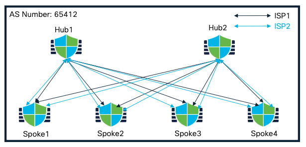
Dual Hubs within same AS and Spokes, all with dual ISP
Starting the SD-WAN Wizard
-
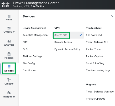
Choose Devices > Site To Site , and click Add
-
Click Add

-
Enter a name for the SD-WAN VPN topology in the Topology Name field, e.g. ISP1_Topology
-
Click Create
Hub Configuration
-
Click Add Hub.

-
From the Device drop-down list, choose a hub. Please note that the maximum of two hubs can be added.
In this example, we select Hub1 as the Hub.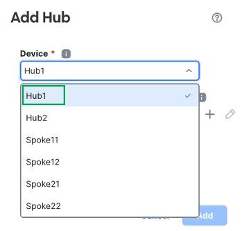
-
Click + next to the Dynamic Virtual Tunnel Interface (DVTI) drop-down list to add a dynamic VTI for the hub.
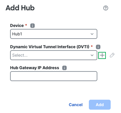
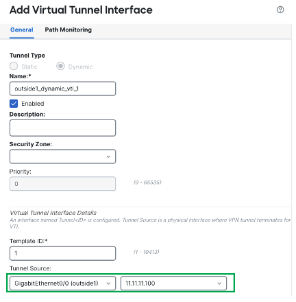
The Add Virtual Tunnel Interface dialog box is prepopulated with default configurations. However, you must configure the Tunnel Source, and the Borrow IP Address.
In this example, Hub1 is pre-configured with Tunnel Source as outside1 interface with IP 11.11.11.100/24.
-
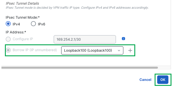
Scroll down and choose a physical or loopback interface from the Borrow IP drop-down list, the dynamic VTI interface inherits this IP address.
This example uses an existing loopback interface Loopback100 with IP 192.168.1.100/32 configured on the Hub1 device for this topology. -
Click Ok.
-
Click Ok again to confirm the VTI interface has been created successfully.
-
In the Hub Gateway IP Address field, enter the public IP address of the hub's VPN interface or the tunnel source of the DVTI to which the spokes connect.
Note
This IP address is auto populated if the interface has a static IP address. If the hub is behind a NAT device, you must manually configure the post-NAT IP address.
In this example, the Hub Gateway IP Address is auto populated as 11.11.11.100, the IP addressed associated to the outside1 interface which is the tunnel source of the DVTI.
-
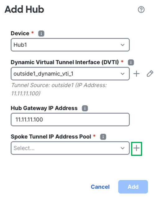
From the Spoke Tunnel IP Address Pool drop-down list, click + to create an address pool.
Note
IP Pool depends on the tunnel mode of the DVTI configuration. If the tunnel mode is IPv4, then the IP Pool must be IPv4 as well. Likewise when the tunnel mode is set to IPv6.
When you add spokes, the wizard auto generates tunnel interfaces, and assigns IP addresses to these interfaces from this IP address pool.
-
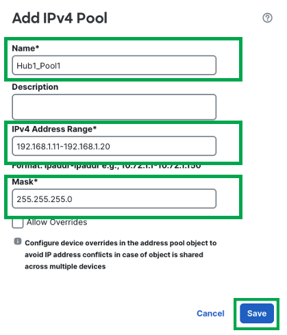
Configure the name of the pool. E.g. Hub1_Pool1
-
Configure the IPv4 Address range.
-
Configure the Mask
-
Click Save
-
-
Click Add to save the hub configuration.
-
To add a secondary hub, click Add Hub.

-
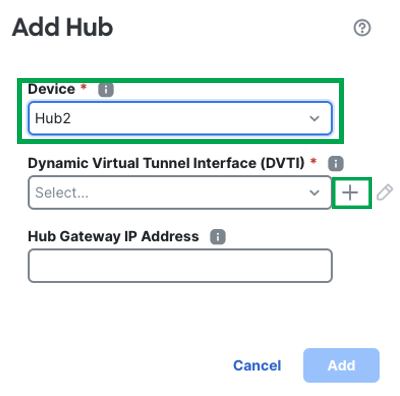
Select the device as Hub2 and click + next to create DVTI.
-
The Add Virtual Tunnel Interface dialog box is prepopulated with default configurations. However, you must configure the Tunnel Source, and the Borrow IP Address.
In this example, Hub2 is pre-configured with Tunnel Source as outside1 interface with IP 11.11.11.200/24.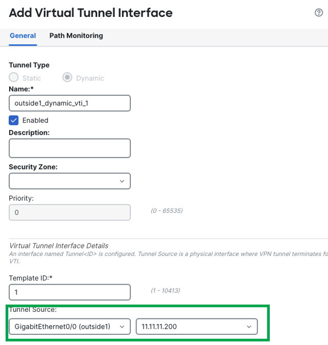
-
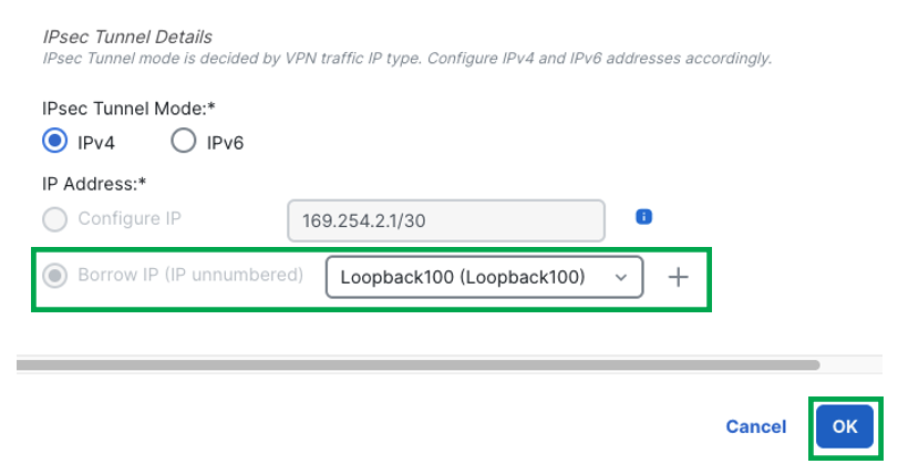
Scroll down and choose a physical or loopback interface from the Borrow IP drop-down list, the dynamic VTI interface inherits this IP address.
This example uses an existing loopback interface Loopback100 with IP 192.168.2.100/32 configured on the Hub2 device for this topology. -
Click Ok
-
Click Ok again to confirm the VTI interface has been created successfully.
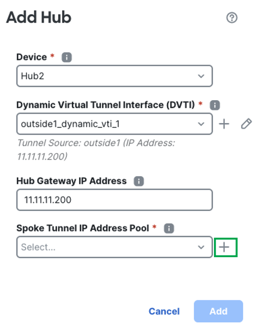
In the Hub Gateway IP Address field, the IP address is auto populated. -
From the Spoke Tunnel IP Address Pool drop-down list, click + to create an address pool.
-
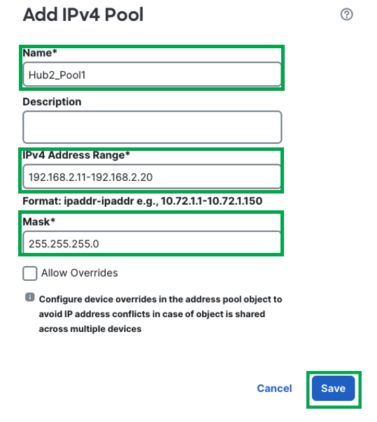
Configure the IPv4 Pool as follows and click Save.
-
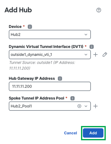
Click Add to save the hub configuration.
Note
Hub devices must be configured with a separate pool to prevent any overlapping of IP address assignment on VTI interfaces on spokes from the hub.
-
Review the Hub configuration. Additionaly, Hub Roles can be swapped by the toggle button
-
Click Next

Spoke Configuration
-
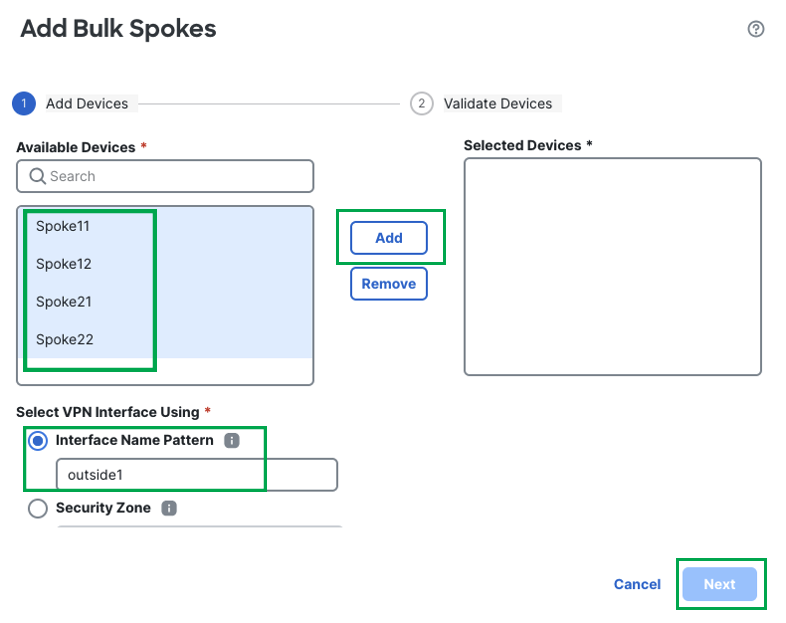
Click Add Spoke to add a single spoke device, or click Add Spokes (Bulk Addition) to add multiple spokes to your topology. In this example, we will use Bulk Addition for Spokes.
-
Click Add Spoke (Bulk Addition)

-
From the Device drop-down list, choose all the spokes and click Add
-
From the VPN Interface drop-down list, choose a WAN-facing or internet-facing physical interface to establish a VPN connection with the hub. E.g. outside or outside1.
Note
In this example, we will use the pattern outside1 so twizard can use the interfaces with matching pattern of logical interface name outside1 and use them as Tunnel Source for the VTI tunnels on the spokes.
-
Click Next
-
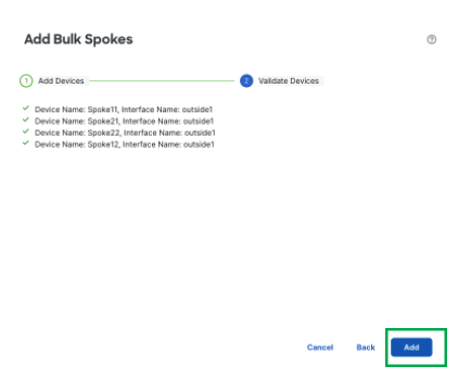
Review the spoke configuration and click Add
-
This completes the spoke configuration. Click Next.
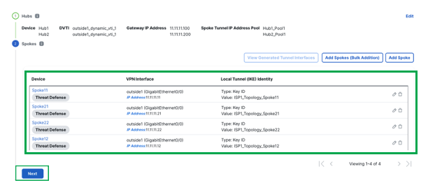
For each spoke, the wizard automatically selects the hub's DVTI as the tunnel source IP address.
Authentication Configuration
For device authentication, you can use a manual pre-shared key, an auto-generated pre-shared key, or a certificate. Configure authentication settings for the devices in the SD-WAN topology:
-
Select Authentication Type as Pre-shared Manual Key

-
Configure the pre-shared key value
-
[Optional] Choose one or more algorithms from the Transform Sets drop-down list.
-
[Optional] Choose one or more algorithms from the IKEv2 Policies drop-down list.
-
Click Next.

Note
When deploying multiple SD-WAN topologies using dual hub configuration, ensure that you use Pre-shared Manual key so the keys are in sync on both the hubs in different topologies.
SD-WAN Settings:
This step primarily involves two main aspects:
- Security Zone of the Spoke devices to be used in the access control policy
- BGP configuration for overlay routing
In this step, FMC configures the spoke devices with auto generation of spoke tunnel interfaces, and BGP configuration of the overlay network.
-
From the Spoke Tunnel Interface Security Zone drop-down list, choose a security zone or click + to create a security zone to which the wizard automatically adds the spokes' auto-generated Static Virtual Tunnel Interfaces (SVTIs).
In this example, a security zone named TunnelZone is pre-configured.

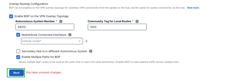
-
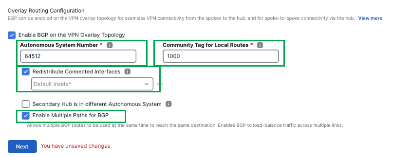
Check the Enable BGP on the VPN Overlay Topology check box to automate BGP configurations such as neighbor configurations between the overlay tunnel interfaces and basic route redistribution from the directly connected inside interfaces of the hubs and spokes.

-
In the Autonomous System Number field, enter an Autonomous System (AS) number. By default, AS number is set to 64512.
-
In the Community Tag for Local Routes field, enter the BGP community attribute to tag connected and redistributed local routes. This attribute enables easy route filtering. This example uses the community tag 1000.
-
Check the Redistribute Connected Interfaces check box and choose an interface group from the drop-down list or click + to create an interface group with connected inside or LAN interfaces for BGP route redistribution in the overlay topology.
-
Check the Enable Multiple Paths for BGP check box to allow multiple BGP routes to be used at the same time to reach the same destination. This option enables BGP to load-balance traffic across multiple links by leveraging ECMP.
-
(Optional) Check the Secondary Hub is in Different Autonomous System check box. This check box appears only if you have a secondary hub in this topology.
-
Click Next.
-
Click Finish to save and validate the SD-WAN topology.
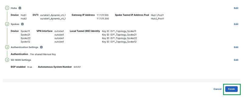
-
The Topology shows as follows:

Note:
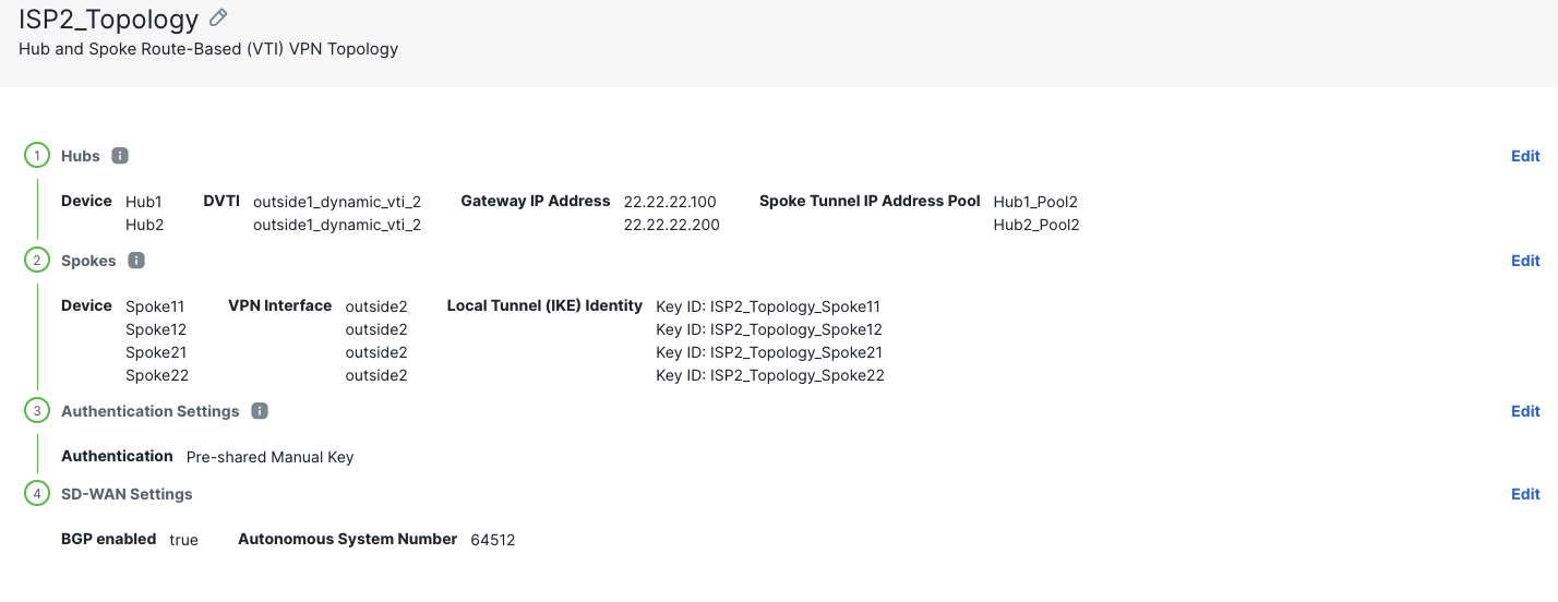
The above example uses ISP1 on both the hubs and all the spokes to create a hub and spoke topology.
To create SD-wan deployment leveraging outside2 interface on the devices, repeat the above steps and create another topology named ISP2_Topology that uses ISP2 on both the hubs and all the spokes.
Ensure that you create the following
- Different loopback interfaces to source the DVTIs on Hub1 and Hub2
- Separate IPv4 Pools for the Hub1 and Hub2
-
Once the second topology is configured, it shows up in the SD-WAN topology page as following
-
Click Finish

-
Click Deploy > Deploy All
Verification
-
To view the topology created using SD-WAN wizard, navigate to the Site-to-Site VPN Summary page (Devices > Site-to-site VPN) and click on the > icon adjacent to the topology.

-
Once you expand the topologies, you can see the status of all the tunnels in this page. Green signifies the tunnels are up and passing data.
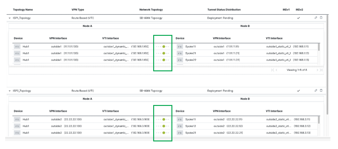
-
To view the auto-generated spoke SVTIs and their IP addresses, click the edit icon next to the topology.

-
Click Edit within the Spokes configuration.

-
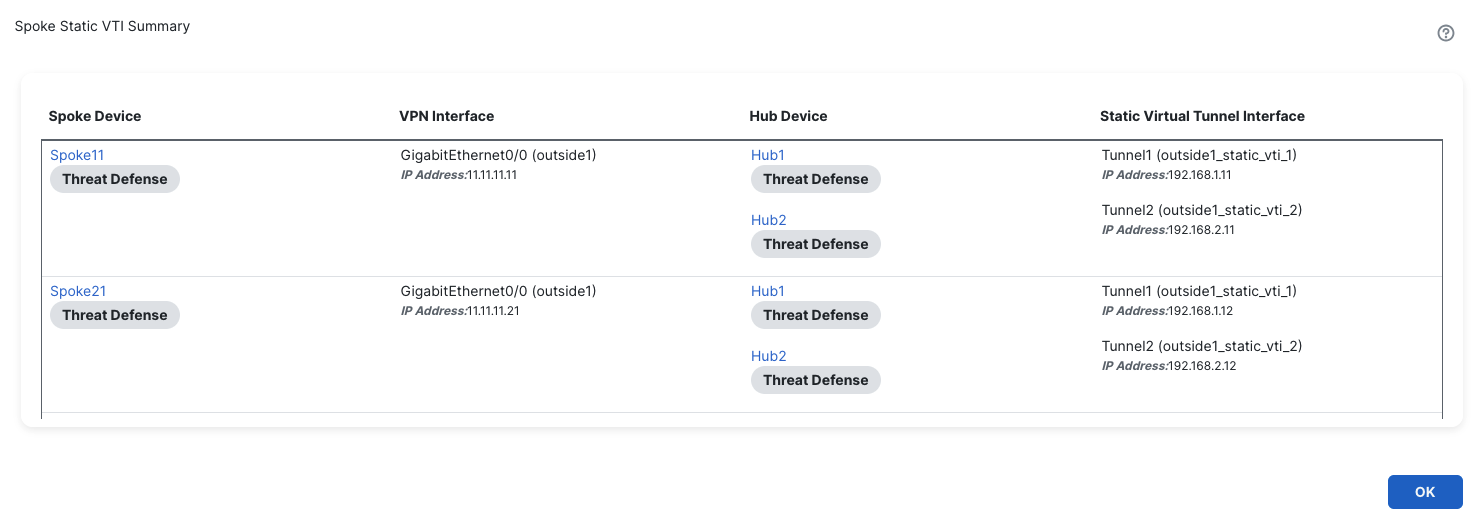
Click View Generated Tunnel Interfaces.

-
This shows all the VTIs generated by the SD-WAN wizard.
-
Alternatively, navigate to Overview > Site to Site VPN Dashboard (or Analysis > Site to Site Monitoring in cdFMC) to see all the active tunnels.

Additional Deployment Scenarios
This section covers some of the common deployment scenarios and the associated SD-WAN Topology configuration guidelines.
Single Hub and Spokes in a Single Region (Single ISP)
In a single hub in a single region, where all the devices are part of a single autonomous system (AS), this wizard enables spoke and hub FTDs to support spoke to spoke routing distribution via Route Reflector support in iBGP deployments.
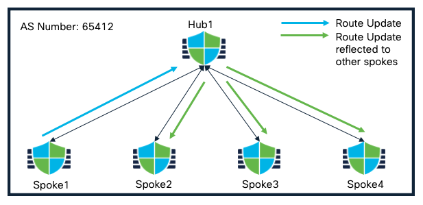
Single Hub in a Single Region(Single ISP) Topology
In this deployment, spokes are configured as route reflector clients while the Hub is configured as a route reflector.
The corresponding SD-WAN Topology consists of the following attributes:
SD-WAN Topology 1
| Primary Hub | Hub1 |
| Secondary Hub | None |
| Spokes | Spoke1, Spoke2, Spoke3, Spoke4 |
| AS Number | 64512 |
| Secondary AS Number | None |
| Number of Tunnels | 4 |
Single Hub and Spokes in a Single Region (Dual ISP)
This scenario is similar to scenario 1 except all the hub and spoke devices have dual ISP connectivity.
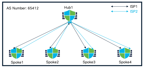
Single Hub and Spokes in a Single Region (Dual ISP) Topology
The corresponding SD-WAN Topology consists of the following attributes:
SD-WAN Topology 1
| Primary Hub | Hub1 |
| Secondary Hub | None |
| Spokes | Spoke1, Spoke2, Spoke3, Spoke4 |
| AS Number | 64512 |
| Secondary AS Number | None |
| Spoke Tunnel Source | ISP1 |
| Number of Tunnels | 4 |
SD-WAN Topology 2
| Primary Hub | Hub1 |
| Secondary Hub | None |
| Spokes | Spoke1, Spoke2, Spoke3, Spoke4 |
| AS Number | 64512 |
| Secondary AS Number | None |
| Spoke Tunnel Sourc | ISP2 |
| Number of Tunnels | 4 |
Dual Hub and Spokes in a Single Region (Single ISP)
In dual hub in a single region, where all the devices are part of a single (AS), both the hubs can be configured as route-reflectors and active/backup tunnels on the spokes are chosen based on the best path.
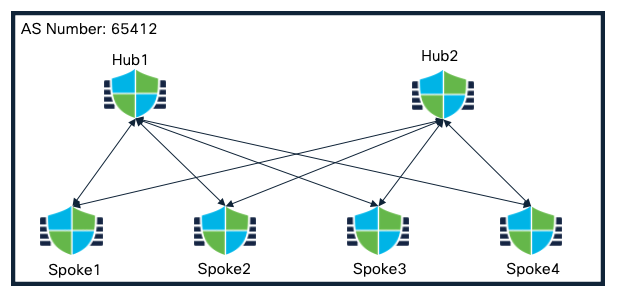
Dual Hub and Spokes in a Single Region Topology
The corresponding SD-WAN Topology consists of the following attributes:
Topology 1
| Primary Hub | Hub1 |
| Secondary Hub | Hub2 |
| Spokes | Spoke1, Spoke2, Spoke3, Spoke4 |
| AS Number | 64512 |
| Secondary AS Number | None |
| Number of Tunnels | 8 |
Dual Hub and Spokes in a Single Region (Dual ISP)
This scenario is similar to scenario 3 except all the hub and spoke devices have dual ISP connectivity.
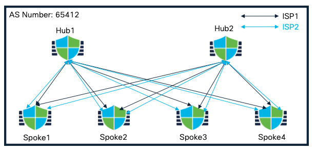
Dual Hub and Spokes in a Single Region (Dual ISP) Topology
The corresponding SD-WAN Topology consists of the following attributes:
Topology 1
| Primary Hub | Hub1 |
| Secondary Hub | Hub2 |
| Spokes | Spoke1, Spoke2, Spoke3, Spoke4 |
| AS Number | 64512 |
| Secondary AS Number | None |
| Spoke Tunnel Source | ISP1 |
| Number of Tunnels | 8 |
Topology 2
| Primary Hub | Hub2 |
| Secondary Hub | Hub1 |
| Spokes | Spoke1, Spoke2, Spoke3, Spoke4 |
| AS Number | 64512 |
| Secondary AS Number | None |
| Spoke Tunnel Source | ISP2 |
| Number of Tunnels | 8 |
Dual Hub in Different Regions with Spokes (Single ISP)
In this design, both the hubs are configured in different AS. These hubs can be configured as route reflector for the spoke devices. Active/backup tunnels on the spokes are chosen based on the best path.
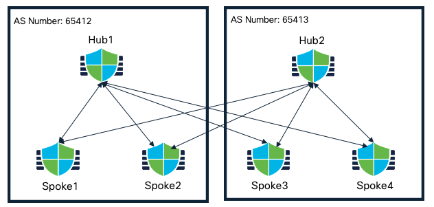
Dual Hub in Different Regions with Spokes (Single ISP) Topology
The corresponding SD-WAN Topology consists of the following attributes:
SD-WAN Topology 1
| Primary Hub | Hub1 |
| Secondary Hub | Hub2 |
| Spokes | Spoke1, Spoke2 |
| AS Number | 64512 |
| Secondary AS Number | 64513 |
| Number of Tunnels | 4 |
SD-WAN Topology 2
| Primary Hub | Hub2 |
| Secondary Hub | Hub1 |
| Spokes | Spoke3, Spoke4 |
| AS Number | 64513 |
| Secondary AS Number | 64512 |
| Number of Tunnels | 4 |
Extended Dual Hub in Different Regions with Spokes (Dual ISP)
Extending the previous design to allow communication between both the hubs, an eBGP peering can be established. In this case, active/backup tunnels on the spokes are chosen based on the best path.
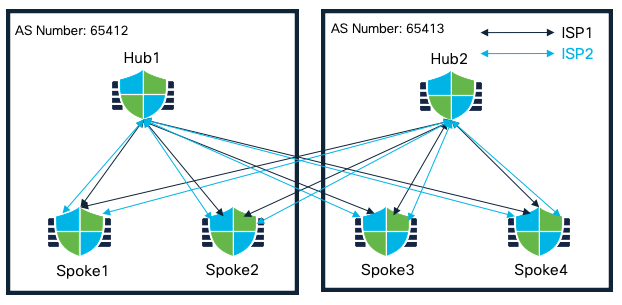
Extended Dual Hub in Different Regions with Spokes (Dual ISP) Topology
Corresponding SD-WAN Topology consists of the following attributes:
SD-WAN Topology 1
| Primary Hub | Hub1 |
| Secondary Hub | Hub2 |
| Spokes | Spoke1, Spoke2 |
| AS Number | 64512 |
| Secondary AS Number | 64513 |
| Spoke Tunnel Source | ISP1 |
| Number of Tunnels | 4 |
SD-WAN Topology 2
| Primary Hub | Hub1 |
| Secondary Hub | Hub2 |
| Spokes | Spoke1, Spoke2 |
| AS Number | 64512 |
| Secondary AS Number | 64513 |
| Spoke Tunnel Source | ISP2 |
| Number of Tunnels | 4 |
SD-WAN Topology 3
| Primary Hub | Hub2 |
| Secondary Hub | Hub1 |
| Spokes | Spoke3, Spoke4 |
| AS Number | 64513 |
| Secondary AS Number | 64512 |
| Spoke Tunnel Source | ISP1 |
| Number of Tunnels | 4 |
SD-WAN Topology 4
| Primary Hub | Hub2 |
| Secondary Hub | Hub1 |
| Spokes | Spoke3, Spoke4 |
| AS Number | 64513 |
| Secondary AS Number | 64512 |
| Spoke Tunnel Source | ISP2 |
| Number of Tunnels | 4 |
Note
Tunnel configuration between both the hubs requires a manual point to point VPN tunnel leveraging any routing protocol as an overlay routing mechanism.
Troubleshooting
Troubleshooting the topology and associated VPN tunnels is similar to the existing troubleshooting methods.
For more details, please refer to the following link: VTI Troubleshooting
Key Callouts
- Only IKEv2 is supported and selected by default.
- Supports only FTD devices as Hub and Spokes.
- IP Pool on each Hub should be unique.
Additional Resources
To learn more about SD-WAN Wizard, please refer to the following link:
Updated 7 months ago
