Device Templates
Introduction
Building up SD-WAN features on Cisco Secure Firewall, release 7.6 brings in the Device Templates feature.
This is a policy and configuration bundle that leverages parametrized configuration and enables administrators with:
- Scalable remote branch rollout
- Pre-provisioning Day 0 configuration to the branch devices
- Similar user experience as a standard device on-boarding/registration on Firewall Management Center (FMC).
NOTE
- This feature is supported with Secure Firewall Management Center running release 7.6, and Secure Firewall Threat Defense devices running 7.4.1 and above.
- Supported platforms are 1000, 1200 Compact, 2100 (on 7.4.1 only) and 3100 series.
- No additional licenses are require to create and configure device templates. Target devices where the templates will be applied must have license entitlement for their respective features.
Overview
Using this feature, branch devices can be fully configured during the on-boarding with all the required configuration, allowing seamless and secure connectivity to resources on the internet or behind other SD-WAN enabled hub and branch sites.
Device templates allow pre-provisioning of the following attributes:
- Interface configuration, including inline sets - for device initialization
- Access Control Policy - for security policies
- Static and dynamic routing - for LAN and WAN connectivity
- Policy Based Routing - for Direct Internet Access (DIA)
- DHCP Server, Relay and DDNS configuration - for LAN users' connectivity
- VPN Topology - for VPN access to Hub and other branch sites
This allows unified configuration deployment on multiple devices at same time.
How it works
At a high level, this feature comprises four steps:
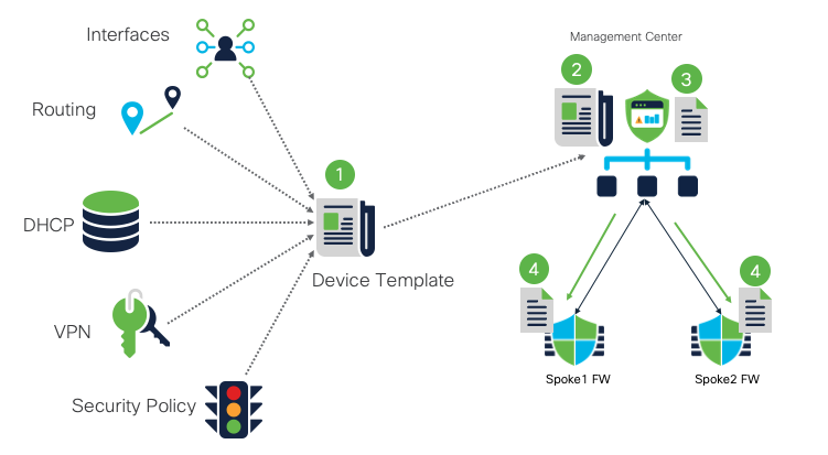
Device Template High Level Overview
- FMC Administrator collates all the device configuration related to interfaces, inline sets, routing, DHCP, VPN and security policies in a unified schema called device template.
- Once configured, device template is then stored on the FMC.
- Management Center creates a copy of the configuration from the device template.
- Copy of the device template configuration is pushed to branch devices called target devices. This template is version agnostic and any feature not supported on the target device is safely dropped from the configuration and logged in the report.
Note
Creating a copy of the template and pushing it to the devices via template ensures that any change in template on the FMC doesn't cause any interruption in the branch device operation.
Device Onboarding Components
Before reviewing the template workflow and configuration, this section covers the components added within template configuration. To assign values to configuration objects in Device Template, there are mainly 2 ways: Variable and Network Object override.
Variable
It is a new object type used as a placeholder for inline values in supported configuration. Admin creates a variable within template creation and variables are replaced with the specific values during the template apply phase.
Fields using the variable have the variable icon and shown with a $ prefix to distinguish from literal values.
Variables support different types of values that are:
- Password
- Rourter ID
- FQDN
- AS Number
- IPv4/IPv6 network addreses
Network Object Override
This is an existing feature which is used within device template. Admin declares an existing network object(s) in the template and override for the object is created or updated during the template apply phase.
Following network object types are supported:
- Network
- Host
- Range
- FQDN
Note
Variables and network object overrides are exclusive in nature. This feature supports variables where network object overrides are not supported.
E.g. variables are used in the interface configuration for IP address assignment whereas network object override is used for defining gateway IP address in the static route configuration.
Template Workflow
Device Template workflow can be logically divided into 3 main steps:
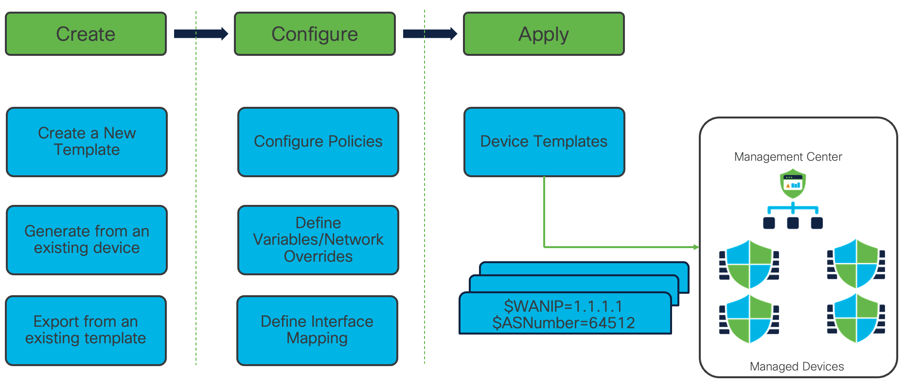
Template Workflow
- Template Creation
This step allows an administrator to configure a reusable configuration template. There are 3 ways to create a template- Create a new template from scratch
- Generate a template from an existing device, and
- Export from an existing template
- Template Configuration
This step covers the actual device configuration that includes Access Control Policy, defining variables and network object overrides, and defining interface mapping. This includes various shared policies and device specific policies. - Template Apply
FMC creates a copy of the configuration from the device template and pushes it to managed FTD devices. In this step, along with the device specific and shared policies, variables and network object override values are configured which are ultimately pushed to the specific branch devices.
Configuration
In this configuration example, we leverage Device Template to onboard a branch FTD device with Dual WAN connections and being managed via the data interface.
The branch device will be configured to have Ethernet1/1 interface as outside1 interface and Ethernet1/3 as outside2 interface. Ethernet1/2 will be used as inside interface. outside1 interface will be used for management via FMC.
Topology
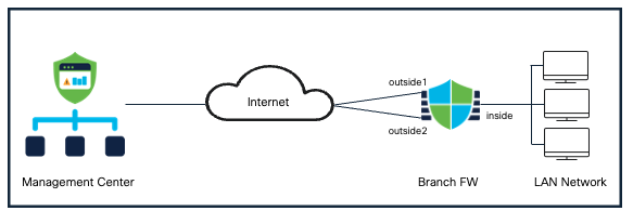
Device Templates Topology
Create a New Device Template
-
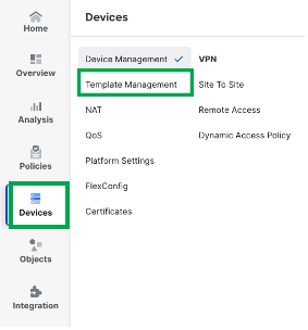
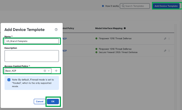
Choose Devices > Template Management
-
Click Add Device Template
-
In the Add Device Template window, enter a Name for the template.
-
Choose an Access Control Policy from the drop-down list.
-
Click Ok
Configure Device Specific Settings
Configuring Interfaces
- Under IPv4, Click + under IP address to create a variable named outside2_interface_ip and click save
- Click Save
- (Optional) Create Inline Sets for the supported branch devices.
Configuring Routing
Configure Template Settings
- Click Add Model Mapping
- Choose the Device Model from the drop-down list.
- Map the template interfaces to the device model interfaces by choosing the interface from the Model Interface drop-down list. Alternatively, click Map Default to map the template interfaces to the device model interfaces based on the slot and port index order.
17 . Click Save. The interface mappings are listed along with the device model and mapping status on the Model Mapping window.
- Click Save on the top right to save the template configuration
Configure Device Registration on Branch Device
- On the FTD CLI, configure the following command to register it to FMC
configure manager add <FMC_Public_IP> <secret_key> <NAT_ID>
e.g. configure manager add 198.18.10.1 cisco1001 cisco1001
Add a Device to the Management Center using a Registration Key and a Device Template
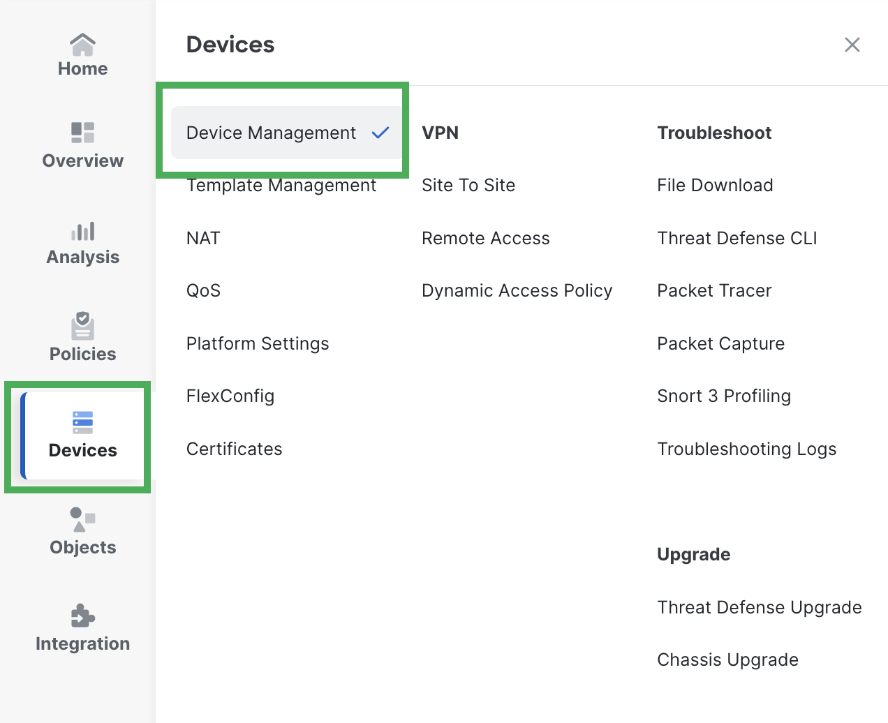
- Choose Devices > Device Management
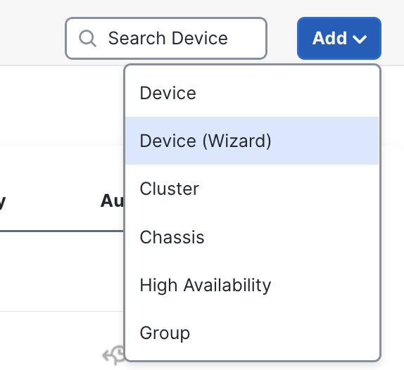
- Click Add > Device (Wizard)
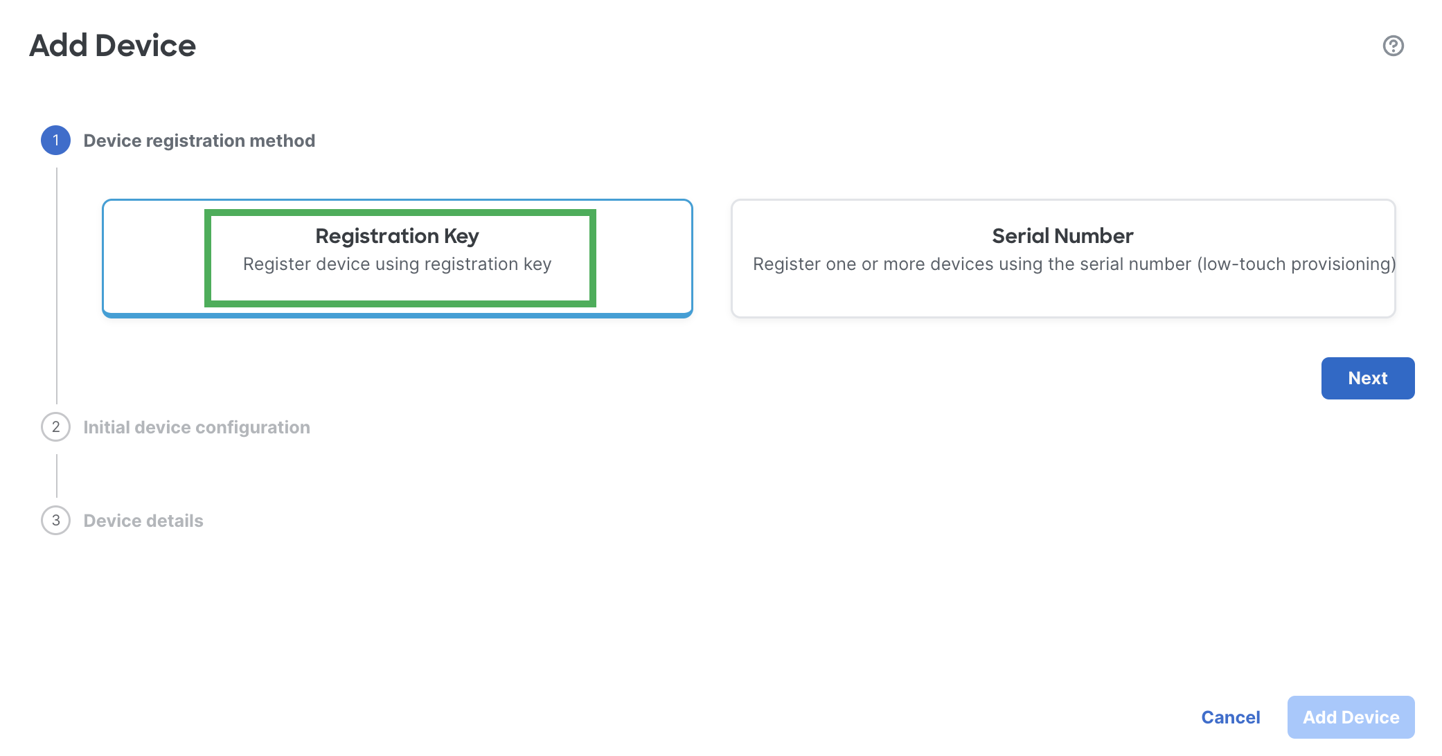
- On the Add Device window, choose Use Registration Key to register a device using a registration key.
- Choose a template from the Device Template drop-down list.
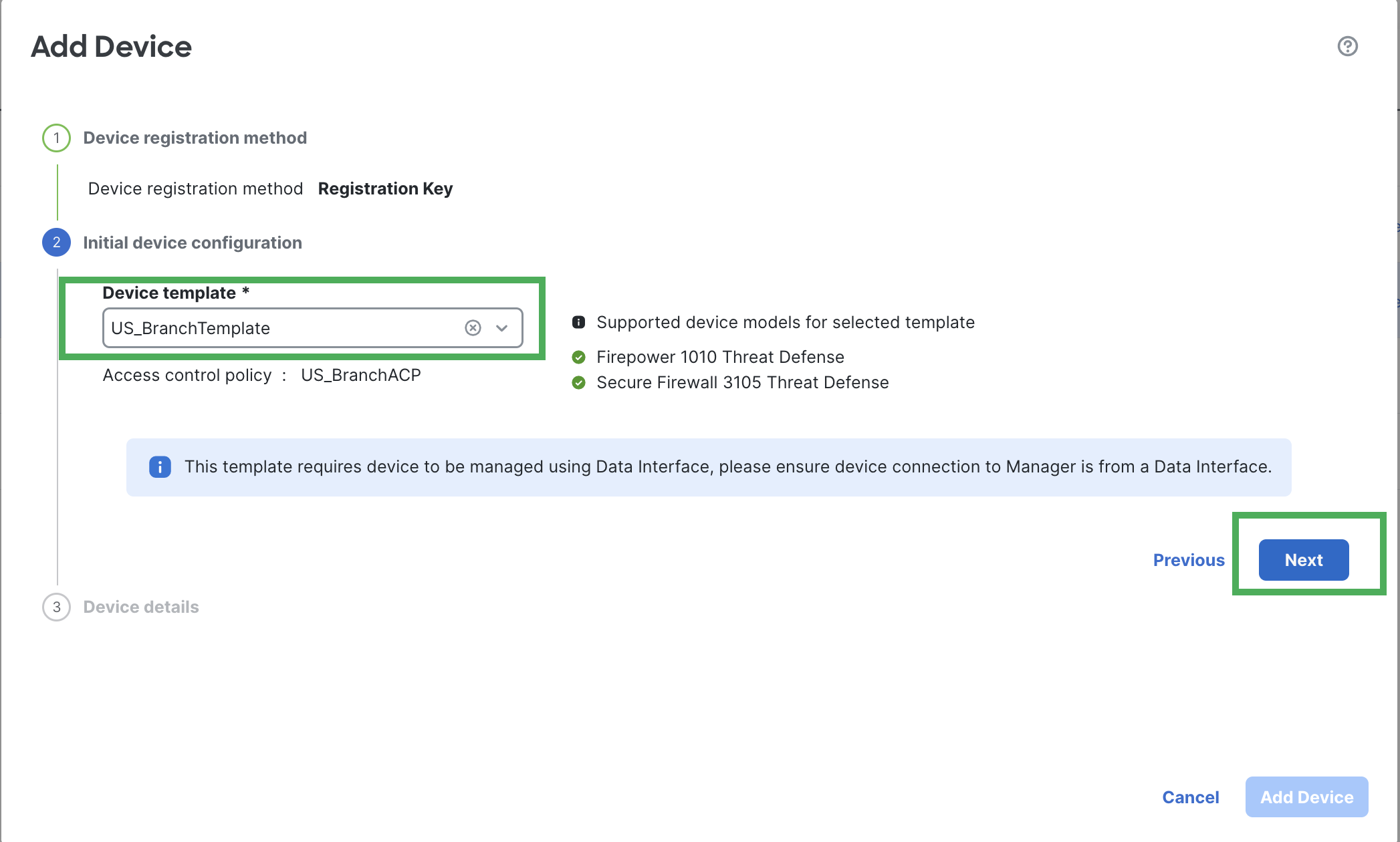
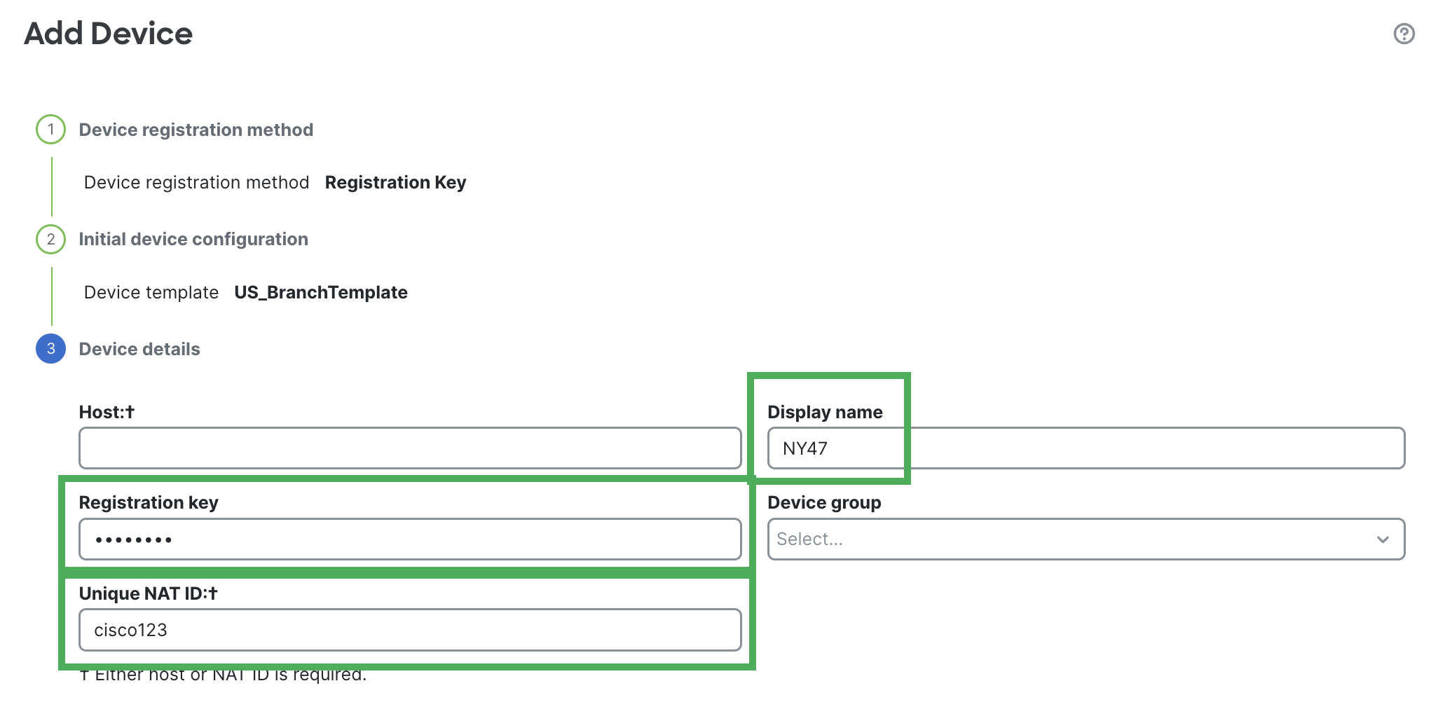
- Under Device Details, configure branch FTD details like Host, Display Name, Registration key, Device Group and Unique NAT ID
Note
You can skip the Host entry if you are using NAT ID for device registration.
- Enter values for the Variables and Network object overrides.
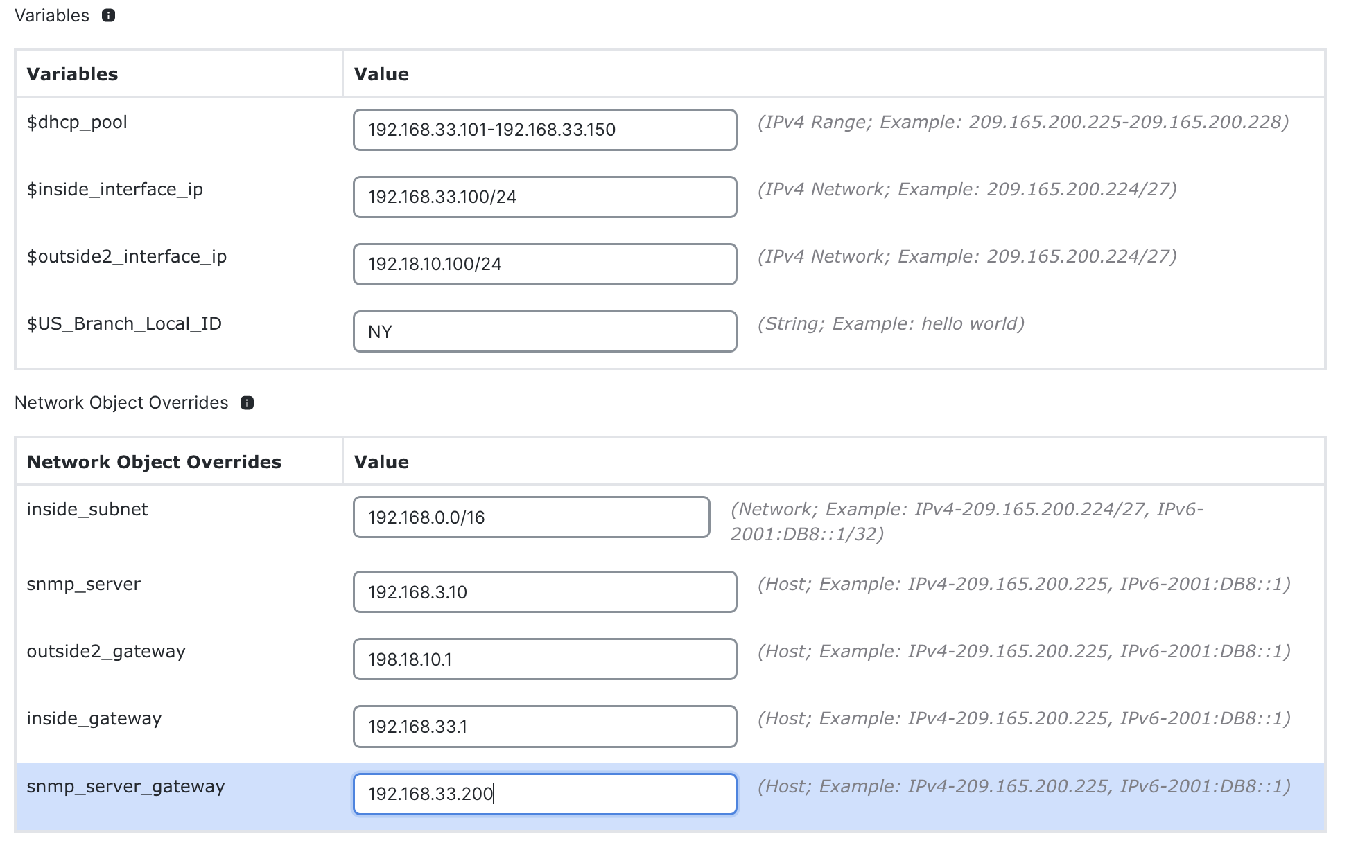
-
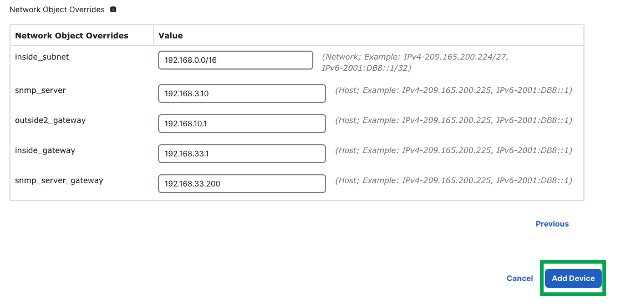
Click Add Device to initiate device registration. The template configurations are applied after the device is successfully registered with the Management Center.
-
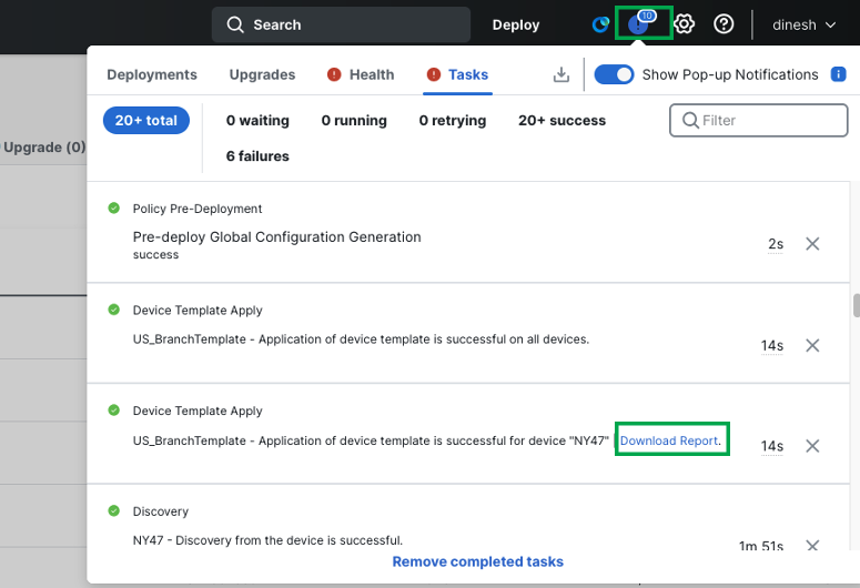
Navigate to Task Notifications and ensure the device template apply is successful.
-
(Optional) Click on Download Report in the task notification to review the details of device template configuration pushed to the branch device.
Note
Device Templates can be used along with SN as well to onboard branch devices.
Verification
To ensure the branch device has the required configuration from the device template, follow the below steps
-
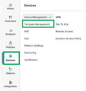
Navigate to Devices > Device Template
-
Edit the Branch Template
-
Click Associated Devices on the far right

-
Ensure the branch device is present in the table and the Sync Status and Apply Status are set to In Sync and Successfully applied the template.

-
If any additional changes are made to the device or the template, click Reapply Template to reapply the template to make the configuration in sync with the template.

Note
If there is any configuration change on device or in the template after template was applied, the template association shows out of sync.
For more details, please refer to the link <https://www.cisco.com/c/en/us/td/docs/security/secure-firewall/management-center/device-config/760/management-center-device-config-76/m_device-management-using-templates.html#concept_vwl_gdd_bbc>
Troubleshooting
- Check the error report to know more about the failure.
- Review the values used for variables and check for overlaps or any incompatibilities
- Ensure that model mapping within a device template is valid
For troubleshooting device templates related issues, please refer to the following link: Device Templates Troubleshooting
Key Callouts
- Maximum of 250 device templates supported on the Management Center
- Management and diagnostic interfaces must be converged
- Not supported with multi-instance or cluster deployments
- No override support for network groups and other object types
- Templates can be applied on HA devices. However, application of device templates during HA device pair registration is not supported.
Additional Resources
To learn more about device-templates, please refer to the following link:
Updated 7 months ago
