AWS Dual-Arm GWLB Support
Introduction
A Gateway Load Balancer (GWLB) is a common solution for managing multiple virtual appliances in a public cloud like AWS. While deploying Cisco Secure Threat Defense Virtual on AWS you can use GWLB to distribute load across numerous firewall instances to secure your North/South and East/West traffic flow.
In this guide, we will look at how you can configure the firewall on AWS with GWLB using the new “Dual Arm” feature available on the new Cisco Secure Threat Defense Virtual 7.6.
Background Information
Cisco Secure Threat Defense Virtual deployed behind AWS GWLB previously only supported single-arm deployment for outbound traffic. AWS GWLB used to send the traffic to the firewall which after inspection was returned to AWS GWLB (U-turn); this inspection path was not optimal as it requires the packet to go through GWLB and GWLB endpoint twice.
In the dual-arm mode, after packet inspection, instead of sending the packet back to GWLB, the Cisco Secure Threat Defense Virtual will simply NAT and forward the traffic to the internet gateway via the outside interface. This reduces the number of traffic hops by 2.
It also provides a common egress path for multi-VPC deployment. Outbound traffic from multiple VPCs exits from a single point to the Internet after inspection by a firewall. Less infrastructure requirement makes this solution cost-effective.
Prerequisites
- A valid AWS account with proper permissions.
- FTDv 7.6.0 and FMC 7.6.0 are the minimum version required to use this feature.
- Valid license. Both Bring Your Own License (BYOL) & Pay As You Go (PAYG) models are supported.
Note: Clustering is not supported with Dual-Arm FTDv
Topology and End-to-End Flow
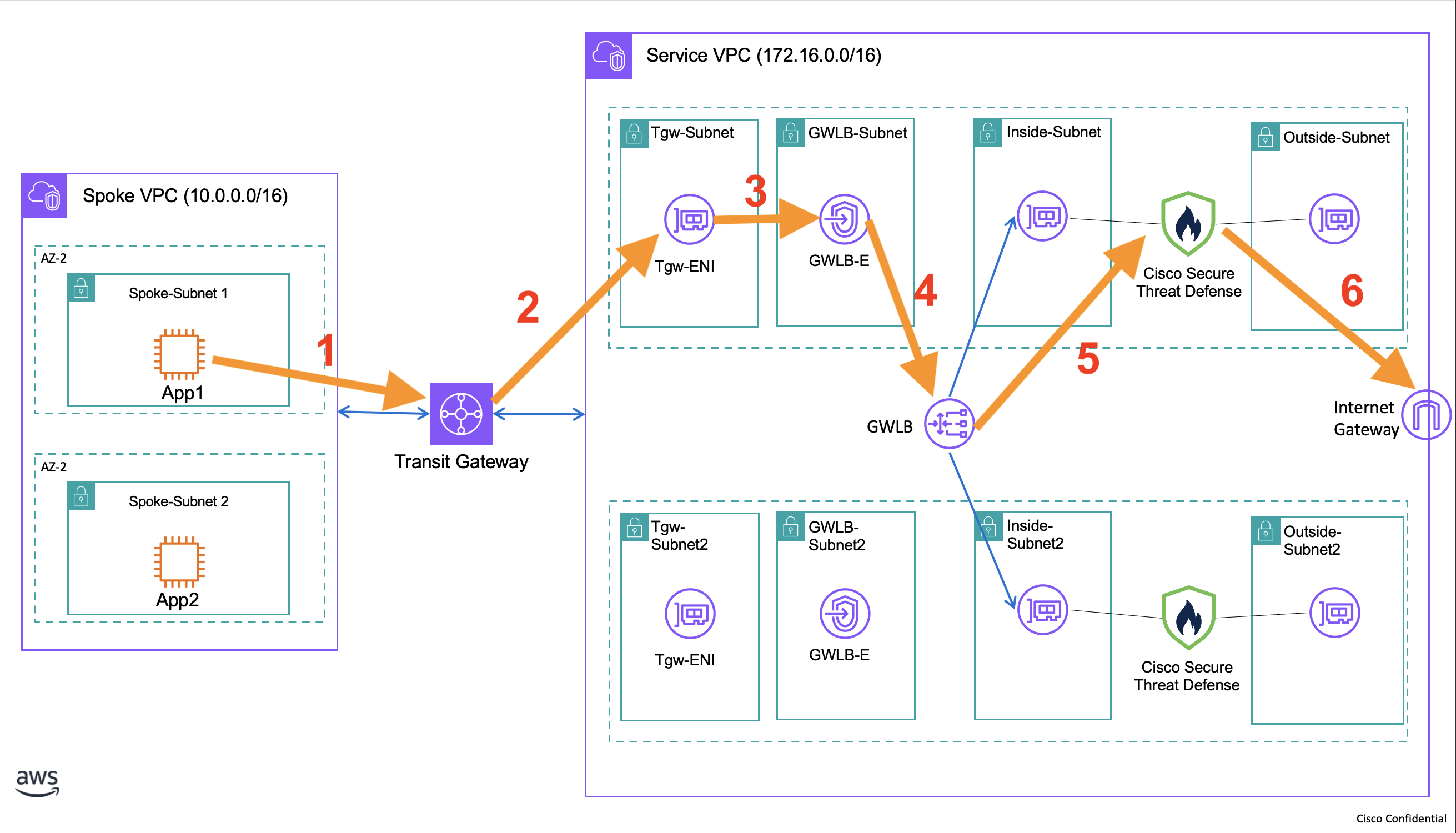
For outbound traffic:
- The outbound traffic from your application reaches the Transit Gateway.
- Transit Gateway will send the packet to the chosen subnet in the intended VPC.
- The packet then will be sent to the Gateway Load Balancer endpoint.
- The endpoint sends the packet to GWLB.
- The GWLB will load balance the data and send it to your Cisco FTDv.
- After inspection, the Firewall will NAT the traffic & send it to the internet gateway via its outside interface.
Configuration
Step 1: Configure Interfaces
Go to Device > Device Management
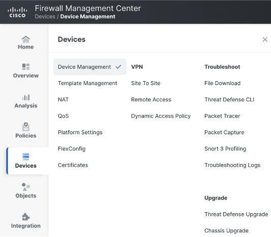
Click on the pencil icon next to the chosen FTD.

Click on the interfaces tab.
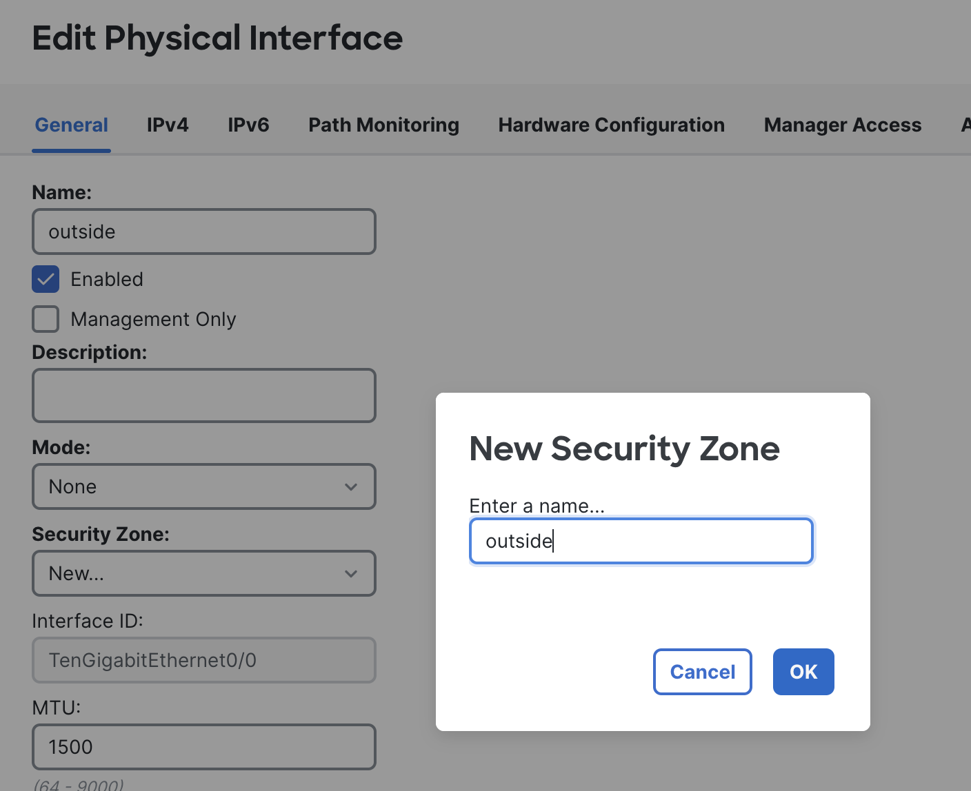
Configure TenGigabitEthernet0/0 by clicking on the pencil icon next to it. This is the outside interface in our topology
NOTE: The interface order will highly depend on the sequence of network interfaces attached while deploying the VM on AWS.
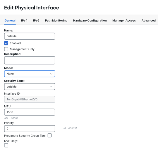
Please provide the name as outside and create a new Security Zone called outside by choosing the New... option from the drop-down menu.
Make sure that the Enabled checkbox is ticked.
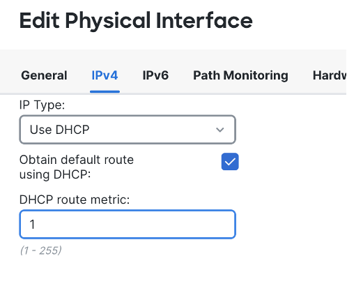
Head to the IPv4 tab and use DHCP in the IP Type to configure the IP address of your interface.
Click on OK.
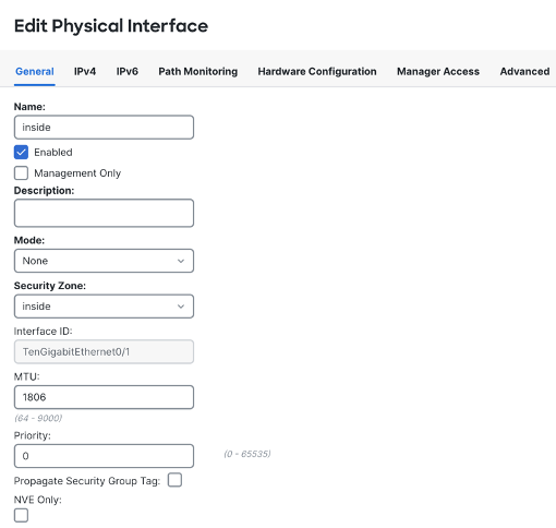
Do the same for TenGigabitEthernet0/1. Configuration would be
Name: inside
Security Zone: inside(create it exactly like above)
IPv4: DHCP.
Click on OK.
Click on SAVE in the top right corner.
This is how your physical interfaces should look like

Step 2: Configure VTEP
Click on the VTEP tab from the top.
Click on the checkbox Enable NVE.

Click on Add.
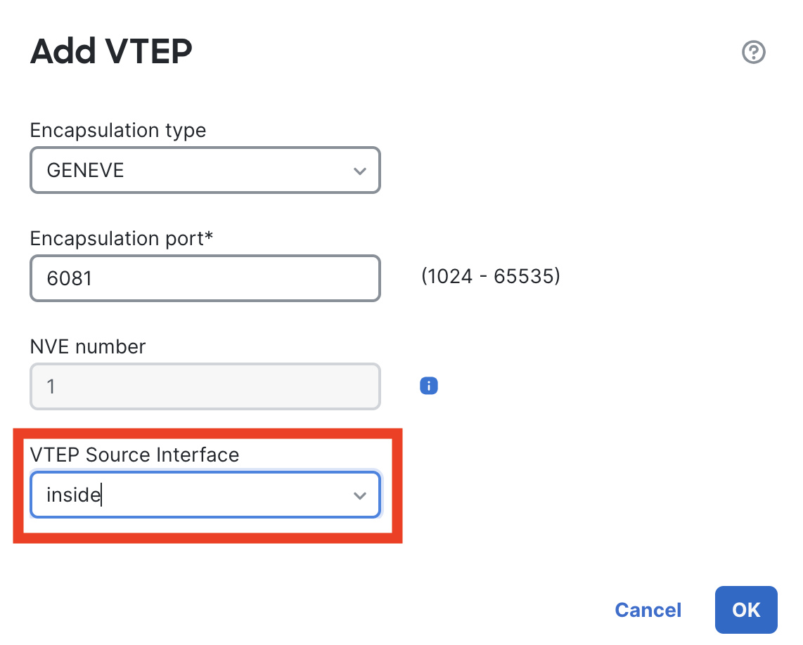
Let all the values be default, select inside as your interface.
Click on SAVE in the top right corner.
Step 3: Configure VNI
Head back to the Interfaces tab.
Click on Add and select Virtual Network Interface.
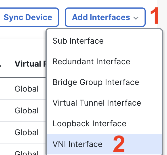
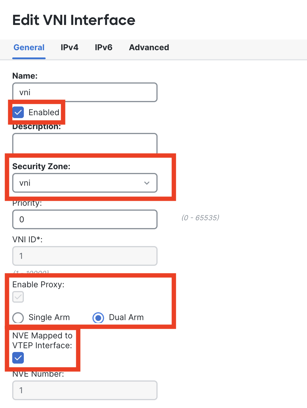
Please provide the name as vni and create a new Security Zone called vni by choosing the New.. option from drop-down menu. For VNI ID pass ‘1’.
Enable proxy and select Dual Arm. Lastly, enable NVE Mapped to the VTEP Interface.
This is how the Final Config should look like.
Click on SAVE in the top right corner.

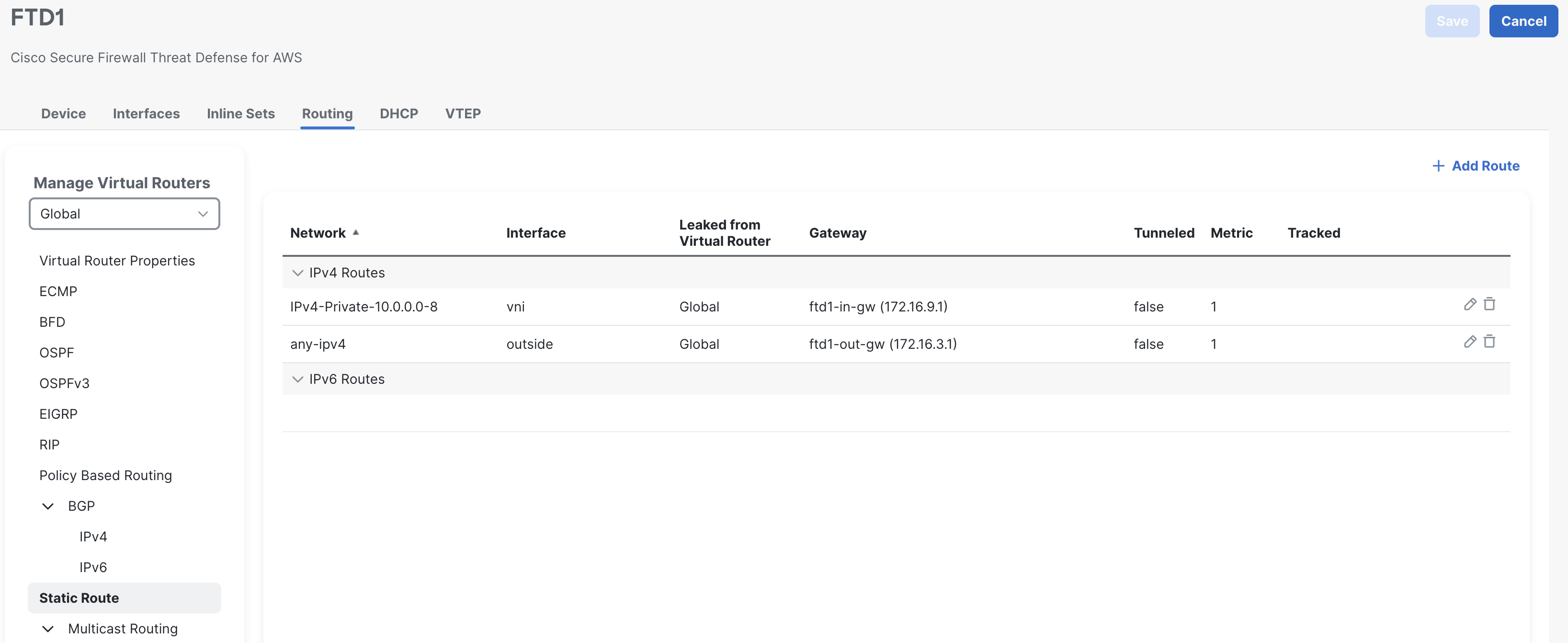
Step 4: Configure Static Routes
Head to the Routing Tab, click on Static Route and then click on Add Route.
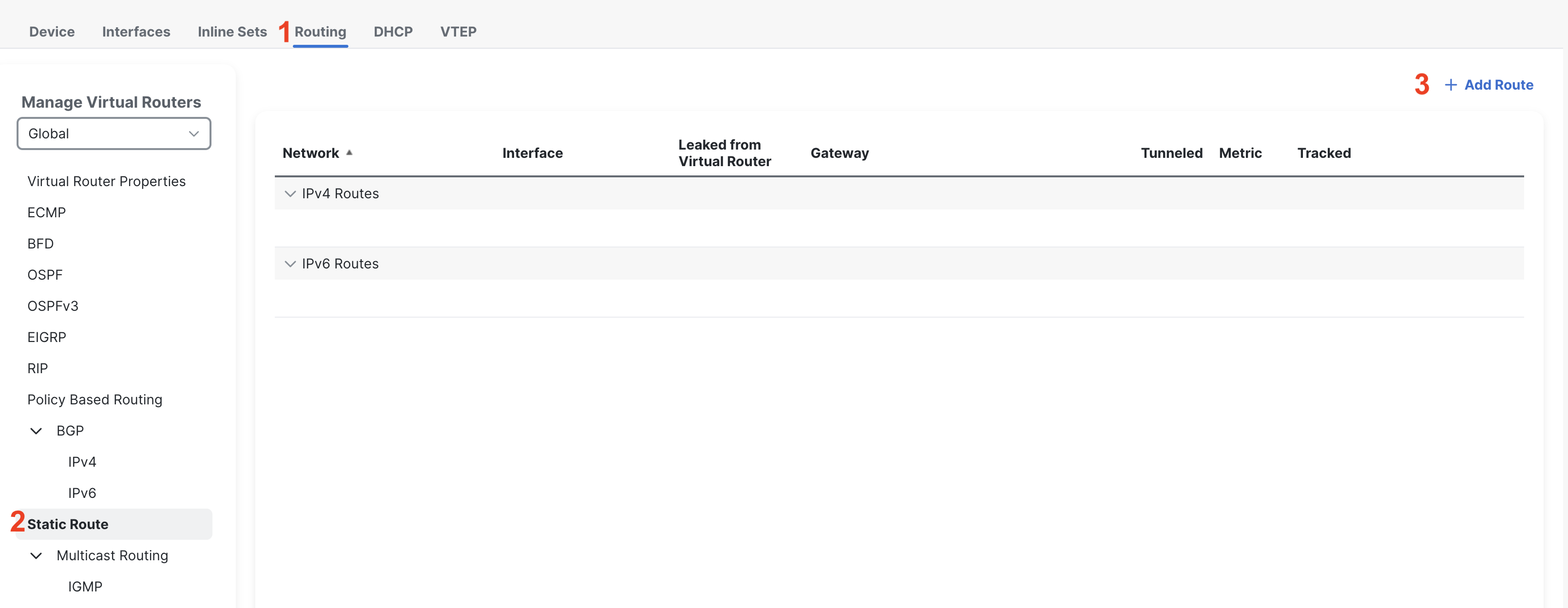
We will first create a route for the outbound traffic to be routed to the Internet Gateway. Select the outside interface and add any-IPv4 from the available network window.
You will have to create a gateway pointing to your subnet's outside gateway. In AWS it will be the first IP address of your subnet.
For example: if the subnet is 172.16.3.0/24 then the gateway will be 172.16.3.1.
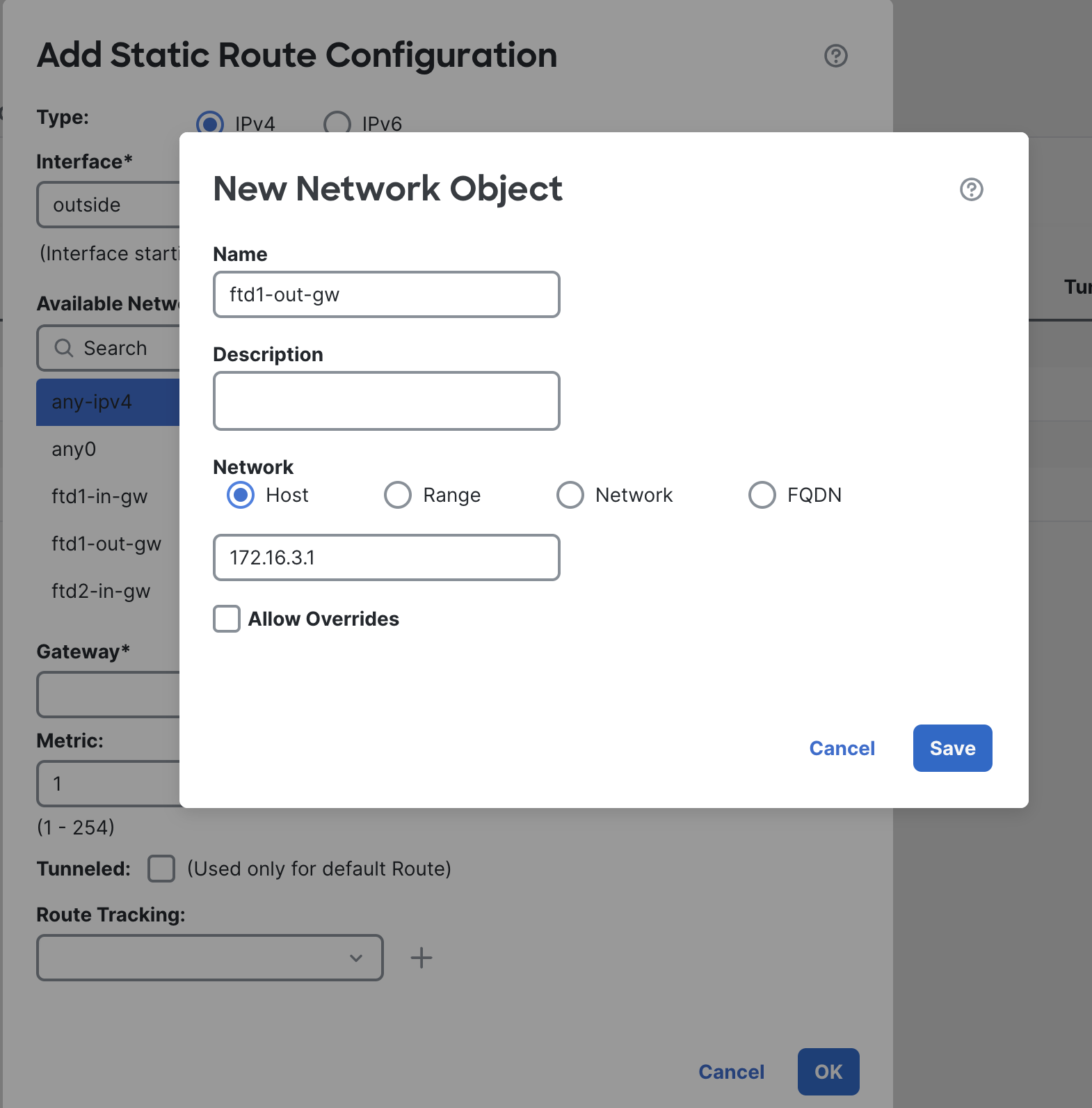
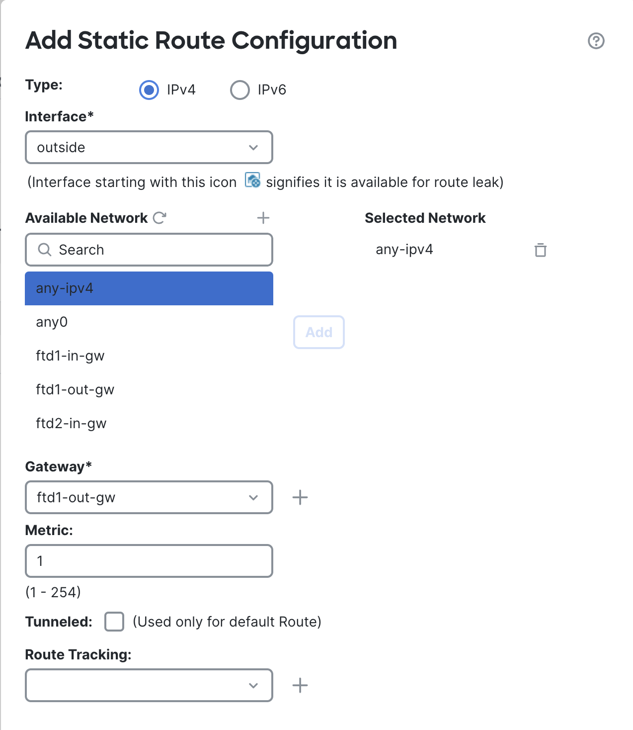
Leave everything else as it is, click on OK.
Optional: create a route for the vni interface, this route will be used for the East/West Traffic.
Click on Add again, select the vni interface and add the network that belongs to your spoke network. For the gateway, create an object by clicking the + icon. Use the inside subnet’s gateway here.
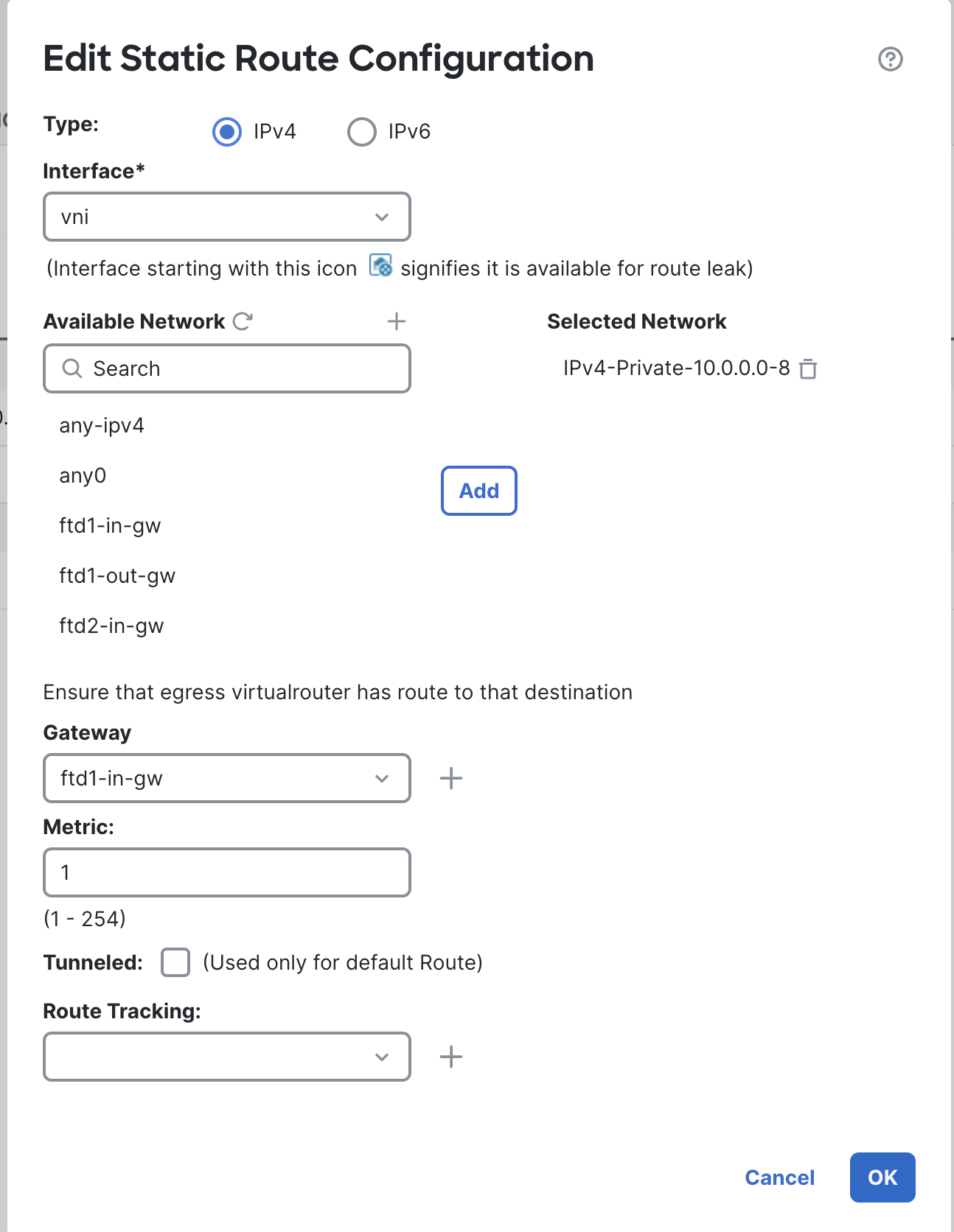
Leave everything else as it is, click on OK.
Click on SAVE in the top right corner.
Step 5: Configure Access Rule
Let’s create an access rule to allow traffic from the inside machine to the Internet.
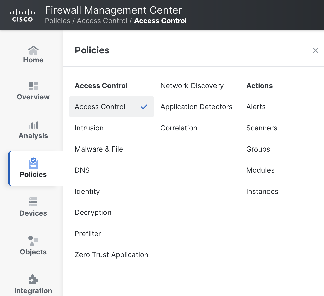
Navigate to Policies > Access Control and then click the pencil icon next to the access policy.
Click on Add.
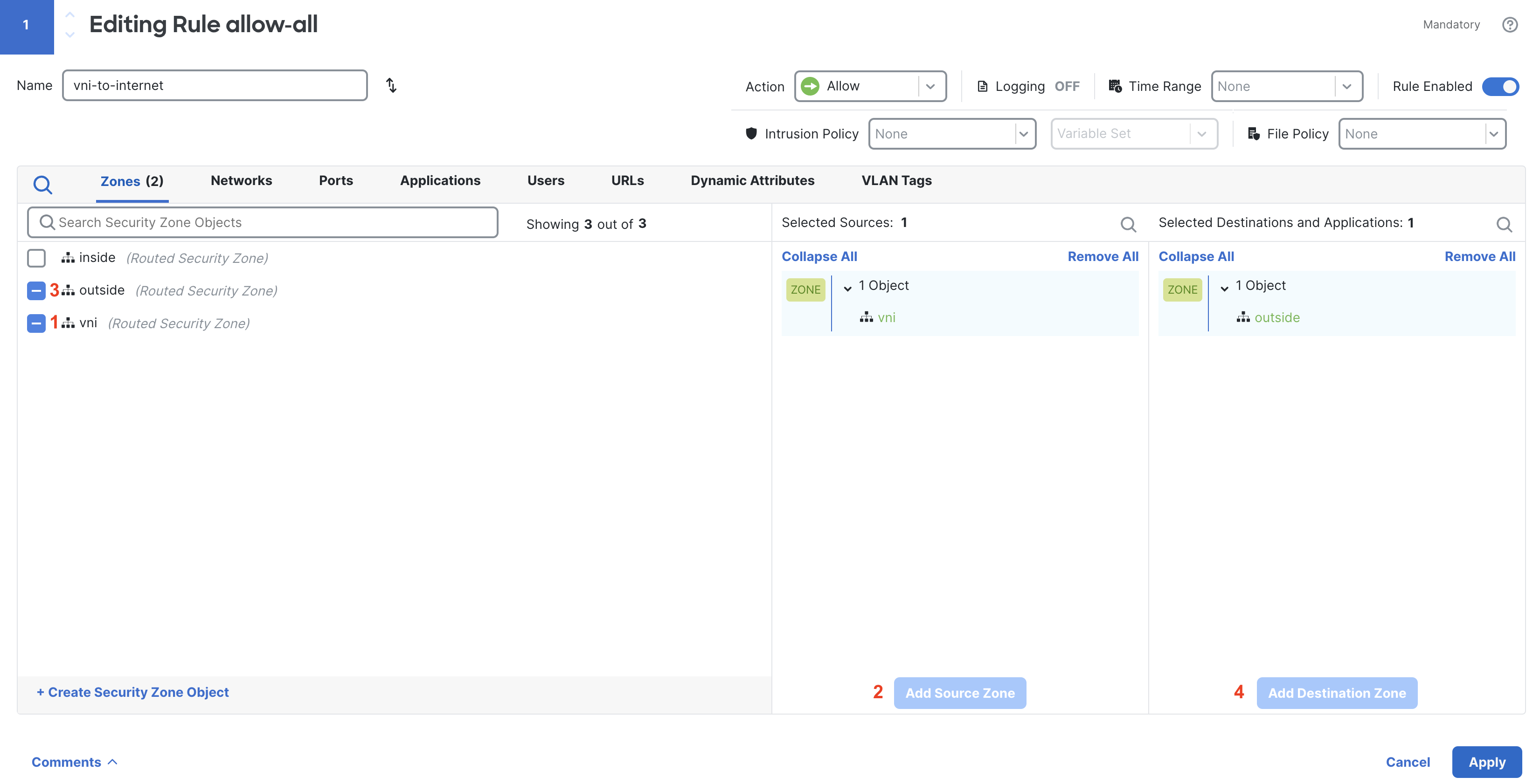
Name it vni-to-internet. For the source zone select vni & for the destination select outside.
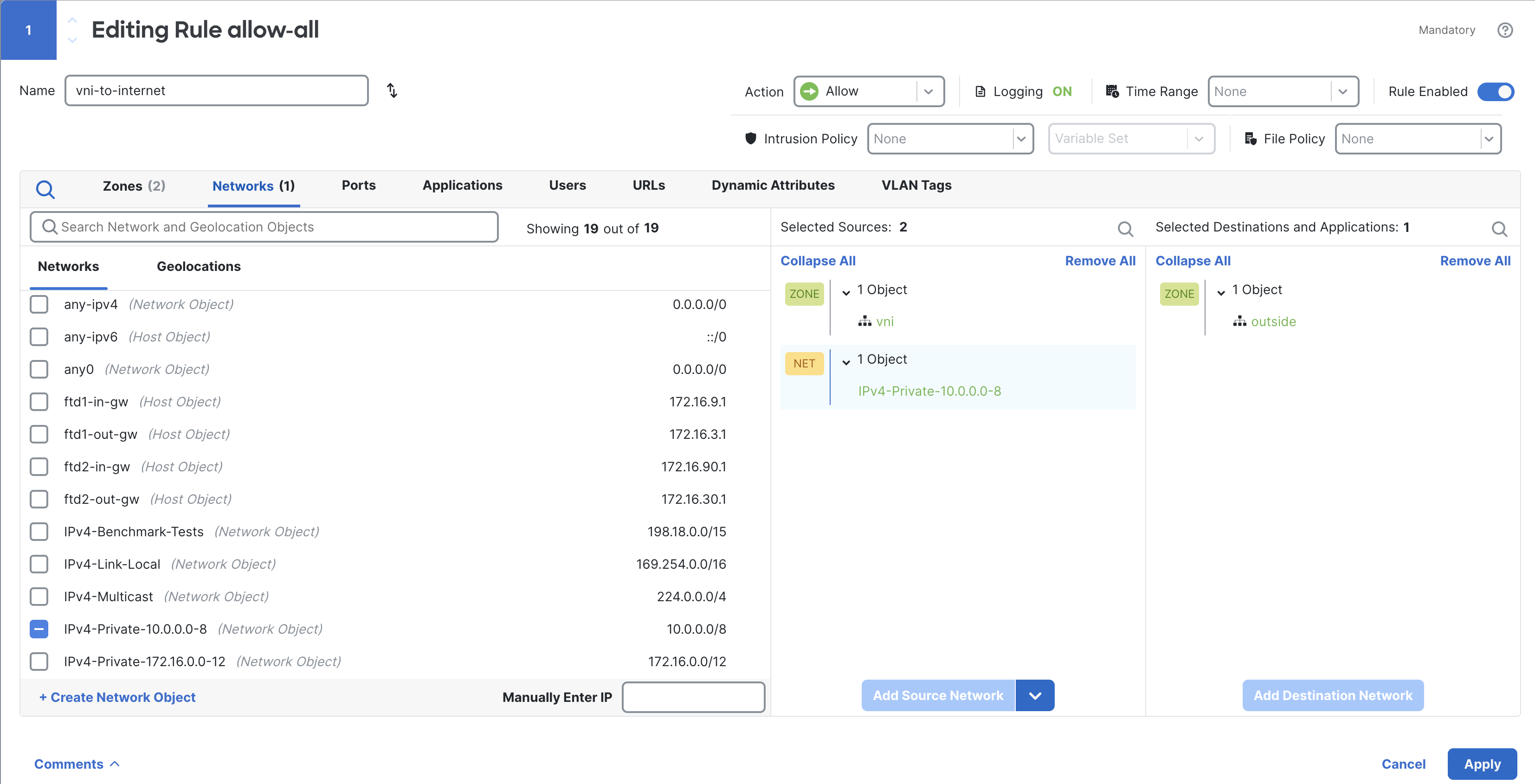
Head to the Networks tab and add the source network where your inside machine is living.
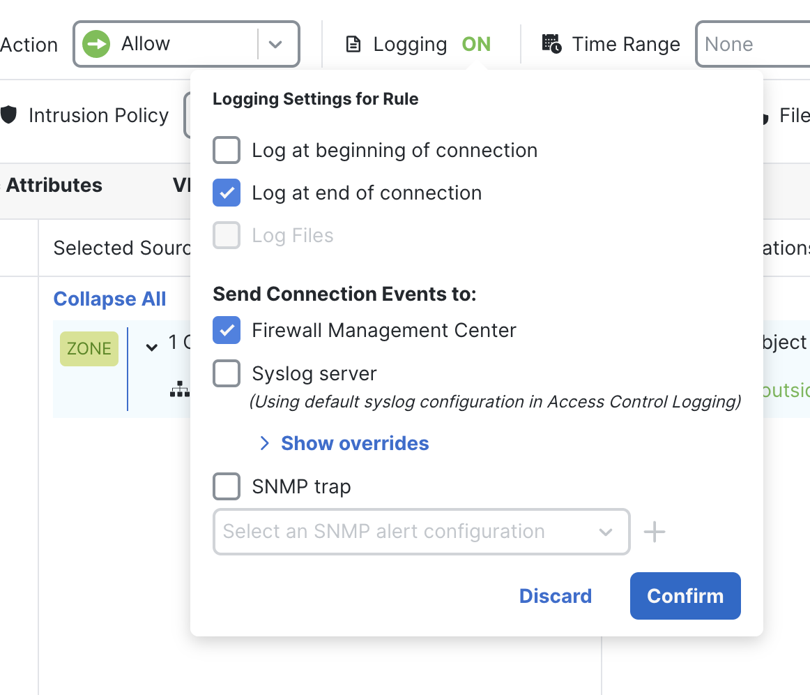
Click on the logging option & select “End of connection.”
Click on Ok & save the rule

Step 6: Configure Nat Rules
Let’s configure one Nat Rule which allows the traffic to reach the internet.
Go to Device > NAT.
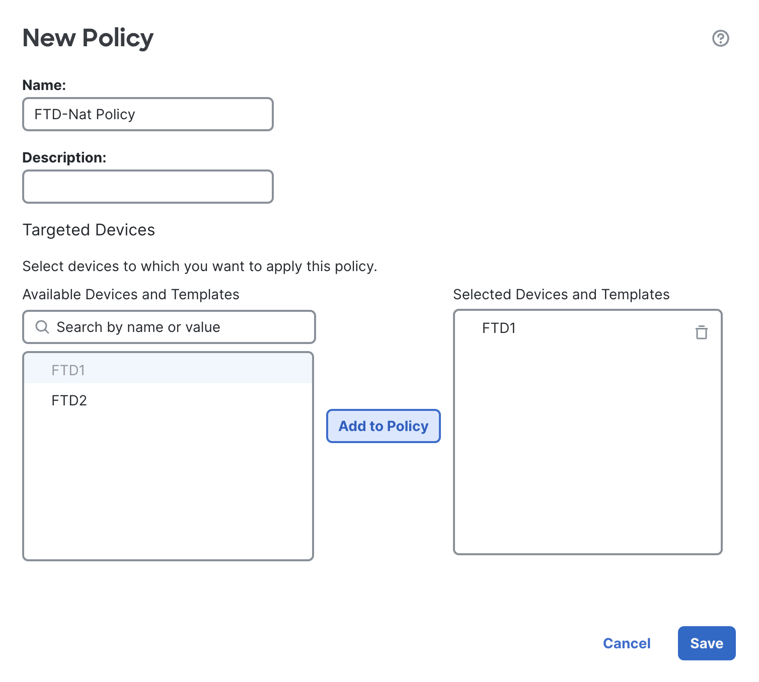
Click on New Policy, name the policy as FTD-Nat Policy and add your device to the policy.
Click on Save.
Once the page opens, click on Add Rule.
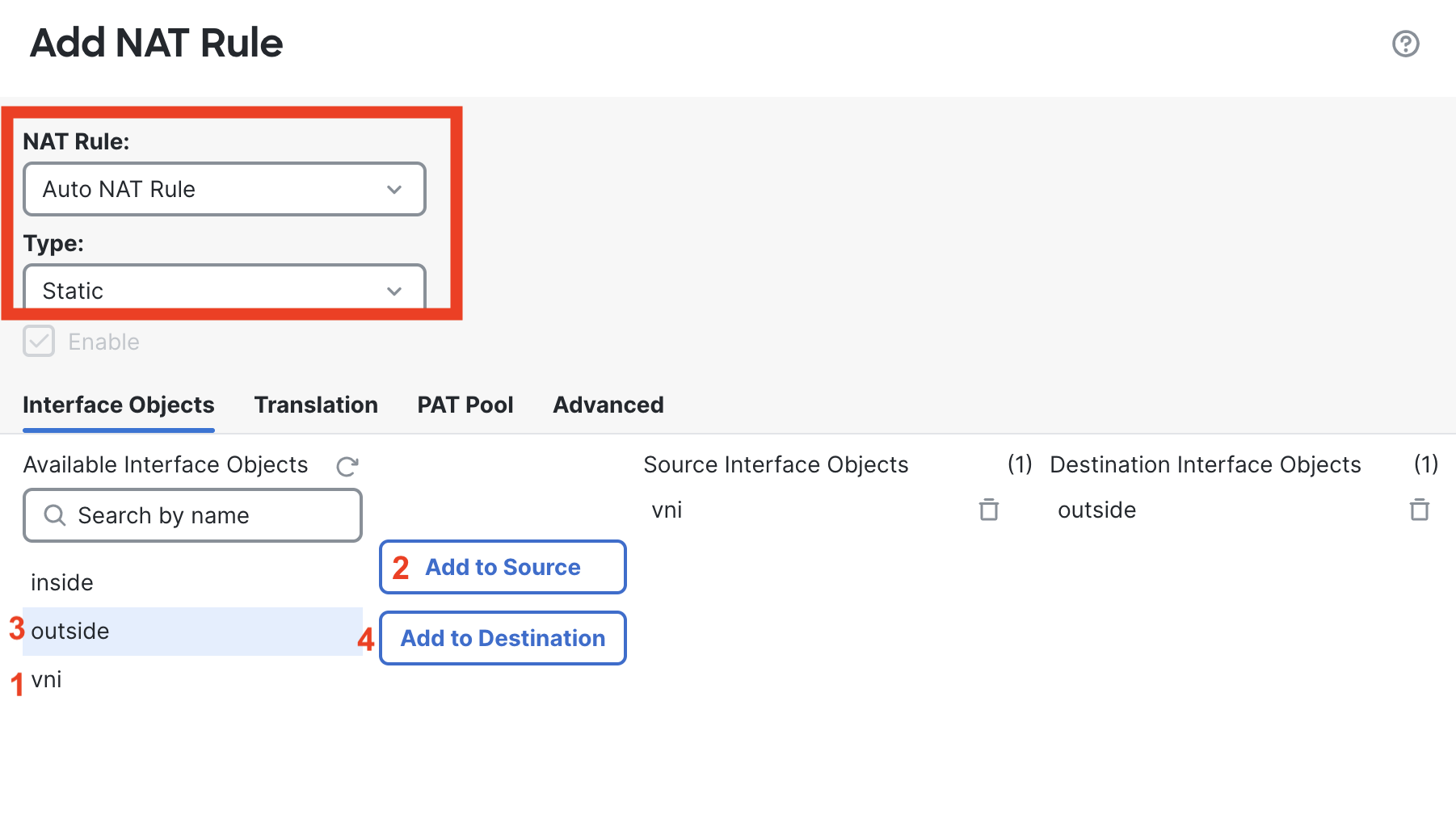
Select Auto NAT Rule from the NAT Rule dropdown menu and leave the type as static. Go to the Interfaces Objects tab, for source interface objects add vni & set outside as destination.
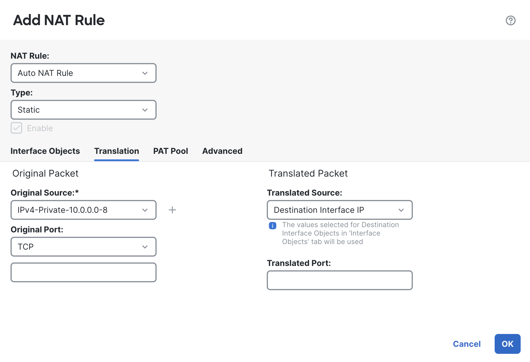
Under the Translation tab, pass the object you created for your application's subnet under original source. For our topology, it’s 10.0.0.0/8.
Under the translated source section, select Destination Interface IP from the drop-down.
Click on Ok and Save the NAT Rule.

Step 7: Configure SSH Access for Inside Interface
We will need to provide SSH Access to the inside interface of the FTD to ensure that GWLB health checks pass. AWS uses TCP Port 22 by default for their health checks.
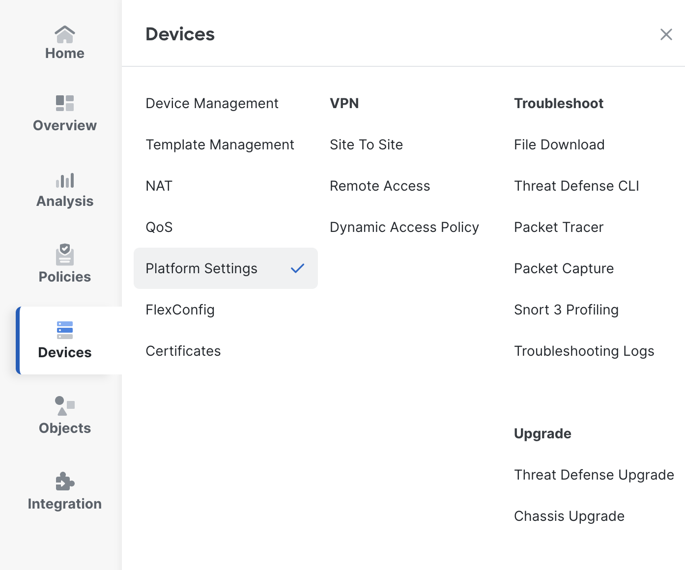
Click on Device > Platform Settings.
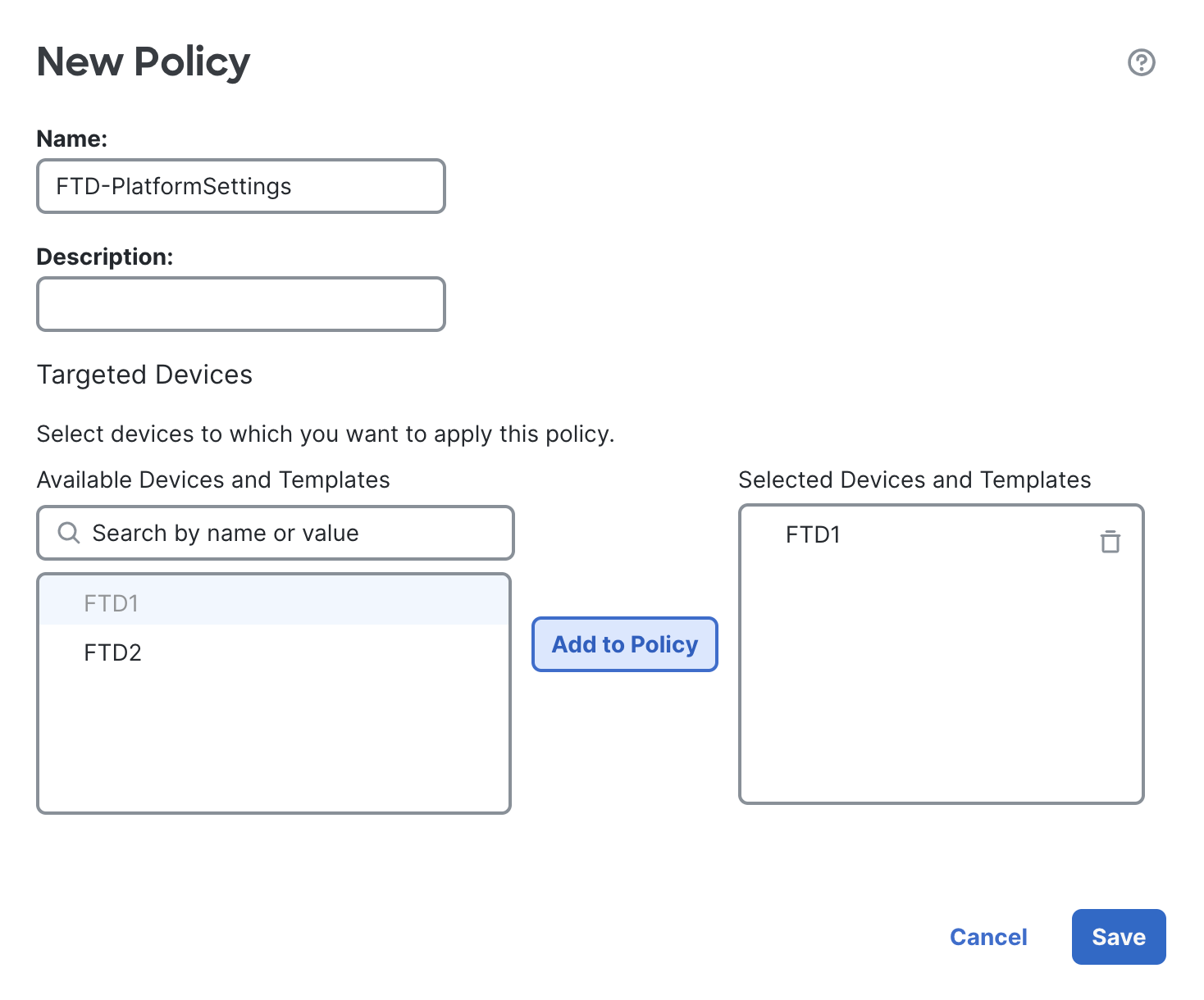
Click on New Policy, select Threat Defense Settings. Add the name FTD-PlatformSettings. Select the desired FTD and add it to the policy.
Edit the policy & go under SSH Access, click on + Add button.
For network select any-IPv4 and choose the inside interface. Click Ok and Save the settings.
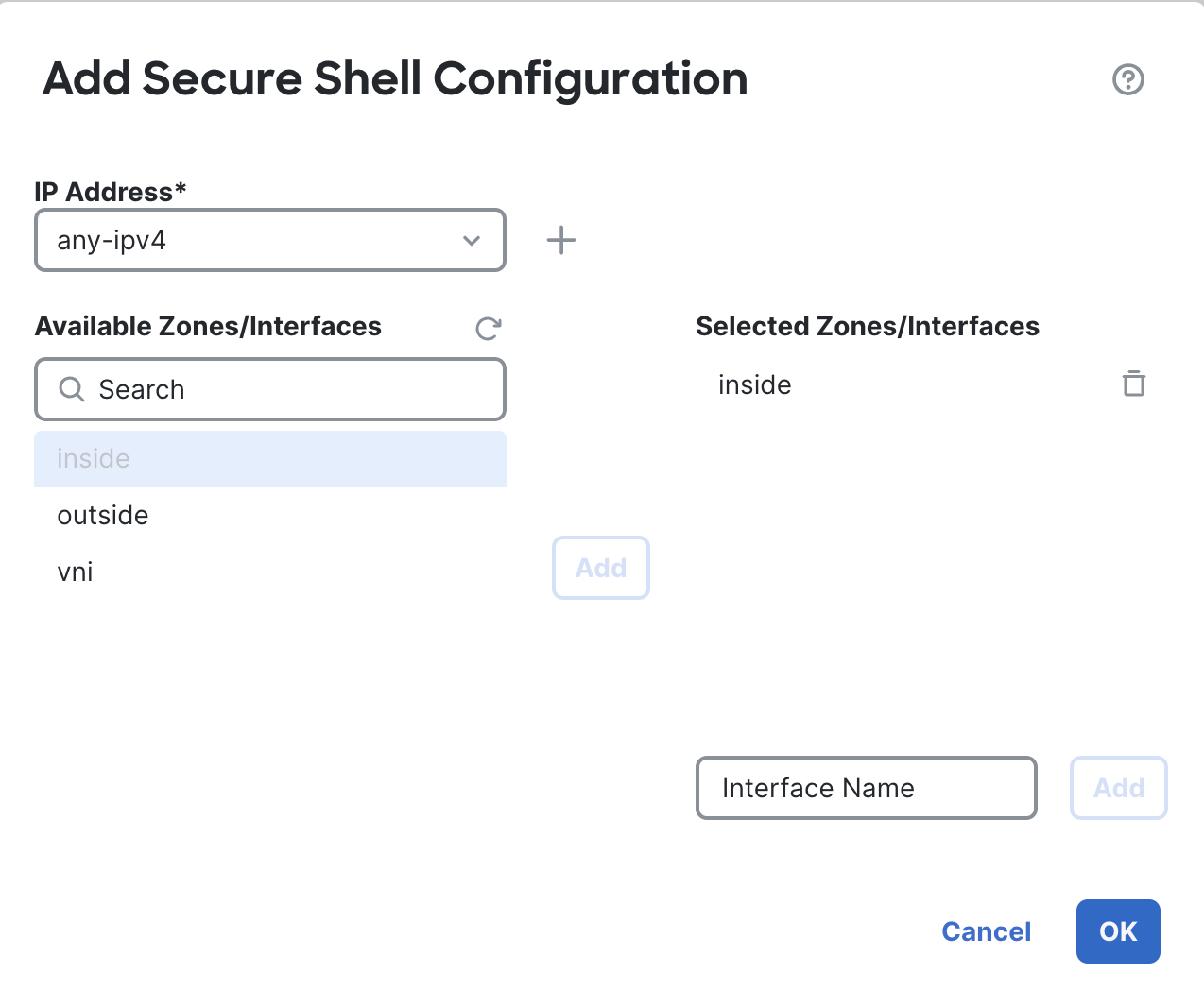
Click on OK and Save it.
Step 8: Deploy
Lastly, we need to deploy all the changes made to the FTD device.
Click on the Deploy button, select the needed device and deploy the changes.
Verification
From your inside machine try to access the internet, the aim is to verify if the packet can reach the internet via the firewall.
ping 8.8.8.8
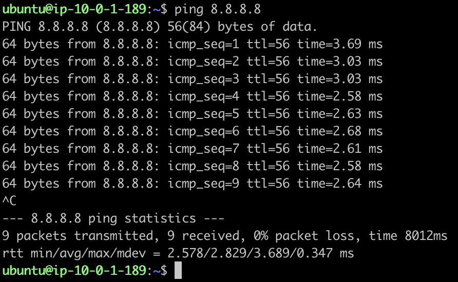
Optionally you can also generate some 443 traffic by curling these websites:
curl https://www.cisco.com
curl https://google.cisco.com
So should be able to see the ping and curl going through successfully. To verify if the packets are indeed going from the firewall, head on to Analysis > Connection> Events.
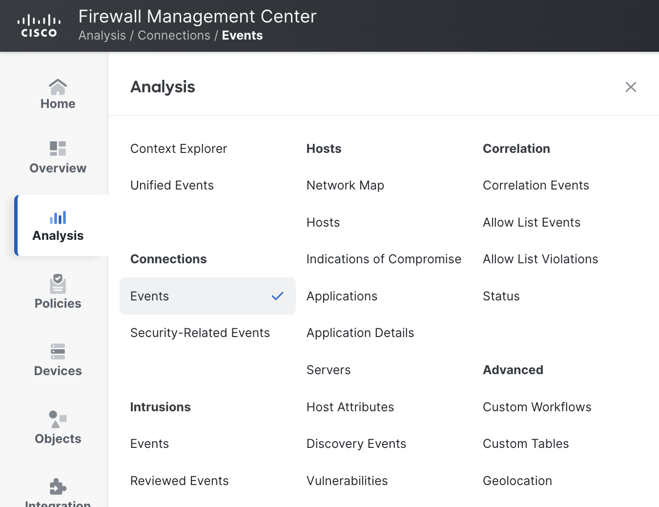
Here you should be able to see the traffic that you just created from your inside machine. If needed, you can also filter events by source IP.

That’s it!! Thanks for reading through the guide.
Updated 8 months ago
