
Virtual Routing and Forwarding
Configuring Virtual Routing and Forwarding (VRF) on Cisco Secure Firewall
Introduction
The Virtual Routing and Forwarding (VRF) feature was added in Firewall Threat Defense (FTD) release 6.6 to allow for routing table segregation. Also, VRF allows network segments with overlapping IP address spaces. VRF implementation on FTD is akin to VRF-lite on Cisco routers. You can also use VRFs for routing plane separation during migration from multi-context ASAs to FTD.
Release 7.2 adds VRF support for the 1010 series and allows VTIs in user-defined VRFs.
Configuration
Using VRF, we can separate the firewall functions for different routing domains across an enterprise network. Also, it allows for overlapping address space to co-exist and communicate through the FTD.
Note
The FMC and FDM user interface refer to a VRF as Virtual Router. These terms will be used interchangeably.
Firewall Management Center
This section details the configuration steps using Firewall Management Center (FMC).
Creating a VRF
Step 1: Choose Devices > Devices Management. Click on the "pencil" icon against the FTD you wish to configure for VRFs.
Step 2: Click on the Routing tab.
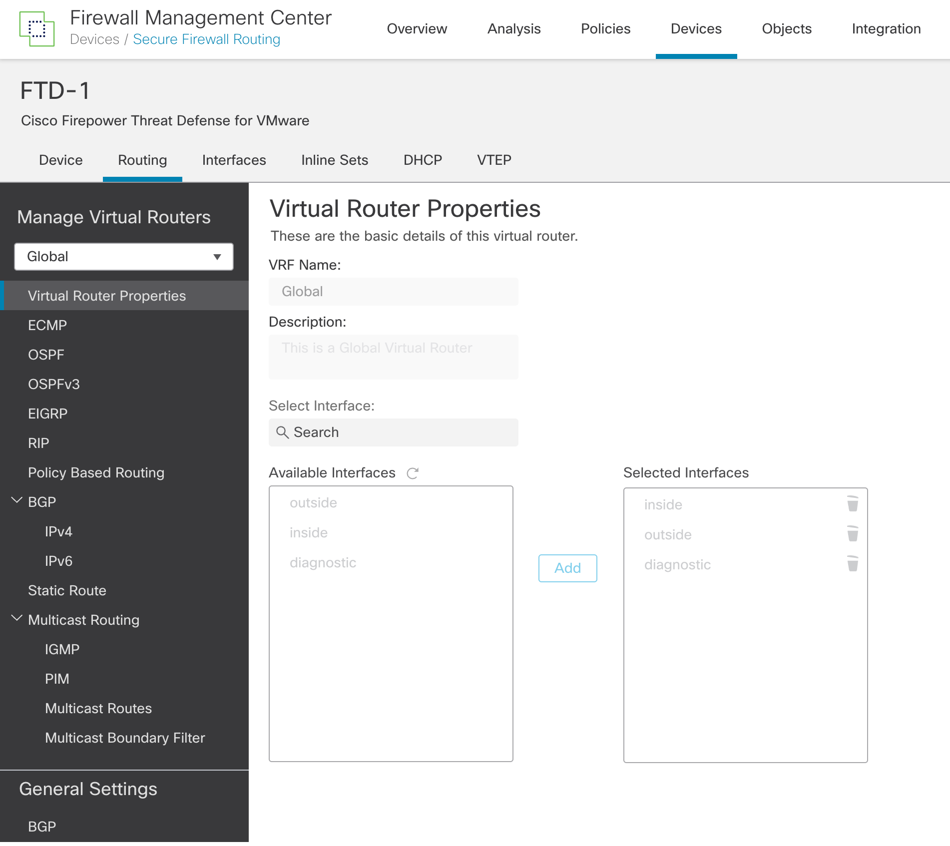
Figure 1: Routing tab
Step 3: Click Manage Virtual Routers. Notice that all the interfaces are assigned to the Global VRF, which is the default configuration.
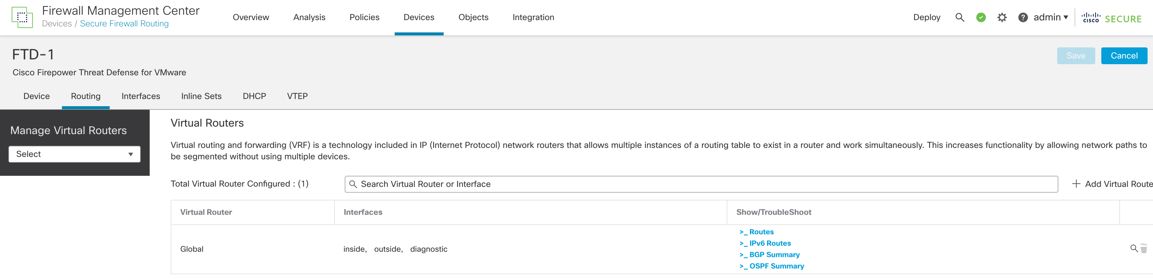
Figure 2: Manage Virtual Routers
Note
Under Manage Virtual Routers, there is a dropdown menu to select a VRF. After creating a new VRF, use this to select that VRF and configure settings within the VRF, such as interface assignments, static and dynamic routing.
Step 4: Click + Add Virtual Router
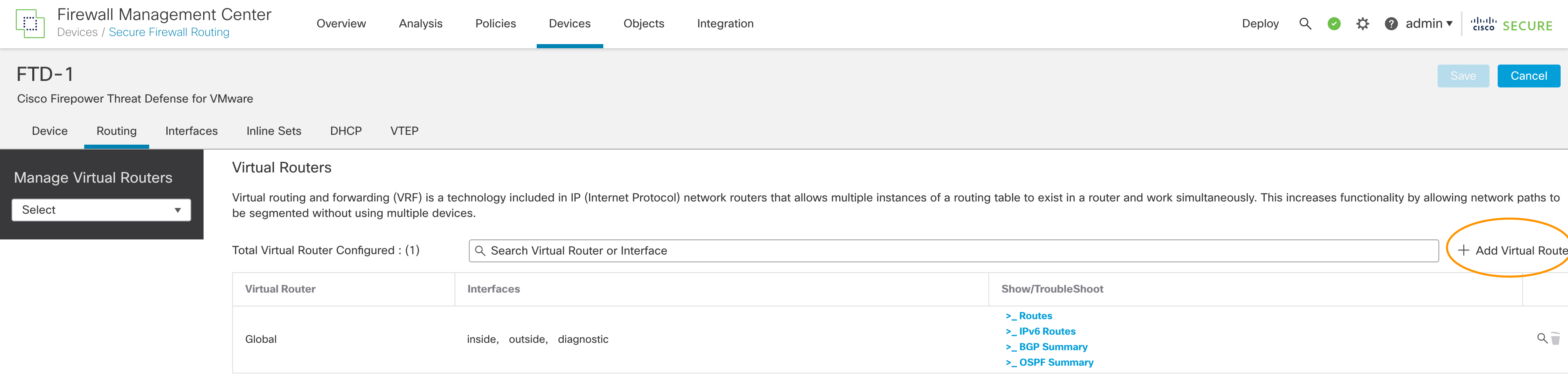
Figure 3: Click "Add Virtual Router"
Step 5: Enter the VRF name and description. Click OK.

Figure 4: New virtual router details
Warning
Verify the VRF name before assigning interfaces to the VRF. The FMC does not allow editing the name of the VRF once it is created. If you wish to change the VRF name, you need to click on Manage Virtual Routers, delete the VRF and recreate the VRF with the correct name.
Step 6: Now, you will be redirected to the Virtual Router Properties page with the newly created VRF selected in the dropdown menu. Select the interface/s from the Available Interfaces and click Add.
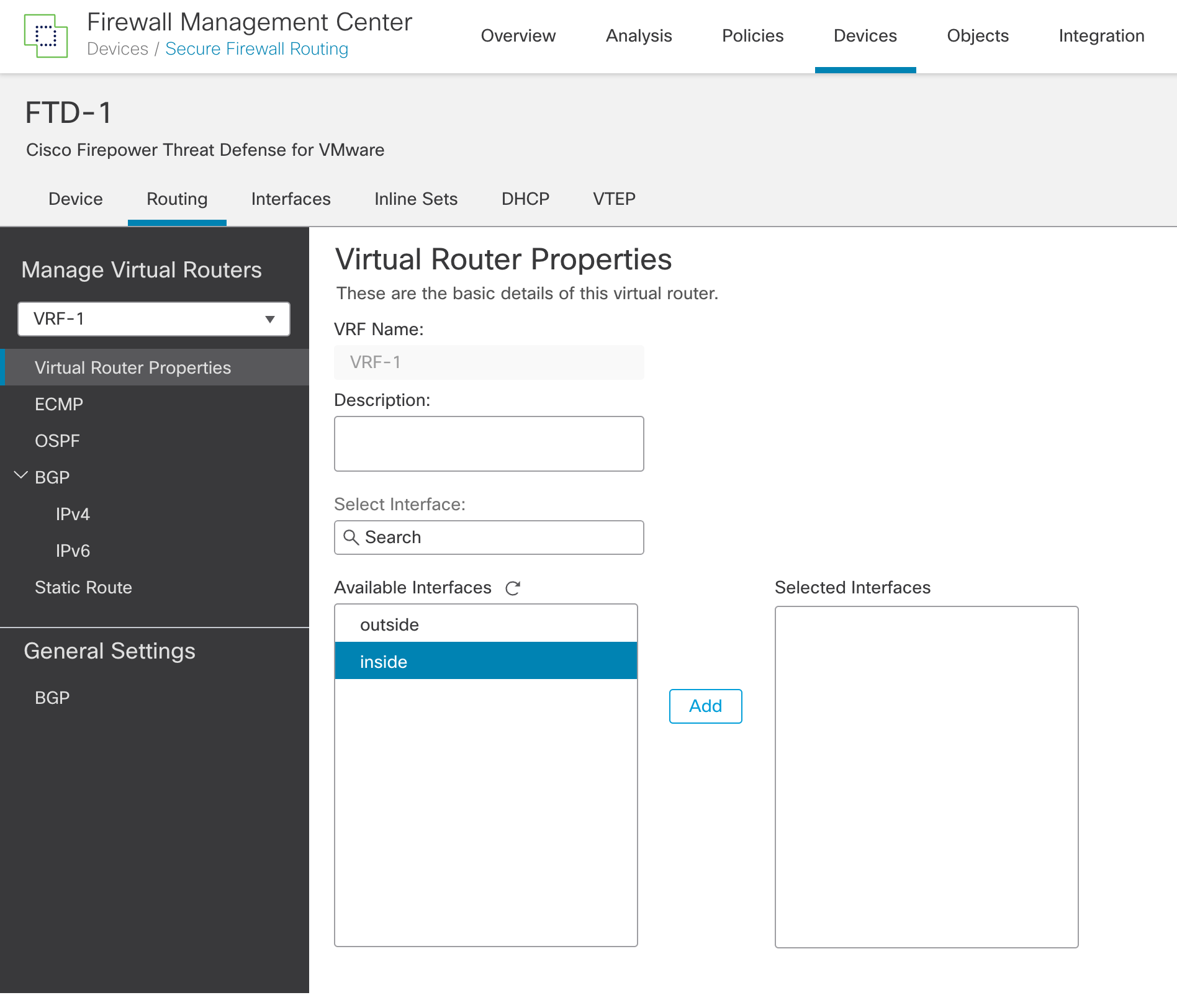
Figure 5: Virtual Router Properties
Note
Available Interfaces only the interfaces configured with a logical name and not assigned to another user-defined VRF are available.
Step 7: You can repeat Steps 3 to 6 for adding more VRFs.
Step 8: Remember to save the changes after adding the VRFs.

Figure 6: Make sure to save your changes!
Step 9: Deploy from the FMC if you are not making any more configuration changes.
Configure Static Routes for VRF
You can use Static routes for intra VRF routing or to leak routes into other user-defined VRFs or the global VRF. When selecting an interface for the static route, the FMC shows the VRF that the interface belongs to.
Step 1: Select the VRF from the dropdown menu under Manage Virtual Routers.
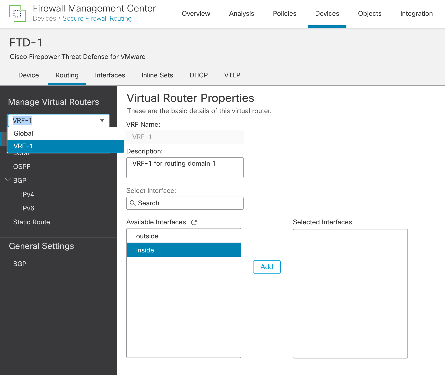
Figure 7: Selecting a user-defined VRF
Step 2: Click on Static Route.
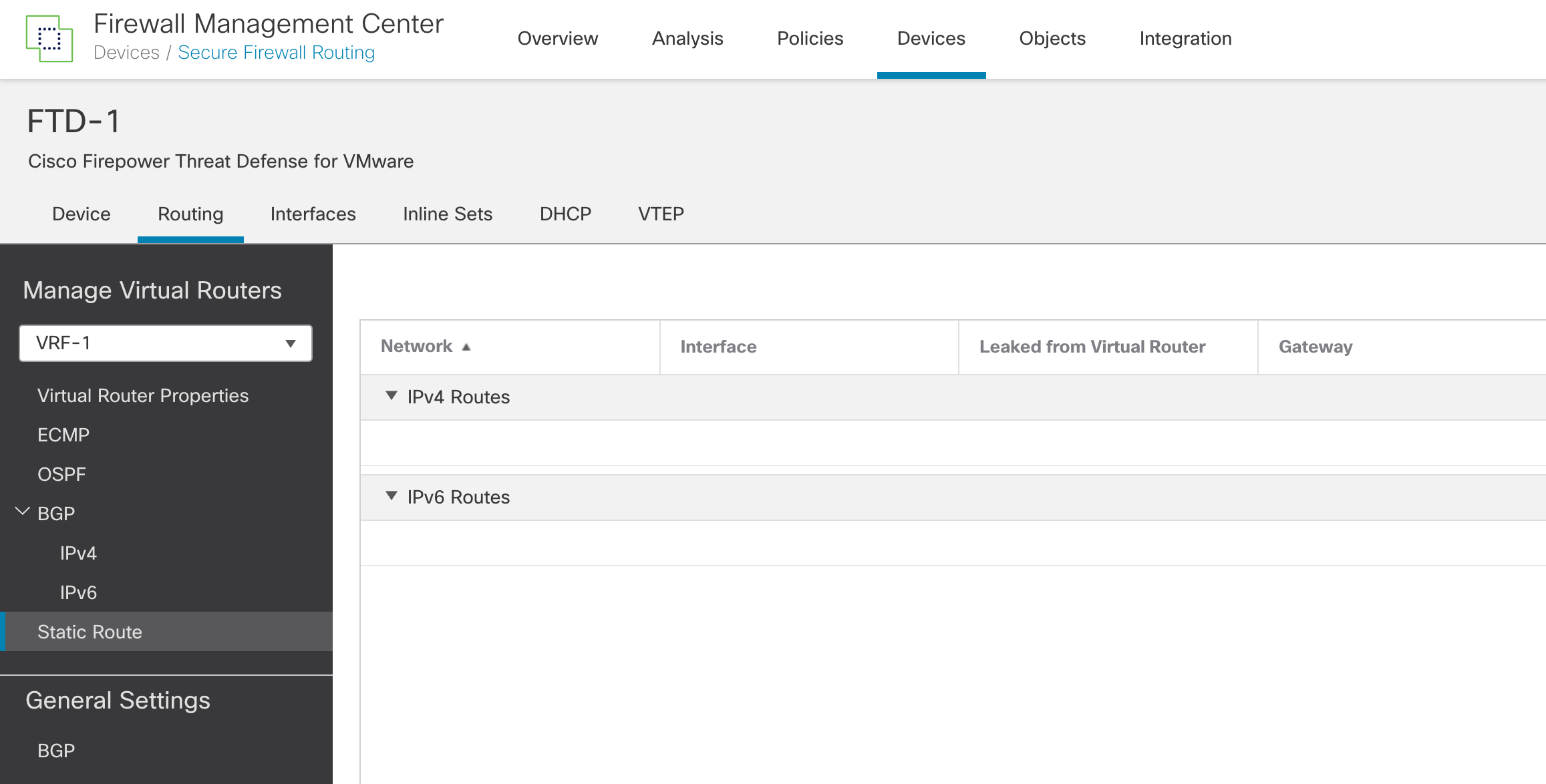
Figure 8: Static routes
Step 3: Click on Add Route.
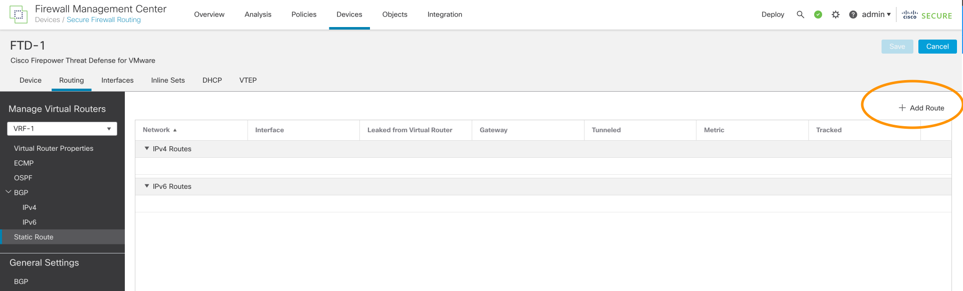
Figure 9: Add Route
Step 4: Select IPv4 or IPv6
Step 5: Select an interface from the interface dropdown list
Note
FMC shows the VRF assignment of each interface. Interfaces that are part of Global VRF have the word Global shown against them. For route leaking, don't specify the next hop.
Step 6: Select Network from the Available Network dropdown list. Click Add to populate the table named Selected Network.
Step 7: Select the next hop from the Gateway dropdown list. If leaking routes, leave this blank.
Step 8: Click OK.
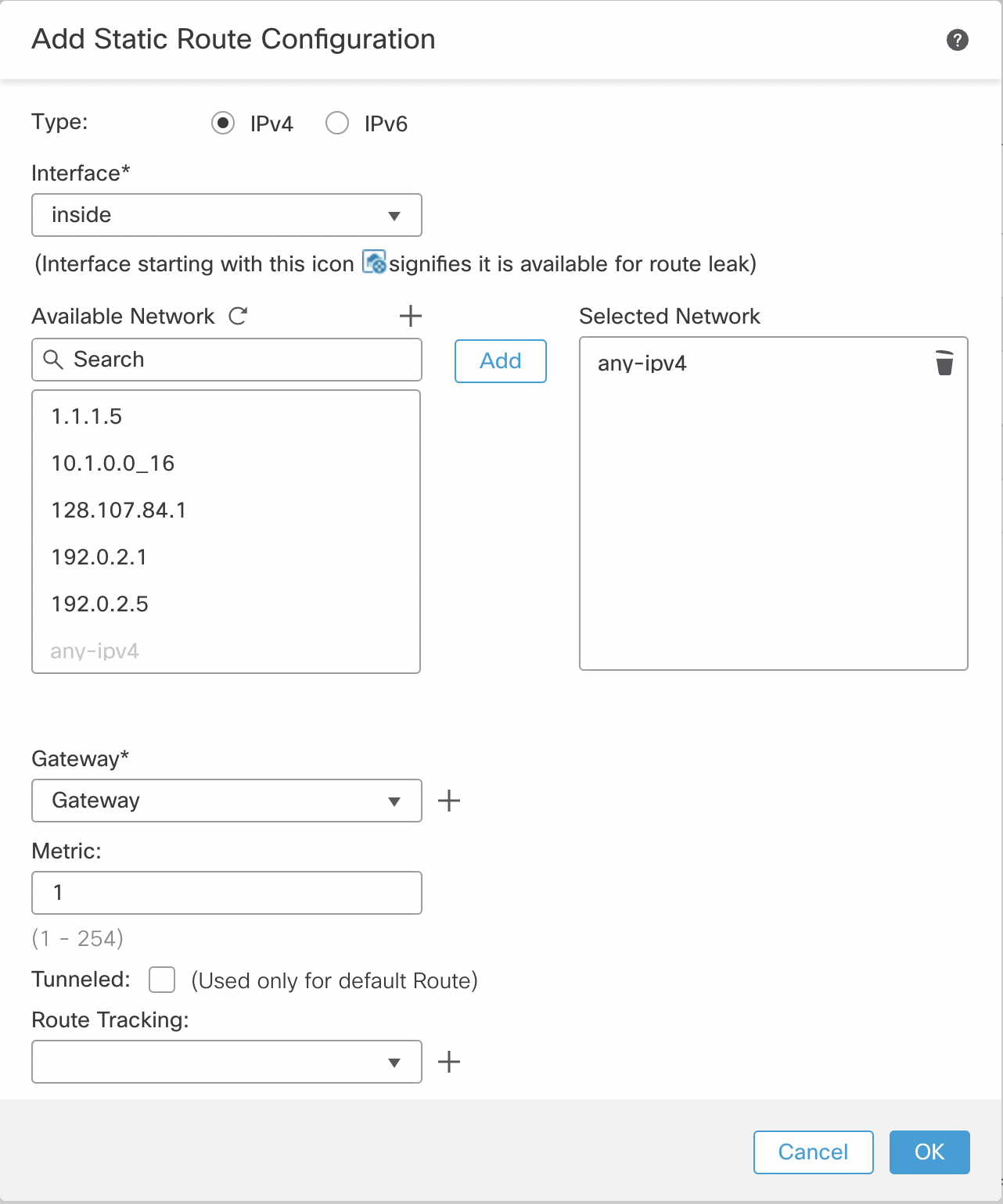
Figure 10: Static route configuration
Step 9: Click Save to save the changes to the VRF configuration.
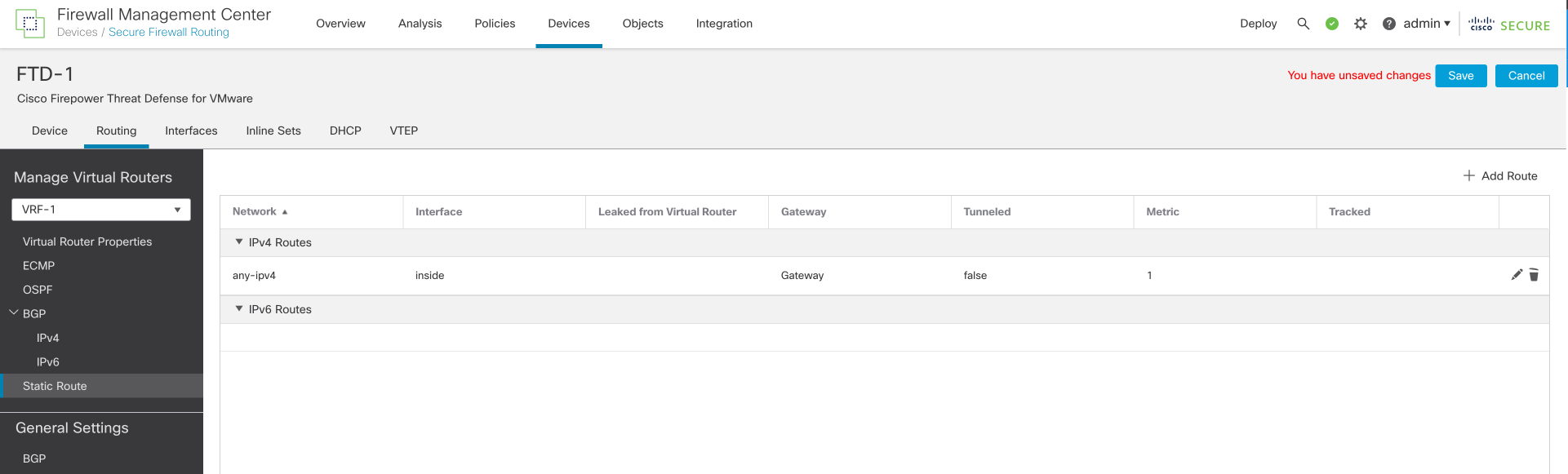
Figure 11: Don't forget to save your changes
Note
You must leak the route in the reverse direction as well if the traffic is not matching any inspection rules such as ICMP inspection. If the Gateway objects don't exist, you can create a new object from the route configuration window.
Step 10: Deploy from FMC if you are not making any more configuration changes.
Configure OSPF for VRF
FTD supports OSPFv2 for user-defined VRFs and OSPFv2/v3 for Global VRFs.
Step 1: Select the VRF from the dropdown menu under Manage Virtual Routers. (See Figure 7)
Step 2: Click on OSPF.
Step 3: Check the Process 1 checkbox.
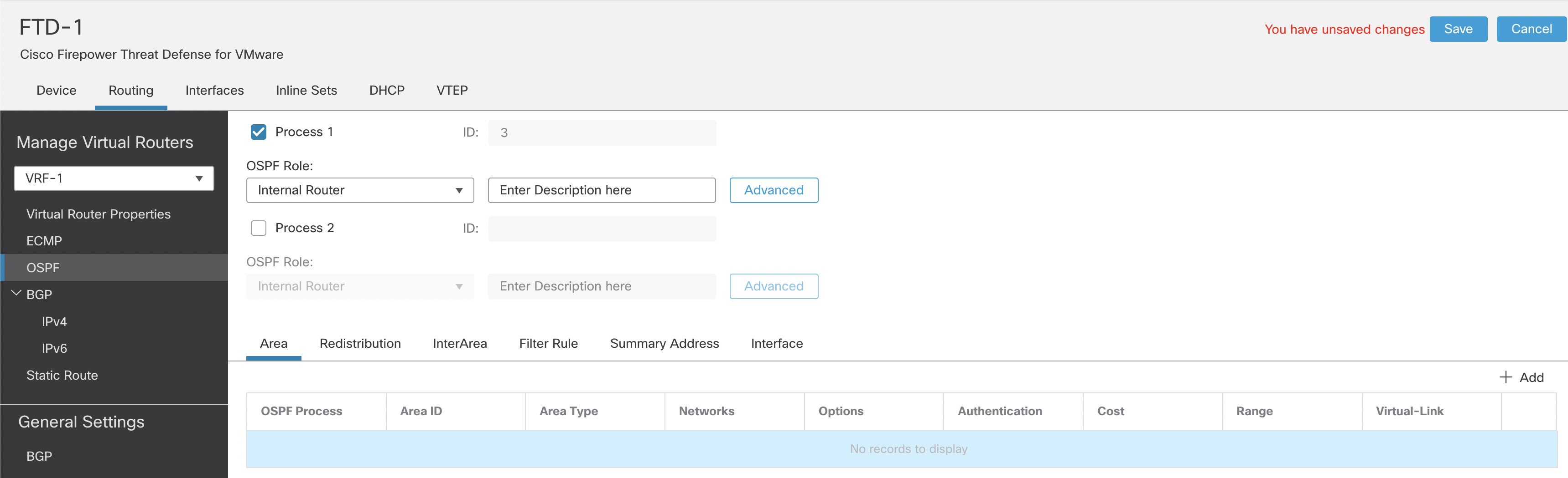
Figure 12: OSPF settings
Note
The Process ID is pre-filled and cannot be changed. FTD allows 2 OSPF processes per VRF. The numbers 1 and 2 are reserved for the OSPF Process IDs in global VRF. The next two numbers, 3 and 4, are allocated to the two OSPF Process IDs in the first user-defined VRFs. This incremental pattern continues whenever OSPF is enabled in the next user-defined VRF.
Step 4: The rest of the OSPF configuration is similar to a non-VRF aware OSPF configuration.
Note
Interface allows you to select only the interfaces of the virtual router that you are configuring. OSPFv3 configuration is available only in the Global VRF.
Step 5: Deploy from FMC if you are not making any more configuration changes.
Configure BGP for VRF
All VRFs share a single BGP process with each VRF as an address family within that process. That is why the BGP configuration is split into two steps. There are general settings (e.g. AS number) and per user-defined VRF settings.
Step 1: In the same column as the Manage Virtual Routers, click on BGP under General Settings (Irrespective of the VRF selected under Manage Virtual Routers).
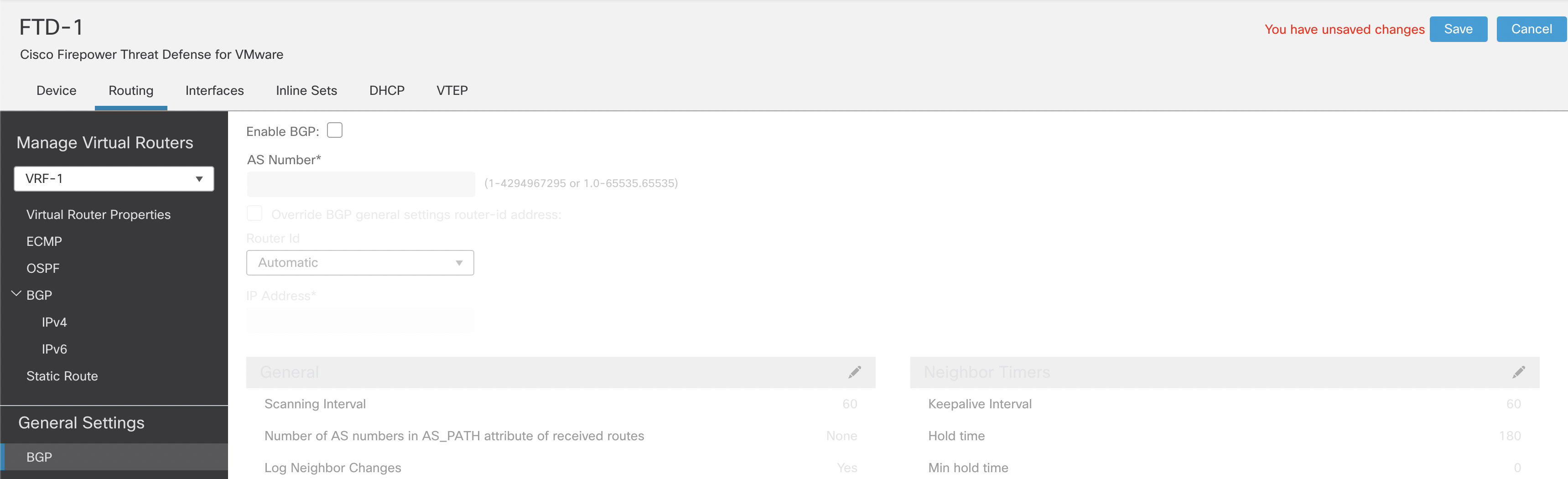
Figure 13: Configuring BGP
Step 2: Check the checkbox named Enable BGP. Enter the AS number.
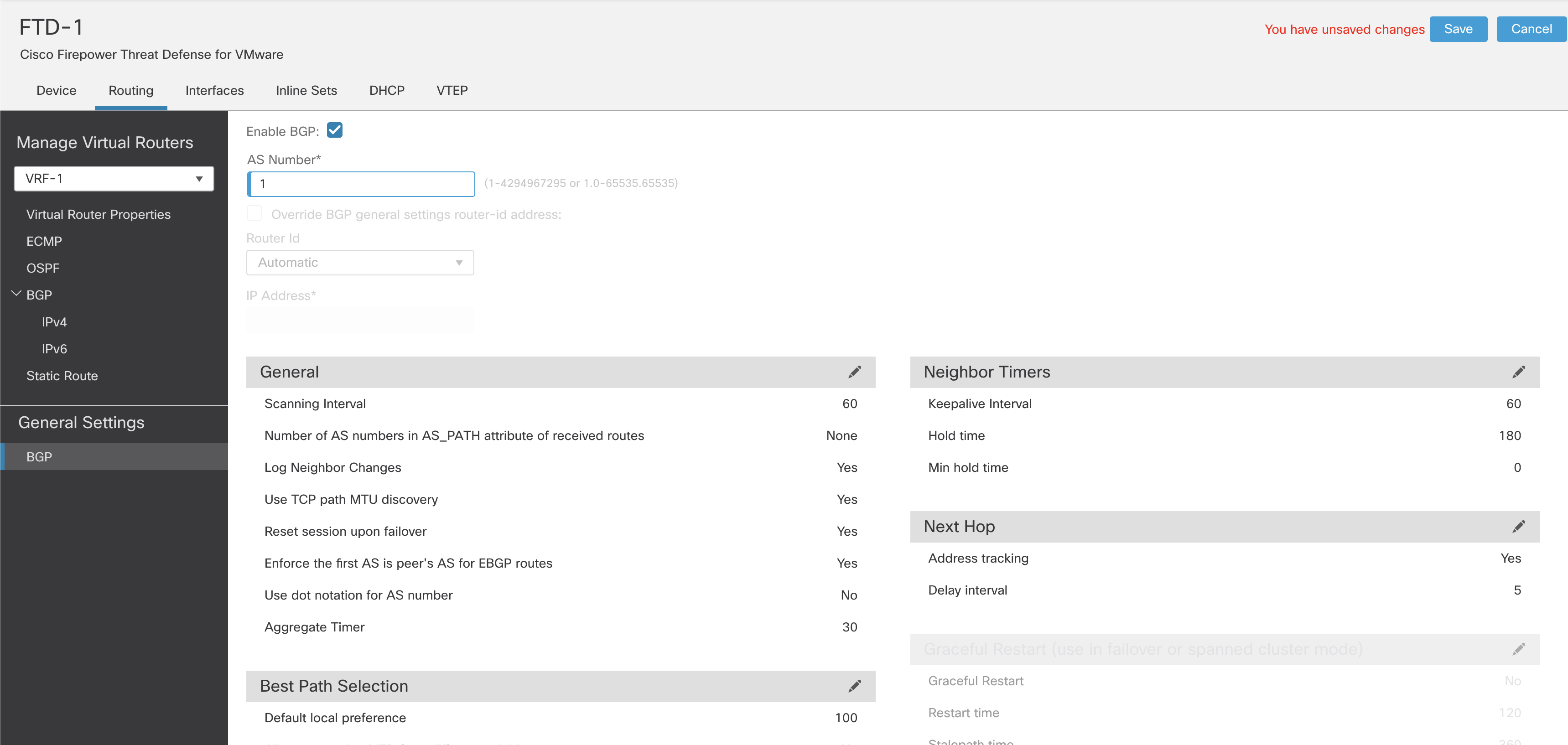
Figure 14: Enabling BGP
Step 3: Configure the rest of the BGP General Settings.
Step 4: Select a VRF from the dropdown menu under Manage Virtual Routers.
Step 5: Click BGP. Configure the BGP settings specific to the selected VRF.
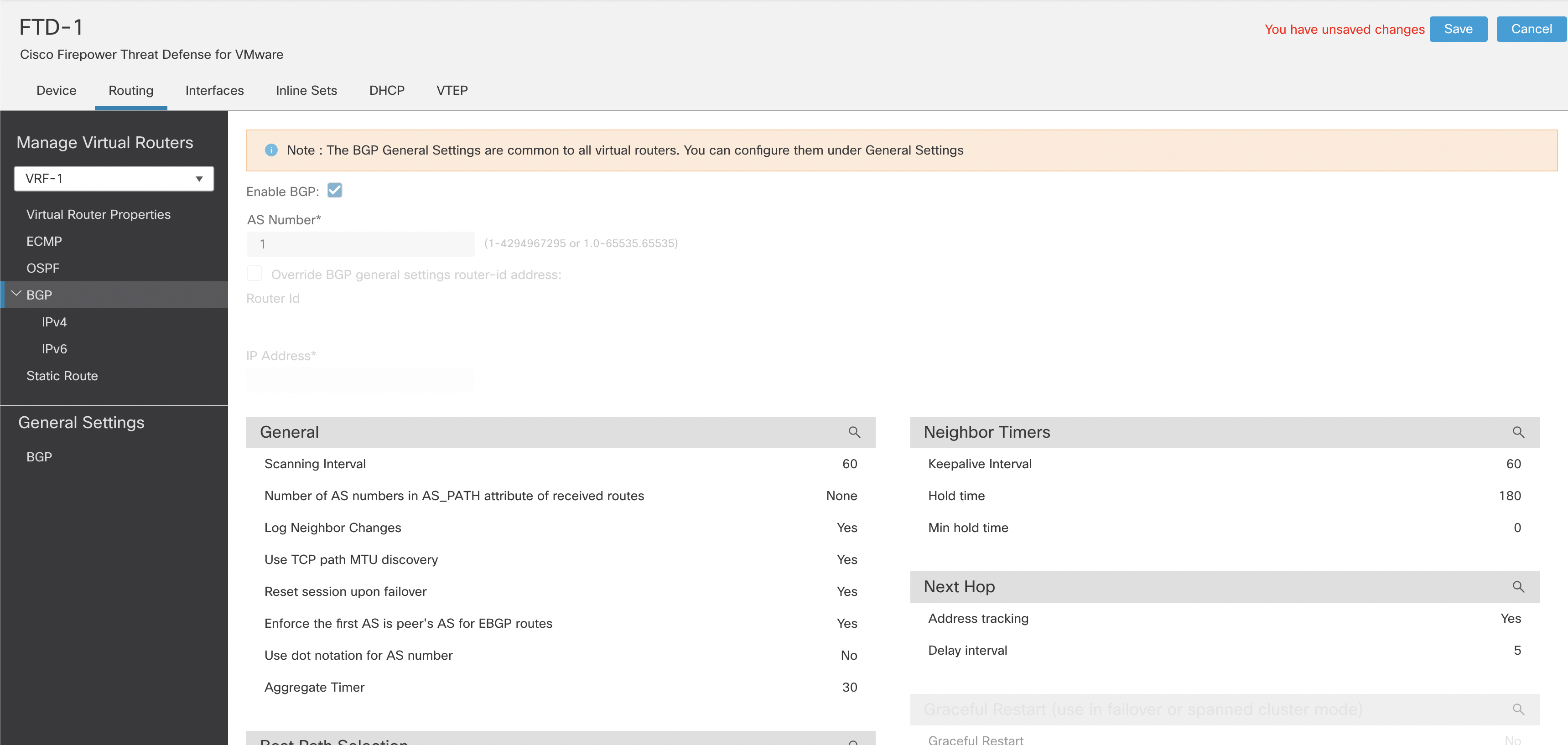
Figure 15: BGP general settings
Note
You cannot change all the global BGP settings within User-defined VRFs. However, you can override the router-Id within each VRF. The rest of the BGP configuration is similar to non-VRF aware BGP configuration.
Step 6: Click IPv4 under BGP. Click on Enable IPv4. Configure the IPv4 address family settings.
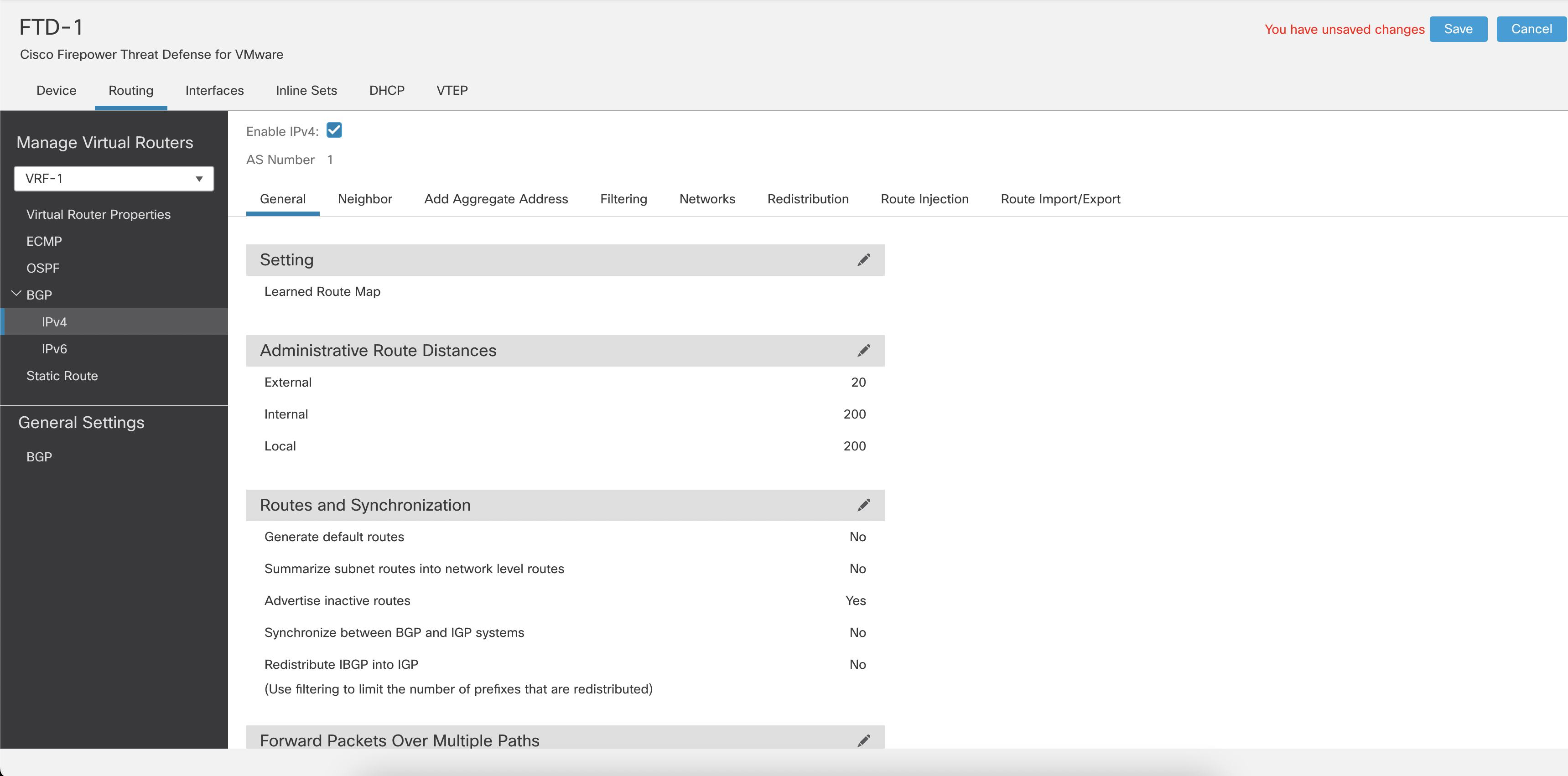
Figure 16: Enabling IPv4 for BGP
Note
User-defined VRFs support BGP IPv4 address family, whereas Global VRFs BGP configuration supports IPv4 and IPv6 address families.
Step 7: Deploy from FMC if you are not making any more configuration changes.
Multi-Instance with VRF
VRF configuration is unchanged when using multi-instance deployments on Secure Firewall platforms. However, instance sizing should account for both throughput requirements and route scale.
Route capacity is not calculated directly from the number of cores assigned to an instance. Instead, each instance size has a supported maximum route scale. Use the route-sizing table or sizing tool to select an instance that supports the required aggregate number of routes across the VRFs in that instance.
For releases through 10.0, an instance can support up to 100 VRFs as long as the total route count remains within the supported route limit for that instance. In release 10.1 and later, the VRF limit increases to 250 VRFs per instance, again subject to the supported route limit within that instance.
When throughput-based sizing and route-based sizing result in different instance sizes, choose the larger instance.
Secure Firewall 4245 route capacity by instance size
The figures below apply to the 4245 appliance. Figures for other appliances will be added soon.
| Instance cores | LINA cores | Max routes, pre-10.1 | Max routes, 10.1+ |
|---|---|---|---|
| 6 | 2 | 3,389 | 33,896 |
| 8 | 2 | 4,938 | 49,389 |
| 10 | 4 | 6,497 | 64,976 |
| 12 | 4 | 8,046 | 80,469 |
| 14 | 6 | 9,577 | 95,774 |
| 16 | 6 | 11,173 | 111,737 |
| 18 | 8 | 12,769 | 127,699 |
| 20 | 8 | 14,366 | 143,661 |
| 22 | 10 | 15,962 | 159,624 |
| 24 | 10 | 17,464 | 174,647 |
| 26 | 12 | 19,061 | 190,610 |
| 28 | 12 | 20,657 | 206,572 |
| 30 | 14 | 22,253 | 222,535 |
| 32 | 14 | 23,849 | 238,497 |
| 34 | 16 | 25,446 | 254,460 |
| 36 | 16 | 27,042 | 270,422 |
| 38 | 18 | 28,638 | 286,384 |
| 40 | 18 | 30,140 | 301,408 |
| 42 | 20 | 31,737 | 317,370 |
| 44 | 20 | 33,333 | 333,333 |
| 46 | 22 | 34,929 | 349,295 |
| 48 | 22 | 36,525 | 365,258 |
| 50 | 24 | 38,122 | 381,220 |
| 52 | 24 | 39,718 | 397,183 |
| 54 | 26 | 41,314 | 413,145 |
| 56 | 26 | 42,910 | 429,107 |
| 58 | 28 | 44,413 | 444,131 |
| 60 | 28 | 46,009 | 460,093 |
| 62 | 30 | 47,605 | 476,056 |
| 64 | 30 | 49,201 | 492,018 |
| 66 | 30 | 50,798 | 507,981 |
| 68 | 32 | 52,394 | 523,943 |
| 70 | 32 | 53,990 | 539,906 |
| 72 | 34 | 55,586 | 555,868 |
| 74 | 34 | 57,183 | 571,830 |
| 76 | 36 | 58,685 | 586,854 |
| 78 | 36 | 60,281 | 602,816 |
| 80 | 38 | 61,877 | 618,779 |
| 82 | 38 | 63,474 | 634,741 |
| 84 | 40 | 65,070 | 650,704 |
| 86 | 40 | 66,666 | 666,666 |
| 88 | 42 | 68,262 | 682,629 |
| 90 | 42 | 69,859 | 698,591 |
| 92 | 44 | 71,455 | 714,553 |
| 94 | 44 | 72,957 | 729,577 |
| 96 | 46 | 74,553 | 745,539 |
| 98 | 46 | 76,150 | 761,502 |
| 100 | 48 | 77,746 | 777,464 |
| 102 | 48 | 79,342 | 793,427 |
| 104 | 50 | 80,938 | 809,389 |
| 106 | 50 | 82,535 | 825,352 |
| 108 | 52 | 84,131 | 841,314 |
| 110 | 52 | 85,727 | 857,276 |
| 112 | 54 | 87,230 | 872,300 |
| 114 | 54 | 88,826 | 888,262 |
| 116 | 56 | 90,422 | 904,225 |
| 118 | 56 | 92,018 | 920,187 |
| 120 | 58 | 93,615 | 936,150 |
| 122 | 58 | 94,835 | 948,356 |
| 124 | 60 | 96,713 | 967,136 |
| 126 | 60 | 98,591 | 985,915 |
| 128 | 60 | 99,530 | 995,305 |
| 130 | 60 | 101,408 | 1,014,084 |
| 132 | 62 | 103,286 | 1,032,863 |
| 134 | 62 | 105,164 | 1,051,643 |
| 136 | 64 | 106,103 | 1,061,032 |
| 138 | 64 | 107,981 | 1,079,812 |
| 140 | 66 | 109,859 | 1,098,591 |
| 142 | 66 | 110,798 | 1,107,981 |
| 144 | 68 | 112,676 | 1,126,760 |
| 146 | 68 | 114,553 | 1,145,539 |
| 148 | 70 | 115,492 | 1,154,929 |
| 150 | 70 | 117,370 | 1,173,708 |
| 152 | 72 | 119,248 | 1,192,488 |
| 154 | 72 | 120,187 | 1,201,877 |
| 156 | 74 | 122,065 | 1,220,657 |
| 158 | 74 | 123,943 | 1,239,436 |
| 160 | 76 | 124,882 | 1,248,826 |
| 162 | 76 | 126,760 | 1,267,605 |
| 164 | 78 | 128,638 | 1,286,384 |
| 166 | 78 | 130,516 | 1,305,164 |
| 168 | 80 | 131,455 | 1,314,553 |
| 170 | 80 | 133,333 | 1,333,333 |
| 172 | 82 | 135,211 | 1,352,112 |
| 174 | 82 | 136,150 | 1,361,502 |
| 176 | 84 | 138,028 | 1,380,281 |
| 178 | 84 | 139,906 | 1,399,061 |
| 180 | 86 | 140,845 | 1,408,450 |
| 182 | 86 | 142,723 | 1,427,230 |
| 184 | 88 | 144,600 | 1,446,009 |
| 186 | 88 | 145,539 | 1,455,399 |
| 188 | 90 | 147,417 | 1,474,178 |
| 190 | 90 | 149,295 | 1,492,957 |
| 192 | 90 | 150,234 | 1,502,347 |
| 194 | 92 | 152,112 | 1,521,126 |
| 196 | 92 | 153,990 | 1,539,906 |
| 198 | 94 | 155,868 | 1,558,685 |
| 200 | 94 | 156,807 | 1,568,075 |
| 202 | 96 | 158,685 | 1,586,854 |
| 204 | 96 | 160,563 | 1,605,633 |
| 206 | 98 | 161,502 | 1,615,023 |
| 208 | 98 | 163,380 | 1,633,802 |
| 210 | 100 | 165,258 | 1,652,582 |
| 212 | 100 | 166,197 | 1,661,971 |
| 214 | 102 | 168,075 | 1,680,751 |
| 216 | 102 | 169,953 | 1,699,530 |
| 218 | 104 | 170,892 | 1,708,920 |
| 220 | 104 | 172,769 | 1,727,699 |
| 222 | 106 | 174,647 | 1,746,478 |
| 224 | 106 | 176,525 | 1,765,258 |
| 226 | 108 | 177,464 | 1,774,647 |
| 228 | 108 | 179,342 | 1,793,427 |
| 230 | 110 | 181,220 | 1,812,206 |
| 232 | 110 | 182,159 | 1,821,596 |
| 234 | 112 | 184,037 | 1,840,375 |
| 236 | 112 | 185,915 | 1,859,154 |
| 238 | 114 | 186,854 | 1,868,544 |
| 240 | 114 | 188,732 | 1,887,323 |
| 242 | 116 | 190,610 | 1,906,103 |
| 244 | 116 | 191,549 | 1,915,492 |
| 246 | 118 | 193,427 | 1,934,272 |
| 248 | 118 | 195,305 | 1,953,051 |
| 250 | 120 | 196,244 | 1,962,441 |
| 252 | 120 | 198,122 | 1,981,220 |
| 254 | 120 | 200,000 | 2,000,000 |
How policies interact with VRF
Assigning the interfaces to different VRFs segments the routing table. However, the Security Policies consider the interface's Security Zone, which implies that the policy evaluation is not VRF aware by default.
Note
The Security Intelligence policy is not VRF aware. If an IP address, domain or URL is blocked as part of Security Intelligence, it will be blocked across all the VRFs.
E.g. If you create a rule with the source zone as "any," it matches the traffic originating from all interfaces across all VRFs.
For applying policies based on VRF, you need to assign the same Security Zone to all the interfaces from a VRF and then use that Security Zone in the security policy.
Overlapping IP addresses
VRFs create mutually exclusive routing tables, enabling FTD to allow overlapping or same address spaces across different VRFs. While creating a security policy, we need to be aware of overlapping IP subnets.
E.g. IP subnet 192.168.1.0/24 exists in VRF-A and VRF-B. The network administrators require users in VRF-A to have Internet access and users in VRF-B to not have Internet access. If you create a security policy that allows Internet access based solely on the source IP network, you will inadvertently allow access to the Internet from both VRFs. You need to assign the interfaces belonging to VRF-A and VRF-B in different Security Zones. Use the Security Zone assigned to the VRF-A interfaces and the source IP network to allow Internet access.
Limitations
Identity policies require different realms per VRF and different ISE connections per VRF to segregate the user-IP and SGT-IP mappings per VRF.
Features such as Threat Intelligence Director (TID), Host Profiling and Malware Trajectory rely on the FMC to map the network. Overlapping IP addresses make it impossible to differentiate when the same IP address belongs to two different hosts. When an overlapping IP segment exists on the same device across multiple VRFs, the analysis from these features is not accurate.
NAT interaction with VRF
FTD uses NAT and/or a routing table for selecting the egress interface and the next hop adjacency resolution. NAT can be used to leak routes across two VRFs and also as a way of enabling communication between overlapping subnets.
Route Leaking using NAT
If you configure NAT rules with the source and destination interfaces in different VRFs, the traffic passes from one VRF to another. However, suppose you do not specify the route lookup option. In that case, the NAT configuration determines the egress interface and the traffic will be sent to the VRF mapped to the destination interface without validating if the destination VRF has a route. We recommended using static routes for route leaking along with a NAT policy configuration.

Figure 37: Route Leaking using NAT
Overlapping IP addresses

Figure 38: Overlapping IP Addresses
If a NAT rule is applied to VRFs with overlapping IP address spaces, ensure that the source interface is specified in a NAT rule for each VRF, ideally with separate NAT/PAT pools. Using 'any' in the source interface causes reverse translation to fail. Even without overlapping IP addresses, using specific interface definitions in the NAT rules is highly recommended.
NAT can enable overlapping subnets to communicate with each other without using BVIs or another network hop, as shown in this example:

Figure 39: Using NAT to enable overlapping IP addresses
Verification and Troubleshooting
show vrf
show route \[vrf name\]

show ospf \[ vrf name \| all\]

show bgp \[ vrf name \| all\]
A special SI route flag shows leaked routes in the routing table.

Figure 40: "show route" output
Number of Supported VRFs per Platform
| Firepower Platform | VRF Limit |
|---|---|
| 1010, 1120 | 5 |
| 1140, 1150, 2110, ISA3000 | 10 |
| 3110 | 15 |
| 2120 | 20 |
| 3120 | 25 |
| 2130, FTDv | 30 |
| 2140 | 40 |
| 3130 | 50 |
| 4110, 4112 | 60 |
| 4115, 4120 | 80 |
| 3140, 4125, 4140, 4145, 4150, 9300 SM-24/36/40/44/48/56 (per-blade) | 100 |
| 9300 with fully populated blades (3x SM) | 300 |
Table 1: VRFs per Platform
Summary
VRF combined with multi-instance can provide true multi-tenancy through routing, security policy and management plane separation.
📚 Additional Resources
More detailed information about VRF is available in the configuration guides for:
Updated about 2 months ago