
Access Control Policy
Cisco Secure Firewall Access Control Policy Guidance
Introduction
This document discusses the Secure Firewall's Access Control feature's key components and configuration best practices using a sample scenario. Configuration steps are based on Secure Firewall Management Center (FMC) v7.2, which may differ slightly from previous versions.
Background Information
One of the essential functions of a firewall is to provide access control by determining which network connections enter your network from the outside or leave your network from the inside. The specifics of what should and should not be permitted are beyond this document's scope, as each network has unique requirements. However, we will provide some best practice guidance on structuring your access policy to protect against malicious activity.
Note
This document focuses on the Access Control policy only. Separate guides are available that cover other policies associated with the access control policy, such as Network Discovery, Intrusion Prevention (IPS), File and Malware.
Access Control
Access Control policies are just one part of the Firewall Threat Defense (FTD) feature set that organizations use to control network traffic. As packets ingress the firewall, many checks occur. For example, is the packet part of an existing connection, and does the packet require decryption or network address translation? Once the packet has had these checks applied, it passes into the Access Control Policy (ACP).
An ACP can be assigned to one or more managed devices. However, a device can only have one ACP deployed at one time. The benefit of assigning a single ACP to more than one device is that a single change to the policy via the FMC UI can quickly be applied to multiple devices, reducing operational overheads.
Network data that is processed by managed devices can be filtered and controlled by a set of rules based on:
-
Simple, easily determined transport and network layer characteristics: source and destination, ports,
protocols and applications -
The latest contextual information on the traffic, including characteristics such as reputation, risk,
business relevance, the application used, or URL visited -
Realm, user, user group, or ISE attribute
-
Custom Security Group Tag (SGT)
-
Characteristics of encrypted traffic; you can also decrypt this traffic for further analysis
-
Whether unencrypted or decrypted traffic contains a prohibited file, detected malware, or intrusion
attempt -
Time and day
Each rule within an access policy requires an associated action determining how to handle the traffic that matches a rule. Figure 1 below details the various rule actions. Additional properties define how to record the activity in the form of logs or alerts.

Figure 1: Access Control rule processing
-
Rule 1: Monitor evaluates traffic first to track and log network traffic. The system continues matching traffic against additional rules to determine whether to permit or deny it.
-
Rule 2: Trust evaluates traffic next. Matching traffic is allowed to pass to its destination without further inspection, though it is still subject to identity requirements and rate limiting. Traffic that does not match continues to the next rule.
-
Rule 3: Block evaluates traffic third. Matching traffic is blocked without further inspection. Traffic that does not match continues to the final rule. (Optional) Interactive Block allows a user to bypass the block if deemed appropriate. Typically, a user-defined warning message is displayed alongside an interactive block explaining the company security policy.
-
Rule 4: Allow is the final rule. For this rule matching traffic is allowed. However, prohibited files, malware, intrusions, and exploits within that traffic are detected and blocked. Remaining non-prohibited, non-malicious traffic is allowed to its destination, though it is still subject to identity requirements and rate limiting. You can configure Allow rules that perform only file inspection, or only intrusion inspection, or no further inspection.
-
Default Action handles all traffic that does not match any of the rules in the ACP. In this scenario, the default action performs a Block All, which is considered best practice in most deployments, as any traffic that hasn't explicitly been allowed or denied per your organization's strategic security policy should be blocked and logged for further analysis.
ACP Default Action
As seen above, each ACP has a default action. A newly created policy (without any custom rules) directs managed devices targeted by that policy to handle all traffic using the default action. When rules are added to the policy by the firewall administrator, the default action applies to the traffic that:
- is not on a Security Intelligence block list
- is not blocked by SSL inspection
- does not match any of the rules in the policy defined by the administrator
The default action can be set to block traffic, trust traffic without further inspection or analyze traffic for intrusion and discovery data.
Access Rule Order
Rules placement in your ACP is important. A specific rule to block traffic can be missed if a more general rule allows traffic above it in the policy. Whereas a rule that allows traffic may never trigger if there is a block rule matching traffic before it.
Another effect on rule ordering is performance. Rules that require further inspection (such as Intrusion Prevention or File and Malware processing) consume more resources. Therefore, it is advisable to remove as many threats as possible using less resource-intensive methods such as blocking traffic using layer-3/4 criteria (such as IP address, security zone and port number).
In general, place rules that are likely to be "hit" the most towards the top of your policy, along with more specific rules. Whenever possible, place specific block rules near the top of the policy so that the firewall can make the earliest possible decision on undesirable traffic, especially if those rules block traffic based on layer-3/4 criteria. Rules that filter on URL or application should come next, followed by the more resource-intensive rules that require the traffic to be processed further by Intrusion and/or file policies.
There are no hard and fast rules on how you structure your ACP. However, the guidelines above will help to ensure that you achieve the best performance out of your firewall. The most crucial factor is having the correct rules to suit your organization's security needs.
Prefilter Policies and Security Intelligence
Before processing network traffic by the Access Control policy, there are additional security checks and controls that can be used to enhance your security posture further. These components bring advantages in terms of performance fine-tuning and security effectiveness.
Prefilter Policies
Prefiltering can be thought of as the first phase of access control before the firewall passes connections onto more resource-intensive evaluation controls. A prefilter policy uses limited, outer-header criteria to process connections quickly. The rule actions available in a prefilter policy are Fastpath, Block and Analyze.
The Fastpath rule action in the prefilter policy bypasses all further packet inspection and handling, including security intelligence, authentication requirements, SSL decryption, access control rules, deep inspection (IPS), network discovery and rate limiting.
Fastpathing traffic is useful where connections are trusted, therefore not requiring further controls or inspection. The real benefit of the fastpath action is improved performance.
The prefilter policy's Block rule action allows the system to block connections at the earliest possible stage as they traverse the firewall. Useful for identifiable connections that can be blocked using basic layer-3/4 criteria, discarding them without requiring too much processing overhead.
The Analyze rule action in the prefilter policy is for all other connections that are not being blocked or fastpathed. The Analyze rule action tells the policy to pass the connections to the next control point in the packet flow process, including sending the connections to the Security Intelligence checks, access control policy and potentially more advanced controls such as NGIPS and Malware control.
Security Intelligence
Security Intelligence (SI) is another early defense against malicious activity applied before passing connections to the access control policy for further processing. SI uses reputation-based intelligence backed by Talos, the threat intelligence organization at Cisco. It can block connections to or from IP addresses, URLs and domain names using a block-list, improving performance by quickly excluding traffic from further inspection.
A Threat license is required to use SI, which enables the regular update of intelligence feeds. Cisco provides intelligence feeds and the option of using supplemental third-party and custom feeds without a license. In addition to custom blocklists, creating custom allow lists allow for overriding SI blocking if required.
Configuration
The following steps guide you by creating a basic Access Control Policy and adding rules to control traffic to traverse a managed firewall.
Best Practice
It is recommended to be as specific as possible with any firewall policy configuration. That is to say, have a full understanding of your company's strategic security policy, user requirements, and business operations. This approach allows you to create an access control policy that blocks unwanted traffic, allows everyday business transactions, and provides auditing that can help in the event of a breach.
This example assumes that the firewall is an Internet-facing, edge firewall protecting a trusted internal network and a semi-trusted DMZ. These scenarios typically have the following requirements:-
- Only allow limited inbound traffic from the outside (Internet) to the inside or DMZ networks
- Provide access to the Internet for web browsing from internal systems and users in a controlled manner
- Provide backend access between the internal networks and the DMZ
- Ensure logging and auditing of connections to assist in troubleshooting
Step 1: Create a new Access Control Policy by navigating to Policies > Access Control
Step 2: Click New Policy

Figure 2: New Access Control Policy Initial Dialogue Screen
Step 2a: Enter a name for the policy along with an optional description.
Step 2b: Choose Block all traffic for the Default Action to ensure that any traffic that isn't matched by rules will be blocked.
Step 2c: Under Targeted Devices, select the firewall or firewalls that this policy will be applied to and click Add to Policy.
Note
You can create a policy without specifying target devices, which is useful if you are designing your policy and do not want to apply it until you are ready.
Clicking Save presents you with an empty policy (Figure 3):

Figure 3: New Access Control Policy (empty)
Step 2d:(optional) Version 7.2 brings an option to try the new UI layout, you can toggle Try New UI Layout button at the upper right of the screen to experience it (Figure 3a):
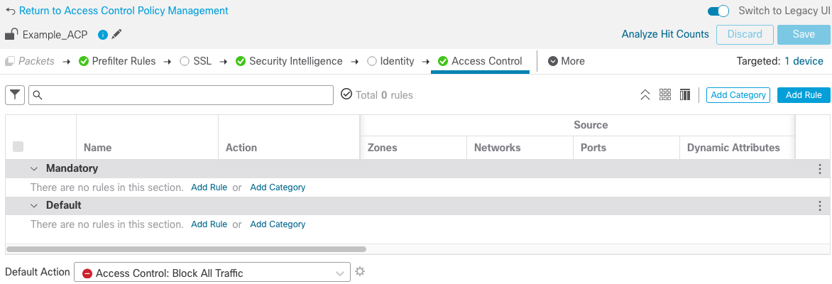
Figure 3a: New Access Control Policy with New UI
Step 3: For consistency, we will continue with the legacy UI, Toggle Switch to Legacy UI to switch back. At this stage, deploying this policy to a managed firewall would block all traffic using the Default Action. Before creating the rules, it's best to create the Network Objects we will use first to reference them in the rules later.
Note
Create objects in the Object Management window or directly from within the Add Rule properties. We'll show both so you can decide which method works best for you.
Step 3a: Navigate to Objects > Object Management and click Network in on the left-hand side.
Step 3b: At the top of the window, click on the Add Network drop-down list and click Add Object.
Step 3c: Complete the fields as shown in Figure 4 below, substituting the IP address for your own:

Figure 4: New Network Object
Step 3d: Click Save
Step 4: Next, add a rule to the Access Policy created in Step 2 to allow web traffic to the server on the DMZ.
Step 4a: Navigate to Policies > Access Control and click on the pencil icon to edit the access control policy.
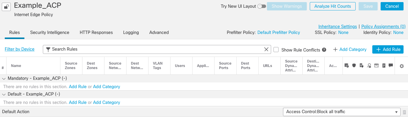
Figure 5: Edit Access Control Policy
Best Practice
It is recommended to lock the policy, in version 7.2 the Access Control Policy Lock feature provides administrators the ability to lock the policy to prevent other administrators from editing it. Left unlocked, if multiple administrators edit the policy simultaneously, the first administrator who save changes wins, and the other administrators lose their changes.
Step 5:To lock the policy and avoid changes being made by other administrators click the Lock icon on the upper left corner of the screen (Figure 6):
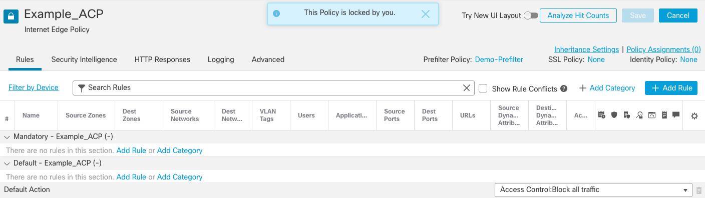
Figure 6: Locked access control policy
Step 5a: Click + Add Rule (over on the top-right hand side)
Step 5b: General rule properties.- Assign a rule Name that helps identify the purpose of the rule without viewing each component in detail.
- The Enabled checkbox allows the rule to be enabled/disabled
- The Action defines how we want the firewall to handle the traffic that matches the rule. In this example,
we want to allow traffic to our web server. - Insert lets you choose where the rule appears in the policy. The position can be changed at any time.
- The Time Range allows you to control when the rule should be active, including setting recurring
schedules. This rule is always active, so we'll leave this set to None.

Figure 7: General Rule Properties
Step 5c: Now configure the rule matching criteria. The first tab adds Zones, which in this example from the list of zones available, we've added DMZ to Destination and Outside to Source.
Note
Create Zones under Objects > Object Management > Interfaces or during device configuration and are used to represent security zones made up of one or more interfaces.

Figure 7a: Adding Zones to the access rule
Step 5d: Next, we move to the Networks tab. Here we can control which source/destination networks/hosts we want to communicate. Figure 8 shows the completed Networks tab.
- In our example, we're hosting a public webserver with a source network of ANY, which is the default for
both source and destination. - For the destination, look in the list of available networks, select Webserver_Public and click Add to
Destination.
Note
If the network object doesn't exist, you can create one "on the fly." To the right of the "Available Networks" click the + sign to create a new network object, as seen in Step 4c.

Figure 8: Configuring Network object controls
Step 5e: The Applications allow the firewall to inspect the traffic to ensure that the correct applications access resources. Again, in our example, we are hosting a public webserver, so the applications we want to allow are HTTP and HTTPS.
- From the list of Available Applications, type HTTP in the search box. Then select HTTP,
HTTPS and click Add to Rule.
Note
Application Visibility and Control (AVC) causes the firewall to inspect the payload of network connections, verifying that the connections contain the allowed application to prevent malicious actors from tunneling different applications across standard ports. Traditional port-based rules would miss this activity. Combining applications and ports to force applications to use a particular port number provides better access control. For example, configuring HTTP as the destination application and 80/tcp as the destination port ensures all HTTP connections occur over port 80/tcp. With no port specified, then HTTP as an application would be accepted over any tcp port.

Figure 9: Adding applications to our matching criteria
Step 5f: The final step in our example rule is to define the Logging options. Move to the Logging tab and check the following boxes:
-
Log at Beginning of Connection
Creates a log event when connections are established. -
Log at End of Connection
Creates a log event when connections are closed. -
Send Connection Events to Event Viewer
Sends events to the internal event viewer for review.
Best Practice
Logging settings depend on your security strategy and regulatory compliance requirements. In general, only log at both the beginning and end of connections to capture audit information such as the duration of connections and the number of bytes sent/received.
- Click Add

Figure 10: Logging options
Step 6: Now that the rule is configured, create a Network Address Translation (NAT) rule so the firewall can forward packets that arrive destined for the webserver's public IP address to its private (internal) address on the DMZ.
Step 6a: Navigate to Devices > NAT. Click New Policy and select Threat Defense NAT.
Step 6b: Give the Policy a name and add your firewall device to the policy by clicking the device name under Available Devices and then clicking Add to Policy.
Step 6c: Click + Add Rule. We're going to use an Auto NAT Rule in our example to translate connections arriving at the firewall for the webserver. Auto NAT is the simplest form of NAT where the NAT rule becomes a parameter for a network object. The network object IP address serves as the original (real) address. Complete the rule using the detail below and figure 11 as reference.
- Under NAT Rule, select Auto NAT Rule.- For Type, select Static
- On the Interface Objects tab, select DMZ for the Source Interface Objects and Outside for the Destination Interface Objects.
- On the Translation tab, select Webserver_Private as the Original Source and for Translated Source, select Address > Webserver_Public- Click Ok and save the NAT policy.

Figure 11: Auto NAT Rule
Step 7: Repeat Steps 4 to 6 to complete objects, rules and NAT for inbound SMTP (mail) access. Create objects that reference the relevant IP addresses for the public and private address for your mail server.
Step 8: Next, create a rule to allow general Internet access from the inside network. If not already open, Navigate to Policies > Access Control and edit your access control policy by clicking the pencil icon.
Step 8a: Click +Add Rule and configure the general rule options as below in Figure 12:

Figure 12: Outbound Internet rule general options
Note
We're inserting the rule below rule number 2 (our Inbound Web Access rule) as this follows our best practice of placing more specific rules above more general rules.
Step 8b: As done in the Inbound Web Access rule, add the matching criteria for the rule, including zones, applications and logging options. Use the following example settings:
-
Zones tab: Source Zone = Inside, Destination Zone = Outside Figure 13
-
Applications tab: Add DNS, HTTP, HTTPS and FTP to the Selected Applications and Filters box Figure 14
-
Logging tab: Check both Log at Beginning & End of Connection and Send Connection Events to Event Viewer Figure 15

Figure 13: Configure Zones

Figure 14: Add Applications to the rule

Figure 15: Configure Logging Options
Step 8c: Click Add and then click Save to commit your changes to the policy.

Figure 16: Access Control Policy so far
Step 8d: To accompany the Outbound Internet rule, we need a NAT rule for connections that originate from our internal (private) network, going to the Internet with a valid, publicly routable IP address. Navigate to Devices > NAT and edit your NAT policy by clicking the pencil icon.
Step 8e: Click +Add Rule. This time we're going to use a Dynamic Auto NAT Rule to translate connections leaving the firewall from inside to outside by translating them using a range of public IP addresses. Complete the rule using the detail below and Figure 17 as reference.
-
Under NAT Rule, select Auto NAT Rule.
-
For Type, select Dynamic
-
On the Interface Objects tab, select Inside for the Source Interface Objects and Outside for the Destination Interface Objects.
-
On the Translation tab, select your internal subnet as the Original Source and for Translated Source, select Address and then click the + sign to add a new network object.
-
Give the new object a name (e.g. Example_NAT_Pool), select Range, and enter a valid public IP address range from your available public address space. Enter the range in the form of x.x.x.x-x.x.x.x (see Figure 18 as an example).
Note
A more straightforward way of achieving this is to have all outbound traffic use the outside interface's IP address as a translated source address to negate the need to create a NAT pool/range object. This configuration is useful for smaller or remote office deployments where the number of concurrent outbound connections is relatively low.
- Click Save to save the new network object and select it from the drop-down list under Translated Source.- Click Ok and save the NAT policy.

Figure 17: Dynamic Auto NAT rule

Figure 18: NAT Pool object example
Step 8f: Apply URL control to access control rules (optional). If you have a URL license for your deployment, it is possible to control the categories of websites that your users can access. URL control uses the Talos web category database that provides control of 85+ content and threat categories.
Step 8g: Navigate to Policies > Access Control and edit your access control policy by clicking the pencil icon. Edit the rule created above in Step 8a Outbound Internet).
Step 8h: Move to the URLs tab for the rule and add the categories you want to allow (or deny if the rule is a block rule) to the Selected URLs box.
Note
You can control access based on ANY URL within a category or URLs with a specific reputation score.

Figure 19: (Optional) URL Category Control
Step 9: The final rule in our example is to allow connections between the inside network and the DMZ for backend communications between the web server and internal databases or for other required application traffic. This rule does not require NAT, as the DMZ networks and inside are private, so we control the routing. However, to add additional security, we will see how to attach Intrusion Prevention, File and Malware control to the access policy rules.
Note
A valid THREAT license (subscription) is required to use Intrusion policies, and a valid Malware license (subscription) is required to enable Malware & File control.
Step 9a: Before we add a rule to our access control policy, we need to create a File & Malware policy to attach to our new rule. Navigate to Policies > Malware & File and click New File Policy. Give the file policy a name, e.g. Block Malware & Executables

Figure 20: New File Policy
Step 9b: Click +Add Rule and configure as per Figure 21 below to block executable files and click Save.

Figure 21: Block executable files
Step 9c: Click +Add Rule again and configure as per Figure 22 below to block traffic identified as containing malware.

Figure 22: Block Malware rule
Note
Under File Type Categories, select all except for Executables (we're blocking these in the previous rule), Dynamic Analysis Capable and Local Malware Analysis Capable.
Step 9d: Click Save to save the rule and then Save again to commit the changes to our Malware & file Policy.
Step 9e: Navigate to Policies > Access Control and edit your access control policy by clicking the pencil icon. Click +Add Rule and complete the general rule options as shown here in Figure 23.

Figure 23: General Rule Policy
Step 9f: Next, add a rule to allow ANY connections between the Inside and DMZ zones.Note: After adding the zones, all other tabs can be left as default (any).

Figure 24: Zone configuration
Step 9g: To add Intrusion Prevention (IPS) to traffic that matches this rule, move to the Inspection tab and select the Balanced Security and Connectivity Intrusion Policy. Using this base policy adds a default SNORT policy to the rule to identify threats and vulnerabilities that may be present in the traffic. IPS is backed by Cisco's Talos organization, which is comprised of world-class threat hunters and security intelligence gathered worldwide.

Figure 25: Next Generation Intrusion Policy selection
Step 9h: For File Policy, select the Malware & File Policy we created in Step 9a.

Figure 26: Malware & File Policy selection
Step 9i: Click Save to save the rule. Your Access Control Policy should look similar to Figure 27:
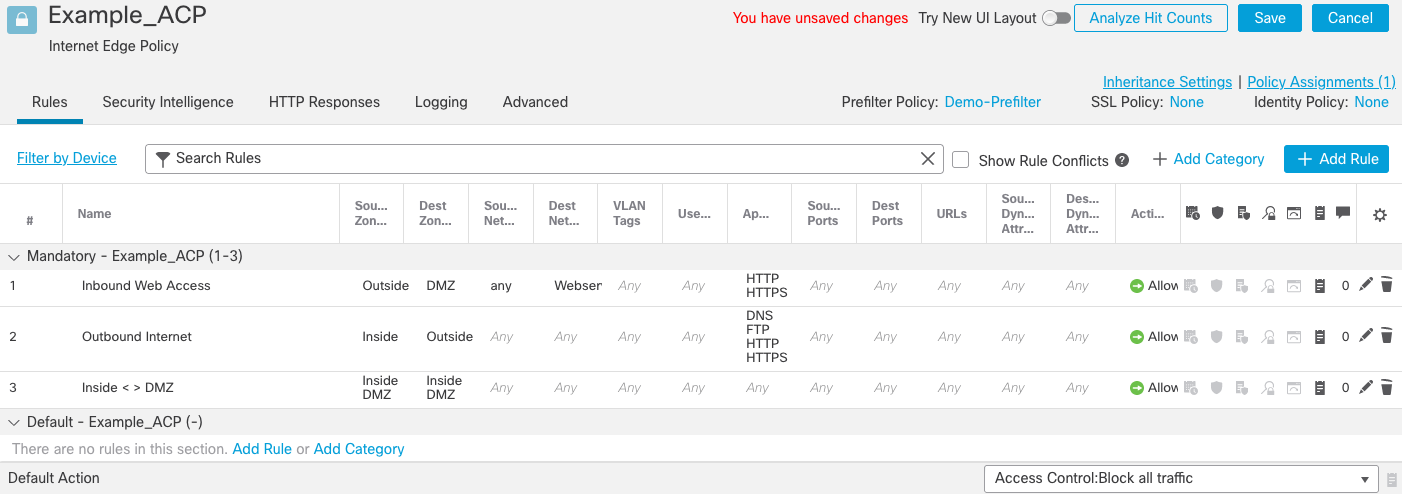
Figure 27: Completed Access Control Policy
Note
For the last rule, notice that the Intrusion Policy and Malware & File Policy icons are active. The icons indicate that the rule has advanced inspection options enabled.

Figure 28: Intrusion and File & Malware policy icons
Step 9: Click Save to save the changes to the access control policy.
Step 10: The access control policy is now ready to deploy to your device. Navigate to Deploy > Deploy this device icon to the right of the device to begin deployment.
Step 11 Once the deployment begins click on the Lock icon to Unlock the access control policy so that other administrators can make additional changes to the policy if needed.
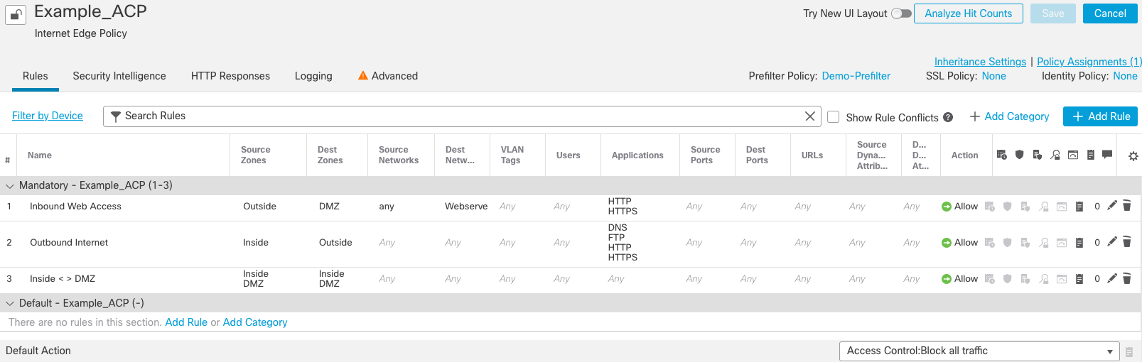
Figure 29: Completed Access Control Policy (unlocked)
Verification/Troubleshooting
To verify your configuration, check that you can access devices/networks as per your access rules. For example, check that a device (e.g. a web browser) can access your webserver from the Internet. Also, check that users on the internal network can access the Internet.
If connectivity isn't as expected, check the event logs for details. Remember, we enabled logging on all rules to get this valuable information.
Navigate to Analysis > Unified Events and verify that you can see connection events related to your activity. Then confirm that the action for that event is what you expect (e.g. allowed/blocked). If not, verify your access control policy rules have the correct action defined. It's a common mistake to create a rule and forget to change the action to the desired option.
Summary
Access Control policies are a crucial component of your Secure Firewall deployment. They allow you to map your organization's security strategy and policies to the network connections traversing your firewall or firewalls. Granular and flexible, they enable configurations that protect and control up to the application layer. When combined with Intrusion and Malware policies, the firewall becomes a powerful, multifaceted threat defense solution.
📚 Additional Resources
For more information about the Cisco Secure Firewall, please see the following resources:
Updated about 4 years ago