
VXLAN and GENEVE Support
Cisco Secure Firewall VXLAN and GENEVE Support
Introduction
The Cisco Secure Firewall uses VXLAN and GENEVE protocols to implement three distinct features.
- Virtual firewall clustering support
- AWS Gateway Load Balancer (GWLB) integration
- VXLAN tunnel termination for generic VXLAN communication referred to in this document as generic VXLAN use.
This document describes the implementation of these protocols for both Cisco Secure Firewall ASA (ASA) and Cisco Secure Firewall Threat Defense (FTD). However, the focus is on FTD.
New in the Firewall Management Center (FMC) Release 7.2 is the ability to configure generic VXLAN use.
- Clustering virtual FTD firewalls is also new with 7.2. Please refer to Clustering Virtual Firewalls for which this document is a suggested prerequisite.
- For Cisco Secure Firewall integration with the AWS GWLB, see the reference section of this document.
VXLAN and GENEVE Technology
VXLAN and GENEVE are both network virtualization over layer 3 (NVO3) protocols used to create overlay networks.
| VXLAN | GENEVE |
|---|---|
| Stands for Virtual eXtensible Local Area Network | Stands for Generic Network Virtualization Encapsulation |
| Fixed header format | Extensible header format |
| Overcomes scaling challenges in large cloud deployments (you can have up to 16,777,215 VXLANs) | Accommodates changing virtualization capabilities and needs |
| Generally encapsulated in UDP port 4789 | Generally encapsulated in UDP port 6081 |
Below are the header formats. Note the extensible header format for GENEVE.
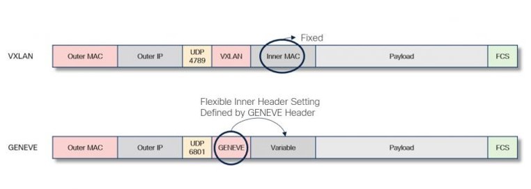
VXLAN and GENENE headers
Below is key terminology common to both VXLAN and GENEVE configuration on the Cisco Secure Firewall.
- VTEP - Virtual Tunnel End Point
- Data interface that performs transmission between peers
- NVE - Network Virtual Edge
- Specifies encapsulation protocol (GENEVE or VXLAN)
- Performs encapsulation/de-encapsulation
- Specifies VTEP (nameif of VTEP interface)
- VNI - Virtual Network Interface
- Virtual interface used as source and destination of the tunneled traffic
- Specifies the NVE
- Multiple VNIs can use the same NVE.
Note that in non-clustered Cisco Secure Firewalls there can only be one VTEP and one NVE. The NVE and VTEP can support multiple VXLANs. However, each VXLAN has a separate VNI.
VXLAN and GENEVE Support in Cisco Secure Firewall
Note
Although VXLAN and GENEVE technologies are similar, their uses in the Cisco Secure Firewall are distinct.
VXLAN GENEVE Custer link for virtual firewall clusters Not used for cluster link Not used to communicate with load balancers Used to communicate with AWS GWLB Firewalls can use VXLANs to tunnel generic network traffic. This document refers to this as generic VXLAN use. Firewalls cannot use GENEVE to tunnel generic network traffic.
The ASA has long supported VXLANs. The 6.2 release extended this functionality to FTD. However, prior to 7.2, VXLAN configuration on FTD required two steps:
- VTEP and NVE configuration required FlexConfig.
- VNI configuration was natively available in the FMC UI.
The 7.1/9.17.1 release introduced GENEVE support for FTDv and ASAv on AWS. The ASDM, CSM and FMC all provide configuration support. Cisco Secure Firewalls only use GENEVE encapsulation for integration with the AWS GWLB.
The 7.2 release added native VXLAN support to the FMC UI and API. VXLAN configuration with the FMC is the central topic of this document.
Caution
If you configured VXLAN interfaces with FlexConfig in a previous version, they continue to work. In fact, FlexConfig takes precedence in this case. If you redo your VXLAN configurations in the web interface, remove the FlexConfig settings.
Cluster Support for General VXLAN Use
Configuring VXLANs on firewall clusters faces limited due to the fact that you cannot use an NVE for both cluster communication and VXLAN communication.
Physical Firewall Clusters
Physical firewall clusters do not require an NVE for the cluster communication link (CCL). Therefore, physical clusters support the generic VXLAN use configuration described below. To use the configuration described below you must first configure Etherchannel for the VTEP interface. You cannot use individual interface mode.
Virtual Firewall Clusters
Virtual firewall clusters do not support generic VXLAN use. Deploying the clusters creates the VXLAN configuration for the cluster control link (CCL).
- In the public cloud, bootstrapping prior to registration with the FMC creates the cluster. Once registered.
- In the private cloud, build clusters using registered FTDs. Building a cluster using FTDs with VXLAN configurations, will create an error.
In either case, after the cluster configuration, the VTEP/NVE and VNI configuration is read-only in the FMC.
See the references for details about clustering virtual firewalls.
AWS GWLB Deployments
If you can only configure one NVE in the FMC and wish to put the FTDs behind an AWS GWLB, you must configure the NVE for GENEVE support. Therefore, you cannot deploy generic VXLAN use behind a GWLB. The ASA has a similar limitation.
FMC Configuration of Generic VXLAN Use
High Level Configuration
- Navigate to Devices > Device Management > Device Edit > VTEP.
Create the NVE and assign the VTEP. - Navigate to Devices > Device Management > Device Edit > Interfaces.
Create and configure the VNI interfaces, one for each VXLAN. - Configure routing and access control policy rules as needed for the VNI interfaces.
Configuration Details
Configure NVE and Add a VTEP
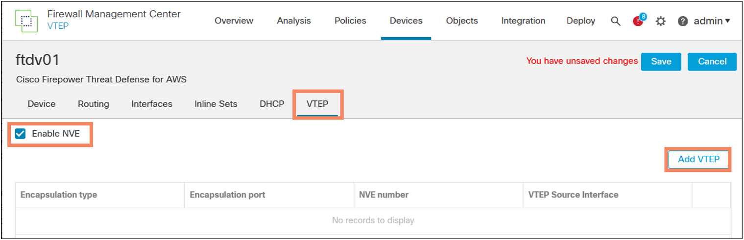
- Navigate to Devices > Device Management > Device Edit > VTEP.
- Check Enable NVE.
- Click Add VTEP.
️ Note
Add the VTEP for an FTDv deployed in AWS has two encapsulation options: GENEVE or VXLAN. Choose GENEVE to configure communication with the AWS GWLB. On all other platforms the encapsulation option is set to VXLAN and greyed out.
You cannot manually configure two NVEs.
Configure the VTEP Attributes
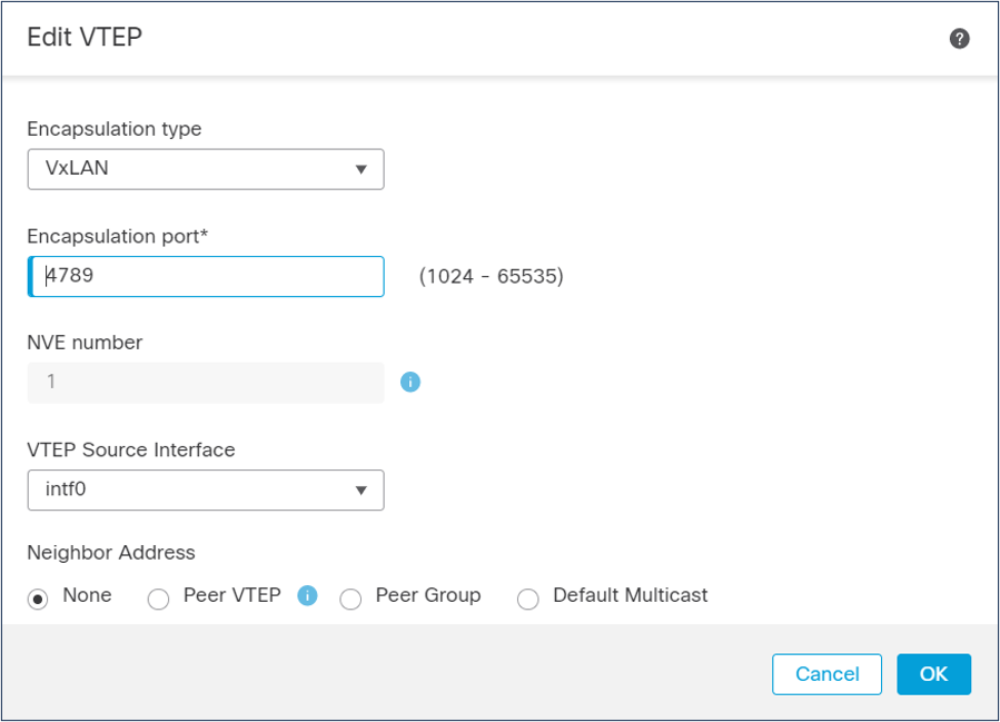
The FMC exposes the following attributes.
- Encapsulation type. On AWS select VxLAN. On all other platforms you cannot modify this attribute.
- Encapsulation port. Specify the UDP port used for all VXLAN traffic.
- NVE number. is always 1 for non-clustered firewalls and you cannot modify this attribute.
- VTEP Source Interface. Select the VTEP interface nameif. The FMC automatically updates the MTU value of the interface to 1554, eliminating the need to enable jumbo frames. The interface must be one of the following types. Subinterfaces cannot be VTEPs.
- Data plane interface.
- Port channel
- Redundant interface
- Neighbor Address. options.
- None. Configure peer or peers later. You will also see this setting for the CCL link
- Peer VTEP. Enter the IPv4 address of the peer.
- Peer Group. Select an IPv4 network object. Cluster bootstrapping uses this attribute value.
- Default Multicast. Configure the default IPv4 multicast address for all the VNIs. You can override this configuration when you configure the VNIs.
Mapping multiple VXLAN segments to a single multicast group can help conserve multicast control plane resources and achieve the desired VXLAN scalability. However, this mapping comes at the cost of suboptimal multicast forwarding. The firewall will send all packets for all VXLANs to every peer VTEP.
Add and Configure the VNIs
- Navigate to Devices > Device Management. Edit the appropriate device and select the Interfaces tab.
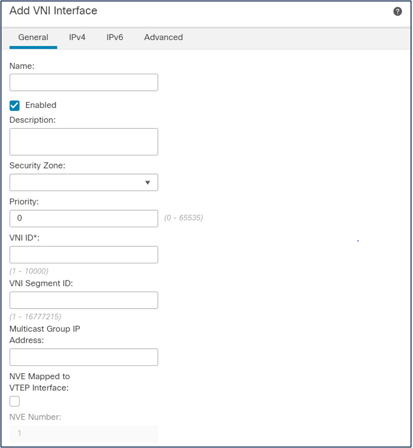
- Click Add Interface > Add VNI Interface.
- The following information is mandatory for generic VXLAN use.
- Name. The nameif of the VNI
- Segment ID. This number, included in the VXLAN header, identifies the VXLAN. This can range from 1 to 16777215
- VNI ID. The firewall uses this attribute internally to identify the VNI. This can range from 1 to 10000.
- VNI Mapped to VTEP Interface. You must check this checkbox.
- An IPv4 address, IPv6 address. Select a static address or DHCP
️ Note
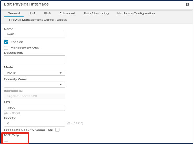
Optionally, you can restrict traffic through the VTEP to the VXLAN traffic. This does not restrict traffic to or from the VTEP itself. For example, you should still be able to ping between the VTEP and its peer, provided your network infrastructure allows ICMP.
- Navigate to Devices > Device Management. Edit the appropriate device and select the Interfaces tab.
- Edit the VTEP interface. The 7.2 release adds a checkbox: NVE Only.
FMC API
The 7.2 FMC provides a comprehensive set of API commands for VXLAN configuration. There are (essentially) two API URLs. The first is for configuring the NVE and VTEP.
| Method | URL |
|---|---|
| GET | /api/fmc_config/v1/domain/{domainUUID}/devices/devicerecords /{containerUUID}/vteppolicies |
| GET (by ID) | /api/fmc_config/v1/domain/{domainUUID}/devices/devicerecords /{containerUUID}/vteppolicies/{objectId} |
| POST | /api/fmc_config/v1/domain/{domainUUID}/devices/devicerecords /{containerUUID}/vteppolicies |
| PUT | /api/fmc_config/v1/domain/{domainUUID}/devices/devicerecords /{containerUUID}/vteppolicies/{objectId} |
| DELETE | /api/fmc_config/v1/domain/{domainUUID}/devices/devicerecords /{containerUUID}/vteppolicies/{objectId} |
The second is for configuring VNI interfaces.
| Method | URL |
|---|---|
| GET | /api/fmc_config/v1/domain/{domainUUID}/devices/devicerecords /{containerUUID}/vniinterfaces |
| GET (by ID) | /api/fmc_config/v1/domain/{domainUUID}/devices/devicerecords /{containerUUID}/vniinterfaces/{objectId} |
| POST | /api/fmc_config/v1/domain/{domainUUID}/devices/devicerecords /{containerUUID}/vniinterfaces |
| PUT | /api/fmc_config/v1/domain/{domainUUID}/devices/devicerecords /{containerUUID}/vniinterfaces/{objectId} |
| DELETE | /api/fmc_config/v1/domain/{domainUUID}/devices/devicerecords /{containerUUID}/vniinterfaces/{objectId} |
See the API-Explorer for details using these API calls.
Verification and Troubleshooting
The definitive test is if the VXLAN is passing traffic. You can confirm this by pinging target IP addresses (if any are known) in the underlay networks from the firewall.
You can confirm connectivity between VTEP peers using the ping command, provided the network infrastructure permits ICMP.
The show nve command provides information about VTEP peers, and NVE and VTEP configuration. You must use the diagnostic CLI to execute this command.
> system support diagnostic-cli
Attaching to Diagnostic CLI ... Press 'Ctrl+a then d' to detach.
Type help or '?' for a list of available commands.

firepower> enable
Password:
firepower# show nve
nve 1, source-interface "outside" is up (nve-only cluster is OFF)
 IP address 10.100.200.84, subnet mask 255.255.255.0
 Encapsulation: vxlan
 Encapsulated traffic statistics:
   6 packets input, 612 bytes
   6 packets output, 828 bytes
   1 packets dropped
 Number of configured static peer VTEPs: 1
    Configured static peer VTEPs:
        IP address 10.100.200.85 MAC address 029f.169f.d7e5 (learned)
 Configured static peer group: N/A
 Number of discovered peer VTEPs: 0
 Number of VNIs attached to nve 1: 1
 VNIs attached:
        vni 1: proxy off, segment-id 1, mcast-group none
 NVE proxy single-arm channel is off.
firepower#
Look for the learned MAC address as evidence that the VXLAN is working. The discovered peer VTEPs will be 0 if you configure a static peer. If you configure a static peer group or multicast group, you should see discovered peers.
The show asp drop command has several fields relevant to VXLAN troubleshooting. Of particular interest are the following:
VXLAN packet from an invalid NVE peer (vxlan-invalid-nve-peer)
Peer VTEP IP not found (vxlan-missing-peer-vtep-ip)
If either of these counters are incrementing, check the peer configuration with show running-config nve. If you are using peer groups, use this command in conjunction with show running-config object-group and show running-config object.
> show running-config nve
nve 1
 encapsulation vxlan
 source-interface outside
 peer ip 10.100.200.86
>

> show running-config nve
nve 1
 encapsulation vxlan
 source-interface outside
 peer-group MyVTEPPeerGroup
> show running-config object-group id MyVTEPPeerGroup
object-group network MyVTEPPeerGroup
 network-object object MyVTEPPeers
> show running-config object id MyVTEPPeers
object network MyVTEPPeers
 range 10.100.100.80 10.100.100.89
>
Packet captures can also help with troubleshooting.
- Capture packets on the VTEP interface to inspect communication between VTEP peers.
- Capture packets on the VNI to inspect de-encapsulated traffic.
📚Additional Resources
The following references provide additional information.
- This section of the Firewall Management Center Device Configuration Guide, 7.2 covers FTD VXLAN configuration: Configure VXLAN Interfaces
- This section of. the CLI Book 1: Cisco Secure Firewall ASA Series General Operations CLI Configuration Guide, 9.18 covers ASA VXLAN configuration: Chapter: VXLAN Interfaces
- For how the clustering feature uses VXLANs, see Clustering Virtual Firewalls.
- For Cisco Secure Firewall integration with the AWS GWLB, see Cisco Secure Firewall 7.1 Release - Deployment with AWS Gateway Load Balancer.
Updated almost 4 years ago