
Multi-Instance Performance
Cisco Secure Firewall Multi-Instance Performance on Secure Firewall 3100 and 4200, Firepower 4100, and 9300 Series Appliances
Introduction
This document covers the multitenancy capabilities available in Cisco's 3100, 4100, 4200, and 9300 series appliances. Gartner defines Multitenancy as follows:
"Multitenancy refers to the mode of operation of software where multiple independent instances of one or multiple applications operate in a shared environment. The instances (tenants) are logically isolated but
physically integrated. The degree of logical isolation must be complete, but physical integration will vary. The more physical the integration, the harder it is to preserve the logical isolation. The tenants (application instances) can be representations of organizations that obtained access to the multitenant application (this is the scenario of an ISV offering services of an application to multiple customer organizations). The tenants may also be multiple applications competing for shared underlying resources (this is the scenario of a private or public cloud where multiple applications are offered in a common cloud environment)."
Knowing this, the preferred degree of logical isolation varies based on use cases. From a firewall point of view, the following are the everyday use cases and, thus, isolation requirements:
-
Policy management separation: For policy management separation, isolation is required at the security policy level for each tenant to manage different security policies for every tenant. All tenants share all hardware resources in this case, which could lead to one tenant affecting the performance of another tenant; it is essential to note that administrators for one tenant could access the traffic from other tenants.
-
Traffic processing isolation: Each tenant requires full policy and resource isolation for traffic processing. Any action or tenant state should not affect the rest of the tenants.
-
Full management separation: For complete management separation, tenant administrators aren't allowed to view or edit the other tenants' policies. Therefore, full policy segregation requires restricted policy management access control.
-
Routing separation: Routing separation requires isolation only at the routing/forwarding plane to have different routing protocols/policies across different segments but with the same security policy across all tenants.
Note
Firewall Threat Defense (FTD) v6.6 supports VRF, which allows for routing plane separation.
Multi-Instance Solution Benefits
On hardware like a 9300, there are three security modules available. These security modules on the same hardware allow the creation of three independent logical devices. The significant advantages of the Multi-Instance solution arise from the fact that multiple independent container instances can be created from splitting the cores of one logical Firewall Threat Defense (FTD) device under the same security module.
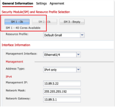
Figure 1: Security Module & Resource Profile Selection
In Figure 1, we can either create one 40 cores logical device or use those 40 cores to create multiple independent container instances.
Container instances have dedicated hardware assigned to them. This independence results in the following Multi-Instance solution benefits:
-
Hardware-level traffic processing isolation: Since each container instance has dedicated hardware allotted to it, one container instance cannot affect the performance of another container instance. Also, one tenant cannot access the traffic of another tenant running in a different container.
-
Hardware-level fault isolation: Each container runs software independently, meaning problems in one container instance only affect that container. The remaining container instances continue to run without issues.
-
Independent software version management: Each container is fully isolated at the hardware level and can run different FTD software versions in separate containers.
-
Independent upgrades and restarts: Each container is fully isolated at the hardware level, so FTD container instances can be independently upgraded and restarted without affecting other container instances.
-
Full management isolation: Each FTD container instance acts as a fully independent FTD firewall that can be managed independently either from the same Firewall Management Center FMC or different FMCs.
-
Full feature parity between a container and native instance(s): Every feature not dependent on specific hardware and supported in native instance mode is supported in container instance mode.
Multi-Instance Overview and Internals
Cisco Secure Firewall Threat Defense (FTD) release 6.3 added multi-instance support on 4100 and 9300 series appliances, release 7.4.1 added multi-instance support on 3100 series appliances, and release 7.6.0 adds multi-instance support on Secure Firewall 4200 series appliances. Using multi-instance, administrators can create and run multiple independent FTD software instances on the same hardware
appliance (Cisco Secure Firewall 3100 series, Cisco Firepower 4100 series, Cisco Secure Firewall 4200, and Cisco Firepower 9300 series appliances support Multi-Instance). Each FTD instance running on the hardware appliance has dedicated hardware resources to provide the benefit of guaranteed performance per instance and that one instance cannot affect the performance of another instance. This ensures meeting traffic processing isolation use case requirements. Also, multi-instance
ensures that the management plane for each instance is entirely independent of the other instances.
Instance creation relies on Cisco's Firepower Extensible Operating System (FXOS) to allow the administrator to create multiple FTD logical devices on the Firepower 4100 and 9300 series appliances running FXOS version 2.4 or higher. Provisioning FTD logical devices on 3100 and 4200 series appliances is provided through a single-management solution via Firewall Management Center FMC.
The logical device creation process remains the same as the previous FXOS software versions. What changes is that while creating an FTD logical device, the administrator chooses whether to create a "native instance" or a "container instance."
An FTD native instance is installed on the appliance(s) bare-metal hardware using all available resources. Therefore, customers migrating FTD logical devices from older FXOS versions will migrate to a native instance type of logical device. For appliances where Multi-Instance is supported, this is the default configuration.
On the other hand, a container instance doesn't consume all the available hardware resources on the appliance. Instead, it only consumes the hardware resources that the administrator specifies.
Note
To create multiple FTD logical devices on the hardware appliance, the first instance (and subsequent instances) needs to be the logical device type "container instance." The administrator creates a "Resource profile" beforehand that determines the number of hardware resources allocated to create the container instance.
When creating a container instance, FXOS running on the supervisor uses the FXOS agent running on the security module to generate a Docker container. Then FTD is installed inside this new Docker container.

Figure 2: Container Instance Creation
Note
Each Docker container has dedicated CPU, RAM, and hard disk that are not available to other FTD instances running in separate Docker containers on the same security module.
Secure Firewall 3100 & 4200 Series Multi-Instance Overview
The following table shows the minimum supported software and hardware platforms:
| Platform | FTD Version | Multi-Instance Support | Management Solution |
|---|---|---|---|
| 3105 | - | No | - |
| 3110 | 7.4.1+ | Yes | FMC |
| 3120 | 7.4.1+ | Yes | FMC |
| 3130 | 7.4.1+ | Yes | FMC |
| 3140 | 7.4.1+ | Yes | FMC |
| 4215 | 7.6.0 | Yes | FMC |
| 4225 | 7.6.0 | Yes | FMC |
| 4245 | 7.6.0 | Yes | FMC |
Table 1: Minimum Platform Support on Secure Firewall 3100 and Secure Firewall 4200
Historically, multi-instance has been a Firepower 4100 and Firepower 9300 capability using the on-box chassis manager for provisioning logical devices. For Secure Firewall 3100 series appliances on release 7.4.1 or higher and Secure Firewall 4200 series appliances on 7.6.0, multi-instance is provided through a single-management solution via FMC.
New in the 7.6 release, is the ability to convert the chassis (or device) from Native to Multi-Instance mode directly from FMC. During this process, the device will be unregistered and re-registered to the FMC automatically.
Observe below the configuration workflow, to utilize the Multi-Instance feature:
- Convert the device from Native to Multi-Instance mode in FMC.
- Create FTD instance(s) and assign interface(s).
- Optionally, update necessary interface changes and assign a Platform Settings Policy.
- Deploy configuration changes to device.
- FTD logical device is auto-registered to FMC. No manual step is required for registering logical device.
Important!
The Configuration Workflow below walks through a single Secure Firewall 4200 registered to a FMC. However, these exact steps can also be used on any Secure Firewall 3100 appliance that supports the Multi-instance Feature as long as FMC is on version 7.6.0.
Configuration Workflow
Convert Secure Firewall from Native to Multi-Instance Mode
-
Convert the device from Native to Multi-Instance mode in FMC by first logging in to FMC and navigating to Devices > Device Management.
-
Click the three-dots next to the chassis you would like to convert to Multi-Instance mode.
-
Click Convert to Multi-Instance.
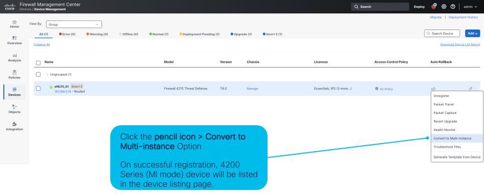
Figure 3: Device Management Page - Convert to Multi-Instance
-
-
A pop-up will appear in the FMC window noting that when converting from Native to Multi-Instance mode, chassis configurations will be reset. In addition, there is also a warning should you have modified the boot sequence, in that the chassis may end up in a Rommon state and a manual boot is required. Click Continue.
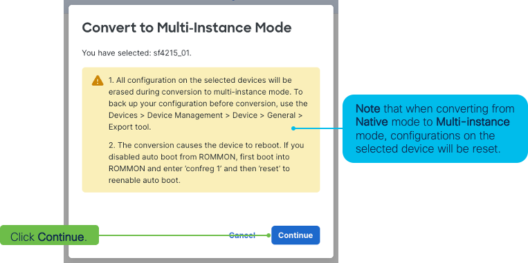
Figure 4: Configuration Reset Warning
-
Next, change the Configured device name using the textbox in the dialog box. For this example, "_MI_Manager" is appended to the device name. Then click Convert to Multi-Instance which will begin the conversion process of the chassis from Native to Multi-Instance mode.
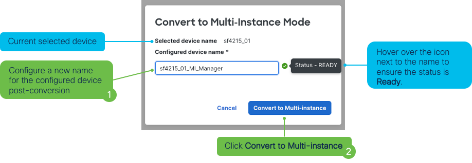
Figure 5: Rename Device
-
From here, track the progress of the conversion using the Message Center in FMC. During this process, the chassis will be unregistered and then automatically re-registered to FMC as a Multi-Instance Supervisor.
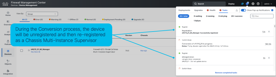
Figure 6: Message Center - Track Progress
-
Wait until the Conversion process has completed before moving to the next section. There will be a confirmation message inside the Message Center once the Chassis converts to Multi-Instance mode.
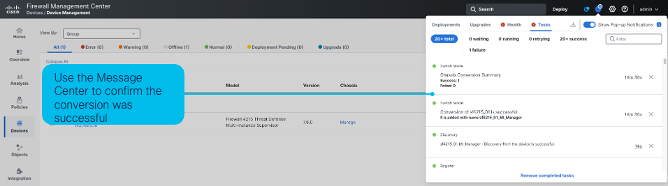
Figure 7: Message Center - Successful Conversion
-
Under Devices > Device Management, confirm that the Chassis is listed as a "Multi-Instance Supervisor".
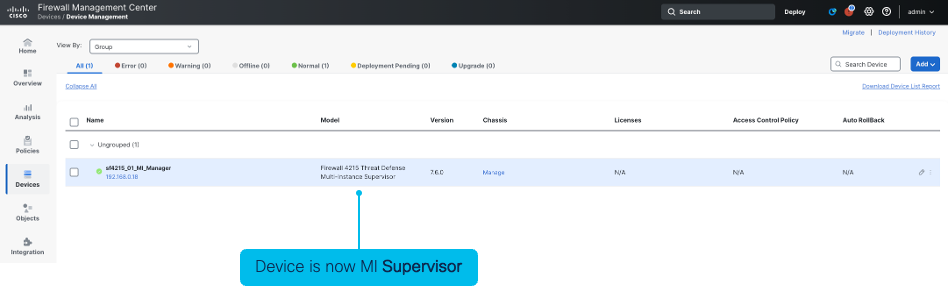
Figure 8: Device Management Page - Multi-Instance Supervisor
Firewall Threat Defense Management for Secure Firewall 3100 & Secure Firewall 4200
Now that the Secure Firewall Chassis is in Multi-Instance mode, the next step is to create Firewall Threat Defense (FTD) instances on the chassis. Click the Manage link in the Device Management page to get started.
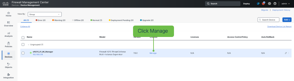
Figure 9: Chassis - Manage Link
-
Under the Multi-Instance Chassis Summary page, there is information regarding device, interface, and hardware status. Under the various tabs you can find specific configuration for interfaces, instances, and system configuration
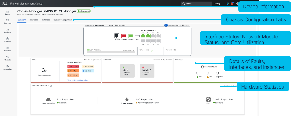
Figure 10: Chassis Summary Tab
-
Head over to the Instances tab. Click Instances > Add Instance. (Or, Add an instance. This link appears when there are not an existing configuration.) This launches the FTD Instance Creation Wizard.
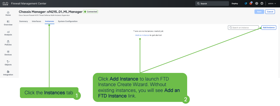
Figure 11: Chassis Instances Tab
-
Read and accept the EULA in the pop-up. Click the check-box and then click Next.
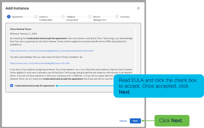
Figure 12: Instance Creation Wizard - EULA
-
Configure the Instance by adding configuration details in the Instance Configuration menu.
-
In the Display Name box, enter a name specific to the FTD Instance.
-
In the Resource profile drop-down, choose from three of the pre-defined profiles. Or, the plus icon allows definition of customer resource profiles. However, keep in mind that over-subscription of the Chassis is not supported. In this example, the Default-Small profile is configured.
-
In this example, only IPv4 is configured and used. However, there are options to configure only-IPv6 or Both IPv4 and IPv6. Configure the Management IP, Network Mask, and Network Gateway based on the Chassis environment.
-
Populate the remainder of the required parameters like, Device SSH Password and Firewall Mode. Optionally, configure Search Domain, FQDN, and DNS Servers.
-
Click Next.
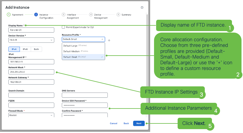
Figure 13: Instance Creation Wizard - Configuration
-
-
Under the Interface Assignment menu, add Available Interfaces to the Selected Interfaces column using either the + or the >> icons for individual or multiple interfaces, respectively. For this example, Ethernet1/1 and Ethernet 1/2 are assigned to this FTD Instance.
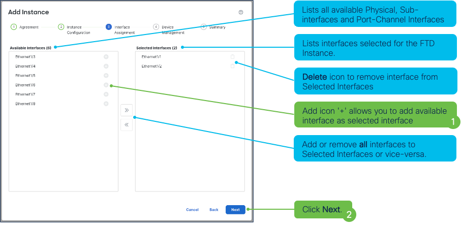
Figure 12: Instance Creation Wizard - Interface Assignment
-
In the Device Assignment menu is where Device Group (Optional), Access Control Policy, Platform Settings Policy (Optional), and Smart Licensing can be assigned to the FTD Instance. Fill in the necessary settings and click Next.
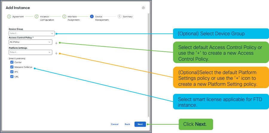
Figure 13: Instance Creation Wizard - Device Management
-
Review configurations. Under the Summary menu you will find the details for the Instance Configuration, Device Management, and Interface Assignment. In this menu, administrators have the ability to change the specific configurations before saving. The respective pencil icon allows editing of the configuration. Click Save.
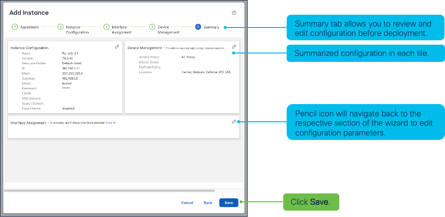
Figure 14: Instance Creation Wizard - Summary
-
This will bring you back to the Instances tab. Click Save once more and now this configuration needs to be applied to the Chassis.
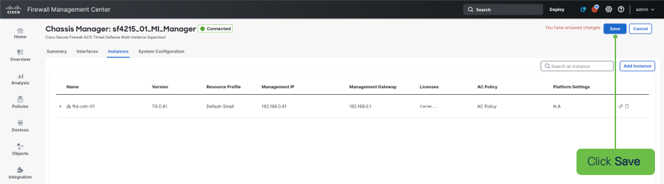
Figure 15: Chassis Instances Tab
-
Apply configurations by first clicking Deploy. Click the check-box next to the device, then click Deploy.
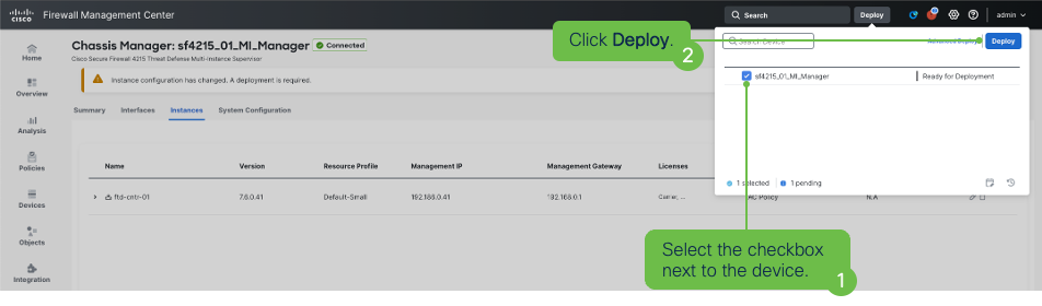
Figure 16: Deployment Menu
-
Upon successful deployment, the logical FTD instance will boot and once online is auto-registered with FMC. The newly provisioned logical instance can be seen in the Device Management page under Device > Device Management.

Figure 17: Device Management Page
Interface Options for Firewall Threat Defense Instances
The following figure provides an overview of interface options available for provisioned FTD instances on Secure Firewall devices that support the Multi-Instance feature:
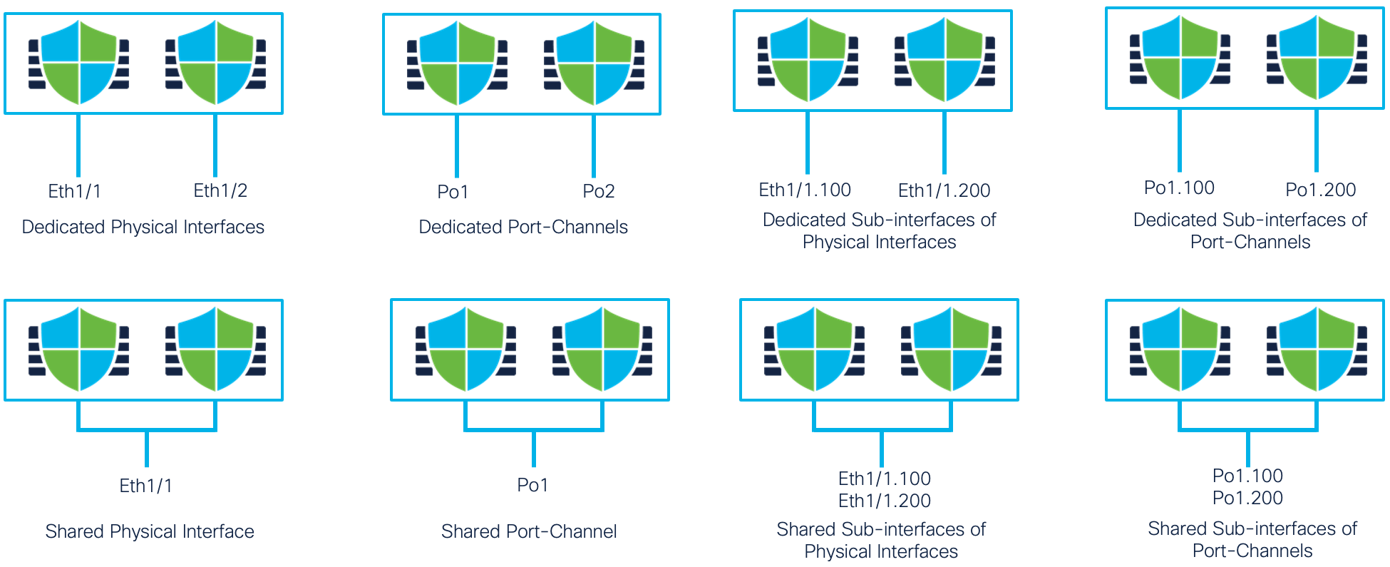
Figure 18: Available Interfaces for FTD Instances
Hardware Resources not Supported in a Docker Container
In Release 6.3, the hardware resources distributed among FTD instances are CPU, RAM, and hard disk. No other hardware resources such as Flow Offload (used for hardware trusted traffic acceleration) and Crypto (used for improving encryption and decryption performance by offloading these operations to dedicated hardware) are allotted FTD instances. Also, no hardware-based features such as TLS offload and Flow offload are available on container instances. In Release 6.4, one instance can use the hardware crypto resources. For Firepower 4100 and 9300 series devices release 6.6 and above, up to 16 instances can use the hardware crypto resources (split according to the percentage of CPUs assigned to the instance).
Network interfaces are another hardware resource that container instances need. With the creation of multiple FTD logical devices on the same security module and only a limited number of interfaces available on the appliance, FXOS now allows interface sharing between logical devices and the creation of sub-interfaces on FXOS allottable to the logical devices.
Factors Limiting Instances Creation on an Appliance
The maximum number of instances created is determined by the hardware resources available because each container instance requires dedicated hardware resources assignment.
Note
Instances primarily use dedicated hardware resources from the security module, but there are cases where they may need resources from the supervisor.
Supervisor Hardware Resources Distribution
Supervisor module resources contribute to limiting the number of possible container instances because some of the module’s hardware resources are consumed for each container instance generated. Since all traffic to the security module comes through the hardware switch available on the supervisor, the availability of these two hardware resources (listed below) becomes a deciding factor for the maximum number of interfaces and instances on an appliance:
- Switch Forwarding Path entries available on the hardware switch
- Ingress VLAN group entry counts
The supervisor’s hardware switch has a fixed number of Switch Forwarding path entries available to program the path from physical interfaces available on the supervisor to logical interfaces on specific container instances. Typically, a maximum of 1021 switch forwarding path entries are available on all appliances. A few of these entries are consumed to create a path between a physical interface and a non-shared logical interface assigned to an instance. In other words, you have a limited number of non-shared interfaces available for allotment to the instances.
Additionally, the number of switch forwarding path entries becomes more critical when sharing interfaces between instances. In that case, inter-instance traffic flows through the shared interfaces via the hardware switch on the supervisor. For this, the supervisor needs to program a path between every instance pair using every pair of shared interfaces, which exponentially increases the switch forwarding path entry consumption and limits the number of possible instances. The latter half of this document explains more details on using interfaces and subinterfaces.
Also, the Ingress VLAN group entry count has the potential to restrict the maximum number of VLAN sub-interfaces created on the supervisor, which may limit the number of instances created overall. The VLAN group entry table tracks ingress VLAN IDs on the sub-interfaces configured on a physical interface on the supervisor. The maximum number is 500 entries, and at least one entry from this table is consumed for every VLAN sub-interface created.
Note
The Firepower 9300 series appliances supervisor hardware-based limits apply for the cumulative number of instances created across all three security modules on the chassis.
Security Module Hardware Resources Distribution
Docker container(s) creation occurs on the security module. The hardware resources available on the security module are then allocated independently amongst the various container instances. The hardware resources are:
- CPU cores
- RAM
- Disk space
Since each of these resources are available in limited quantities on the security module, the number or amount of these resources dictates the maximum number of possible instances on the security module.
Disk Space as the Limiting Factor
An instance is allotted 48GB of dedicated disk space regardless of its size. This way, if there are a sufficient number of CPUs and enough RAM, the maximum number of instances possible would be <DISK_SIZE>/48,
where:
- DISK_SIZE is the size of the hard disk on the security module available for allotment
- 48GB is the disk space consumed for each instance, FXOS infrastructure, host operating system, and the Docker runtime environment on Firepower 4100 and 9300 series.
- 40GB is the disk space consumed for each instance on Secure Firewall 3100 and 4200 series.
Resource Profile Instance Sizing
The administrator is responsible for identifying the distribution ratio and security module hardware resources assigned to an instance, which determines the instance's overall size. The administrator uses the Resource Profile to allocate hardware resources when creating an instance.
The Resource Profile specifies the instance:
- The number of logical CPU cores
- The amount of RAM (depends upon the number of CPUs assigned to the instance)
The ratio of the security module's total number of logical CPU cores available to the logical CPU cores assigned to an instance, is proportional to the security module's available RAM to the amount of RAM assigned to the instance. Therefore, the resource profile controls the size of an instance. To illustrate, for a security module with 18 CPU cores and 120MB of RAM, creating an instance that consumes six logical CPU cores, would consume 40MB of RAM (6/18 = 1/3, 1/3 x 120MB = 40MB).
Resource Profile Limits
The resource profile defines an instance's number of logical CPU cores as described above. However, there are some restrictions for choosing a valid resource profile value:
- The security module requires a minimum of two logical CPU cores for FXOS. In other words, the security module’s total number of application CPU cores available for allotment to instances is two logical CPU cores less than the available logical CPU cores.
- The maximum value selectable in the resource profile for the number of CPUs assignable to an instance is the total number of application CPU cores available on the security module.
- An even number of CPU cores must be assigned to an instance.
- Instances require a minimum of six logical CPU cores (two Mgmt, two data plane, two Snort)
- FXOS 2.7.1 and higher allows creating a resource profile with eight logical CPU cores.
Maximum Possible Instances on a Security Module
Based on the information above, the main factors deciding the maximum number of possible instances on a security module are:
- The logical CPU cores available
- The hard disk size
- The possible number of supervisor interfaces
- A combination of the number of shared interfaces and the number of instances sharing those interfaces
By omitting the last two factors above and focusing only on the logical CPU cores and hard disk space, the maximum number of possible security module instances is easily calculated based on these two factors:
- Total CPU cores divided by at least six cores per instance
- Total Disk space divided by 48GB (required disk space per instance)
The following table shows the maximum number of instances possible on the Secure Firewall 3100, Firepower 4100, and Firepower 9300 series platforms:
| Platform | Maximum FTD Instances |
|---|---|
| Secure Firewall 3110 | 3 |
| Secure Firewall 3120 | 5 |
| Secure Firewall 3130 | 7 |
| Secure Firewall 3140 | 10 |
| Firepower 4112 | 3 |
| Firepower 4115 | 7 |
| Firepower 4125 | 10 |
| Firepower 4145 | 14 |
| Firepower 4110 | 3 |
| Firepower 4120 | 3 |
| Firepower 4140 | 7 |
| Firepower 4150 | 7 |
| Secure Firewall 4215 | 10 |
| Secure Firewall 4225 | 15 |
| Secure Firewall 4245 | 34 |
| Firepower 9300 SM-40 | 13 |
| Firepower 9300 SM-48 | 15 |
| Firepower 9300 SM-56 | 18 |
| Firepower 9300 SM-24 | 7 |
| Firepower 9300 SM-36 | 11 |
| Firepower 9300 SM-44 | 14 |
Table 2: – Maximum FTD Instances
Factors Affecting Container Instance Performance
The previous section discussed the factors determining the possible number of FTD instances on an appliance. Now, let’s consider the factors that affect FTD instance performance.
Disabled Hardware Acceleration Support
One of the first and more obvious factors that affect specific flow type performance is the lack of support for hardware acceleration within the container instances in Release 6.3. Two hardware acceleration components
are available on the Firepower 4100 and 9300 series appliances:
- The Crypto Engine provides encryption and decryption acceleration to support TLS/IPsec VPN and TLS traffic inspection at scale. Container instances can use hardware crypto acceleration in Release 6.4 (one instance only can use the hardware crypto), and Release 6.6 and above (up to 16 instances can share the hardware crypto). However, in Release 6.3, the hardware crypto acceleration is unassignable to a container instance and is not distributable between container instances. The lack of access to the hardware crypto engine impacts performance of any instance requiring crypto.
- The Hardware Flow Offload Engine helps provide very high throughput and extremely low latencies for elephant flows.
Note
The absence of these hardware components in container instances causes a noticeable reduction in the elephant flow maximum performance compared to running FTD in native mode until instance hardware offload is added in a future release.
Inter-Instance Communications
If instances use shared interfaces, communication happens through the hardware switch on the supervisor module, reducing the need for traffic to leave the appliance and be forwarded back into it externally. However, it does add to the backplane traffic flows.
Note
The backplane connecting a security module to the supervisor on all Firepower 4100 and 9300 series appliances consists of 2x40Gig interfaces with an 80Gbp maximum data transfer capacity between the
supervisor and security module (except for the 4110 where the backplane is 1x40Gig interface). This means that all the instances created on the security module share this bandwidth to process traffic coming in and out of the instances from outside the box and process traffic flowing between instances that don't need to leave the appliance.
Docker Containers Performance Overhead
Each independent FTD instance runs within a Docker container. It is well-known that the performance of an application running as a container is almost identical to the same application running natively on bare metal (several independent tests validate this fact, and several published white papers explain this in detail). Internal test results match the external observations.
Note
Smaller individual instance performance depends on the number of CPU cores assigned. Among the CPU cores allotted to the instance, two CPU cores are assigned for management processes, with the rest divided among data plane threads and Snort processes in a ratio between 1:2 to 1:1.
Cost of Independent Instances
Multi-instance aims to provide complete independence between instances to ensure that no container instance affects another under any circumstances. Also, this requires that management applications such as the Firewall Management Center (FMC), and SSH connections to the CLI are fully independent and able to reach the container instance even if other instances are overloaded or down. For this, as mentioned in the previous section, two CPU cores for every instance are dedicated to running management processes to guarantee independent and predictable instance manageability.
However, the cost of independent and predictable instance manageability, the CPU core allocation for management, every core that is not running a data plane thread or a Snort process effectively reduces the total
appliance traffic processing performance.
So, although the single container instance performance consuming all the security module hardware resources is equal to a native instance, the same is not true as the number of instances increases. To illustrate, if
a native FTD instance has 10Gbps throughput hypothetically, 10Gbs is the expected container instance throughput when allocating all the hardware resources to that single container instance.
Conversely, creating three container instances on the same hardware share hardware resources cannot achieve the cumulative 10Gbp throughput because the total CPU cores assigned to management processes for three
container instances are six CPU cores compared to only two CPU cores in the case of a single instance. Given the four additional CPU cores are not used for traffic processing reduces the overall throughput of the
appliance. As the instance number increases, the overall throughput decreases because each instance requires two management process CPU cores.
Estimating Instance Performance
While creating an instance, it is essential to estimate the performance obtainable from the instance correctly. When discussing firewall performance, the three main values include firewall:
- Throughput
- Maximum concurrent connections
- Maximum connections per second
To calculate these performance values for instance sizing, the formulas use the following variables:
- <MAX_CPU> - represents the total number of logical CPU cores available on a particular hardware platform
- <RE_PROFILE> - represents the number of logical CPU cores selected in the resource profile associated with the container instance
- <MAX_CON_CONN> - represents the maximum number of connections supported on the platform when FTD is installed as a native instance (obtainable from the datasheets)
- <MAX_THRU> - represents the maximum throughput of a specific appliance when FTD is installed in native mode (obtainable from the datasheets)
AMP’s Small Instance Impact
Before estimating container instance throughput, it is essential to determine the features enabled by the customer. For example, if a customer is enabling AMP, the small six core and eight core instances are unsuitable. Appendix 1 shows the core distribution for all devices supporting multi-instance. For a six core instance, two cores are assigned to Snort. When enabling AMP in a 6 core instance, one Snort core is consumed by AMP, reducing the IPS throughput. In a six core instance sharing the same physical core, there is a 15-20 percent
performance impact.
Similarly, when considering an eight core instance, the impact is higher as AMP consumes two out of the four cores typically assigned to Snort. As AMP consumes a maximum of two cores, instances with 10 cores or more do not experience as much of a performance impact.
Estimating Container Instance Throughput
Before heading into the calculations, let us review the devices core distribution:

Figure 19: Devices Core Distribution
As shown in Figure 3 above, an SM 56 security module has 110 total cores. For one security module, the maximum throughput stated on Release 7.0 datasheet for FW+IPS(AV+IPS) packet size 1024B is 68Gbps. The cores are spread across the system, SSP Operating system, data plane and Snort. The distribution of the cores between the data plane and Snort is uneven, with more cores assigned to Snort for resource-intensive deep packet inspection. Also, Image 3 shows that the Snort per core throughput and the data plane differ.

Figure 20: Traffic Flow
As the traffic passes the data plane before heading to Snort for deep inspection, it is important to identify if the data plane or Snort is the limiting factor for generating the maximum throughput. If the data plane can’t process enough traffic, irrespective of how many extra cores you assign to Snort, the data plane will limit the maximum throughput.
A data plane limitation example:

Figure 21: Data Plane Limitation
When creating an eight core instance in an SM 56, two cores are allocated to the data plane and four cores to Snort. The native core distribution is listed in Appendix 1/Table 1. As we can see that the incoming traffic from the data plane is lower than the Snort, irrespective of how much more Snort can process, the maximum
throughput will be decided here by the data plane, which in our case here is 3.08 Gbps.
A ten core instance example:

Figure 22: Ten Core Instance
Similarly, for a ten core instance in an SM 56, four cores are allocated to the data plane and four cores to the Snort. In Image 6, Snort can inspect a maximum 4.24 Gbps, which limits the maximum traffic irrespective of the additional traffic the data plane sends to Snort. Snort is the limiting factor in a ten core instance, with a maximum throughput of 4.24 Gbps.
With the data plane or Snort limiting factor in mind, let's now calculate the maximum throughput based on the cores allocated to a given instance. Calculating the maximum throughput of an FTD instance requires two main steps.
-
Calculate Per core device throughput - Both data plane and Snort individually (Refer to Image 3)
- Refer to the Secure Firewall datasheet for the published FTD throughput numbers.
- Identify the number of native cores for the data plane and Snort from Table 2.
- As shown in Image 4, calculate the per-core throughput for both the data plane and Snort for a device by dividing the “Maximum datasheet throughput / Number of native cores (data plane and Snort separately).”
-
Calculate for X size instance throughput based on core allocations (Refer to Image 5 and Image 6)
- After calculating the per core throughout for the data plane and Snort, refer to Appendix 1 for the core allocation of a given instance of size X, X being the value from six (Small) to the maximum allowed by the device.
- Calculate based on the core allocation the total data plane and Snort throughput for X instance as shown in Images 5 and 6.
- Determine if the limiting factor is the data plane or Snort throughput, the lower of the two as explained in Images 5 and 6.
Note
The "show asp inspect-dp snort" command provides the number of Snort processes running.
Use the formula below to calculate the maximum container instance throughputs for the data plane and Snort. The lower throughput of the two determines the limiting factor.
Maximum Data plane core throughput, for instance size X
Data Plane Maximum throughput*=
(< Max_ Datasheet_Throughput > / < Data_Plane_Core_Count >) * < Data_Plane_Cores_Allocated_to_X >
Where:
• < Max_ Datasheet_Throughput > is the datasheet throughput, use either “FW+AVC” or “FW+AVC+IPS”
• < Data_Plane_Core_Count > is the number of logical CPU cores running data plane on a native FTD instance (obtainable from Table 2).
Maximum Snort core throughput, for instance size X
Snort Based Maximum throughput*=
(< Max_ Datasheet_Throughput > / < Snort_Core_Count>) * <Snort_Cores_Allocated_to_X >
Where:
• < Max_ Datasheet_Throughput > is the datasheet throughput, use either “FW+AVC” or “FW+AVC+IPS”
• < Snort_Core_Count > is the number of logical CPU cores running Snort on a native FTD instance (obtainable from Table 2).
Let us take two quick examples to learn the correct implementation of these formulae.
Examples of Calculating the Instance Throughput
Example 1
Calculating the “Firewall + AVC + IPS” instance throughput with a resource profile value of 20 running on a Firepower 4145.
Calculate the Snort core throughput:
Maximum Snort throughput * ( 1024B) =
(< Max_ Datasheet_Throughput > / < Snort_Core_Count>) * <Snort_Cores_Allocated_to_X >
< Max_ Datasheet_Throughput > = 53 Gbps (FW+AVC datasheet throughput)
< Snort_Core_Count> = 52 total Snort cores for logical/native device (obtained from Table 2)
< Snort_Cores_Allocated_To_X> = 10 Snort cores (obtained from Appendix 1 for instance size 20)
Maximum Snort throughput = (53/52)*10 = 10.19 Gbps
Calculate the Data Plane core throughput:
Maximum Data Plane throughput * (1024B)=
(< Max_ Datasheet_Throughput > / < Data_Plane_Core_Count >) * < Data_Plane_Cores_Allocated_to_X >
< Max_ Datasheet_Throughput > = 53 Gbps (FW+AVC datasheet throughput)
< Data_Plane_Core_Count > = 32 data plane cores for logical/native device (obtained from Table 2)
< Data_Plane_Cores_Allocated to X > = 8 data plane cores (obtained from Appendix 1 for instance size 20)
Maximum Data Plane throughput = (53/32)*8 = 13.25 Gbps
Final Result = Select the lowest throughput of the two, which for this example is Snort.
Snort Maximum throughput = (53/52)*10 = 10.19 Gbps
Data Plane Maximum throughput = (53/32)*8 = 13.25 Gbps
Example 2
Calculating the “Firewall + AVC + IPS” instance throughput with a resource profile value of 18 running on a Firepower 4145.
Calculate the Snort core throughput:
Maximum Snort throughput * (1024B)=
(< Max_ Datasheet_Throughput > / < Snort_Core_Count>) * <Snort_Cores_Allocated_to_X >
< Max_ Datasheet_Throughput > = 53 Gbps (FW+AVC datasheet throughput)
< Data_Plane_Core_Count > = 52 data plane cores for logical/native device (obtained from Table 2)
< Data_Plane_Cores_Allocated to X > = 8 data plane cores (obtained from Appendix 1 for instance size 20)
Maximum Snort throughput = (53/52)*10 = 10.19 Gbps
Calculate the Data Plane core throughput:
Maximum Data Plane throughput * (1024B)=
(< Max_ Datasheet_Throughput > / < Data_Plane_Core_Count >) * < Data_Plane_Cores_Allocated_to_X >
< Max_ Datasheet_Throughput > = 53 Gbps (FW+AVC datasheet throughput)
< Data_Plane_Core_Count > = 32 data plane cores for logical/native device (obtained from Table 2)
< Data_Plane_Cores_Allocated to X > = 6 data plane cores (obtained from Appendix 1 for instance size 20)
Maximum Data Plane Throughput = (53/32)*6 = 9.94 Gbps
Final Result = Select the lowest throughput of the two, which for this example is the data plane.
Snort Maximum throughput = (53/52)*10 = 10.19 Gbps
Data Plane Maximum throughput = (53/32)*8 = 9.94 Gbps
Note
As you can see in the examples, the Snort cores were the same for both instance sizes (18 and 20 for a Firepower 4145), but the data plane cores were different. That exemplifies why it is crucial to determine whether Snort or the data plan sets throughput limit.

Table 3:– (4145) 18 vs 20 Resource size comparison using the same Snort core count
The following tables provide the maximum throughput (Firewall + AVC + IPS: 1024B) for three use cases for the 9300 and 4100 series appliances. The three cases covered are:
- Small - Smallest instance size possible on the security module
- Medium- An instance using half of the resources
- Maximum – One container instance consuming all resources
Note
The first column of the table below shows only the total Snort cores assigned from the native logical device core allocation. Remember, the total logical cores are split across Snort, data plane, management, and FXOS.
| Platform Native (Snort Core Assigned) | Max throughput of the small instance (Instance size 6 Cores which has 2 Snort Cores) |
Max throughput of the medium instance (Cores) | Max throughput of the Maximum instance (Cores) |
|---|---|---|---|
| Firepower 4112 (12) | 3.2 Gbps | 12.7 Gbps (14) | 19 Gbps (22) |
| Firepower 4115 (28) | 2.36 Gbps | 18.9 Gbps (26) | 33 Gbps (46) |
| Firepower 4125 (36) | 2.5 Gbps | 22.5 Gbps (32) | 45 Gbps (62) |
| Firepower 4145 (52) | 2.04 Gbps | 28.53 Gbps (46) | 53 Gbps (86) |
| Firepower 4110 (12) | 2.6 Gbps | 10.3 Gbps (14) | 15.5 Gbps (22) |
| Firepower 4120 (24) | 2.3 Gbps | 16 Gbps (26) | 27.5 Gbps (46) |
| Firepower 4140 (36) | 2.4 Gbps | 22 Gbps (36) | 44 Gbps (70) |
| Firepower 4150 (48) | 2.2 Gbps | 28.7 Gbps (46) | 53 Gbps (86) |
| Firepower 9300 SM-40 (44) | 2.5 Gbps | 30 Gbps (42) | 55 Gbps (78) |
| Firepower 9300 SM-48 (52) | 2.5 Gbps | 35 Gbps (50) | 65 Gbps (94) |
| Firepower 9300 SM-56 (64) | 2.1 Gbps | 36.1 Gbps (58) | 68 Gbps (110) |
| Firepower 9300 SM-24 (24) | 2.7 Gbps | 19 Gbps (26) | 32.5 Gbps (46) |
| Firepower 9300 SM-36 (36) | 2.6 Gbps | 23 Gbps (36) | 46 Gbps (70) |
| Firepower 9300 SM-44 (44) | 2.8 Gbps | 36 Gbps (46) | 67 Gbps (86) |
Table 4:– Firewall | AVC | IPS: 1024B throughput based on the FTD 7.0 – Snort 3 datasheet
Instance size selection for optimal performance:
A 4110 has a total of 22 cores. For a user wanting 3 instances using the six core instance size, the total core consumption is 6*3 = 18 cores, leaving four unused cores (22-18 = 4). To fully utilize all the available cores create two 8 core instances size and one 6 core instance (8*2 + 6*1 = 22)
Estimating an Instance’s Maximum Concurrent Connections
Estimating the maximum concurrent connections for a specific instance is straightforward because this value depends on the RAM allocated to the container instance.
The following formula provides the maximum concurrent sessions for a container instance:
Maximum concurrent sessions = (<RE_PROFILE> * <MAX_CON_CONN>) / <MAX_CPU>
- RE_PROFILE is the total cores for the selected instance size
- MAX_CON_CONN are listed in the datasheet
- MAX_CPU is the native instance CPU total (a 4110 has 22 CPUs as listed in Table 2)
Multi-Instance Recommendations
Based on the multi-instance solution architecture, there are some frequently asked questions and recommendations for getting the most out of container instances.
Do I Create a Native Instance or Container Instance?
This decision depends entirely on the probability of needing more instances in the future. If you expect to have more than one instance on the same security module in the future, then it might be easier to start
with one container instance consuming all the hardware resources. If at a later point you need to create another instance, the resource profile associated with the existing container instance can be changed to allot fewer CPU cores to free up resources to add more container instances.
Note
Resizing a container instance requires rebooting FTD which may lead to temporary traffic outages. but can be avoided by configuring instance-level high availability. Also, when decreasing the size of an instance, the policies may not fit in the new smaller RAM after a reboot.
Suppose you are positive that you will never have multiple instances running on the same security module. In that case, it is recommended to run FTD as a native instance to take advantage of the hardware acceleration capabilities, like flow offload and hardware TLS decryption.
FMC or FXOS Sub-Interface Creation?
With the multi-instance solution, an administrator can assign physical interfaces to a container instance and create sub-interfaces or VLAN interfaces in the FMC. Alternatively, one can create sub-interfaces or VLAN interfaces on FXOS and assign the sub-interfaces to container instances.
For more on optimizing the interface and sub-interface usage, please refer to this article, Using Multi-Instance Capability.
Assigning the physical interface to a container instance and creating sub-interfaces from the FMC is preferred to reduce forwarding table issues. Furthermore, doing so avoids hitting the ingress VLAN Group table entries limit or the supervisor's switch forwarding path entries table limits.
When creating sub-interfaces shared across instances or assigning them as dedicated interfaces to different container instances, the only option is to create sub-interfaces in FXOS.
Shared Interface Recommendations
The general recommendation is to limit the interfaces shared between multiple container instances. However, sharing an interface often becomes necessary in many real-world scenarios.
If your needs dictate sharing an interface across several instances, the preference is to share a sub-interface rather than a physical interface. Additionally, for the best scalability, sharing sub-interfaces from a single parent is recommended rather than sharing sub-interfaces from different parent interfaces.
Sharing a Failover/Stateful Interface for Inter-Instance HA Configuration
High availability (HA) configuration is supported between instances, and firewalls are rarely deployed in production networks without HA (HA might be optional if deploying FTD in intrusion prevention mode).
If several instances exist on the same appliance, and each instance HA pair requires a dedicated logical interface as its HA link and state link, assigning a physical interface to each pair is impractical and sometimes not possible.
Note
It is recommended to create a port-channel interface with two physical member interfaces for redundancy and create one pair of VLAN sub-interfaces for each HA pair.
The figure below shows supported standalone and high-availability configurations for logical instances. Each instance can either act as its own separate context with its various resource constraints, or the alternative is having these instance in a high-availability pair. The caveat is that the primary and the secondary units of the HA pair cannot be on the same physical chassis.
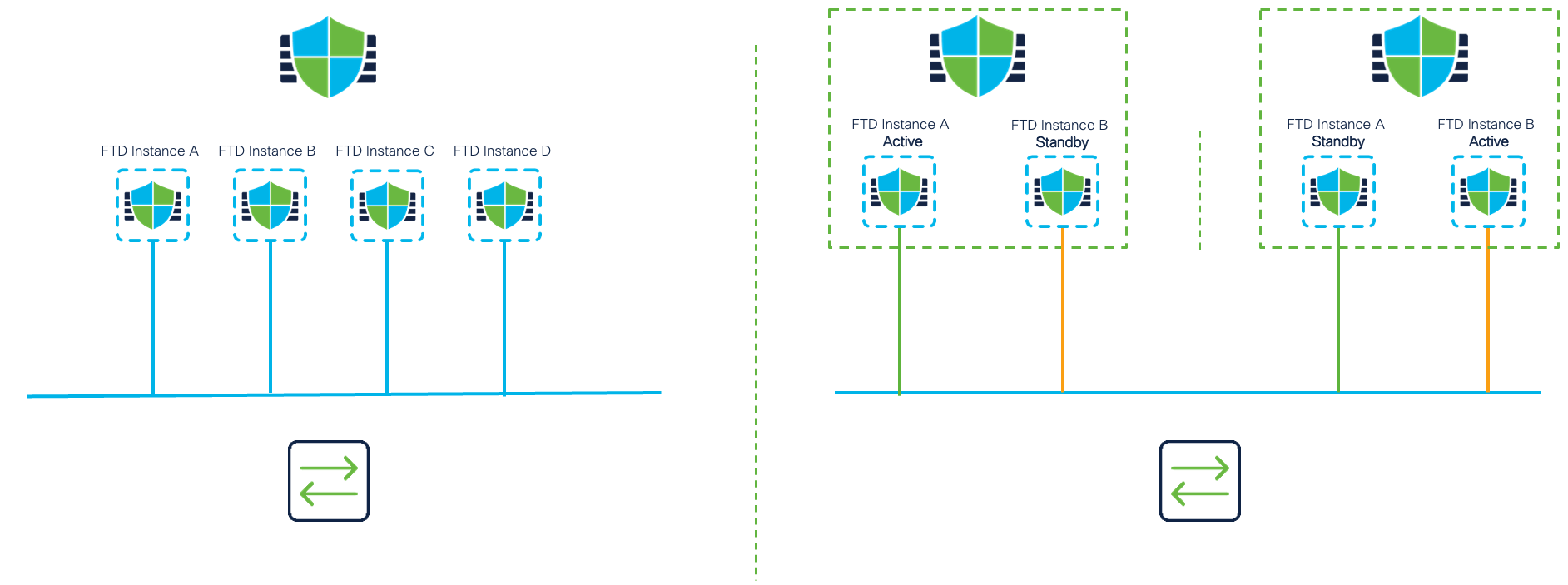
Figure 23: Supported Standalone or High-Availability Configurations
Valid Resource Profile Values
Theoretically, all resource profile sizes (from 6 to the maximum CPU count for the hardware) are valid if they adhere to the validity rules mentioned in the Resource Profiles section. But, as discussed above, the expectation when creating a container instance is that at least two container instances be created on the security module. With that condition in mind, any resource profile value that does not leave enough CPU cores to create another instance becomes logically invalid. Also, it is best not to leave CPU cores unassigned.
Updated about 1 year ago