
Virtual Firewall Clustering
Cisco Secure Firewall virtual firewall clustering in public and private cloud
Introduction
A key enhancement for Cisco Secure Firewall, introduced in Release 7.2, is support for clustering Cisco Secure Firewall Threat Defense virtual (FTDv). The 7.3 release extended Cisco Secure Firewall to Azure. The following YouTube video provides a demonstration of FTD public cloud and private cloud clustering.
️ Note
The 9.17.1 release introduced Cisco Secure Firewall ASA (ASA) private cloud clustering. Public cloud ASAs cannot be clustered. The 9.19.1 extended ASA clustering to AWS.
ASA clusters configuration is the same as FTD cluster data plane configuration. For simplicity, this document does not cover ASA clustering.
See the reference section below for information.
How Cisco Secure firewall implements VXLAN and GENEVE technology is central to this document. Therefore, understanding the content of VXLAN and GENEVE Support is a highly recommended prerequisite.
Clustering Support
Supported Platforms and Licensing
All nodes and the Firewall Management Center must be running 7.2 or above. For Azure, all nodes must be running 7.3 or above.
- Azure, AWS, and GCP support FTD clusters with up to 16 nodes.
- VMware and KVM support FTD clusters with up to 4 nodes.
This feature requires no additional licensing.
Limitations
- Clustering does not support autoscale.
- Clustering does not support CDO or FDM management.
- Physical FTD clusters do not support certain features. These limitations extend to virtual FTD clusters. See the reference section at the end of this document.
Basic Clustering Concepts – Physical or Virtual
Clustering allows multiple Cisco Secure Firewalls to function as a single logical firewall.
Before focusing on virtual firewalls, we discuss key concepts and terminology that apply to both physical and virtual firewalls.
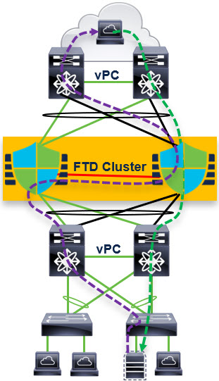
Figure 1. FTD Cluster
Cluster node roles:
- Control Node – synchronizes cluster configuration
- Flow Owner (nondeterministic) – receiver of the first packet of a flow
- Flow Director (deterministic) – keeps track of the flow owner
Cluster Control Link (CCL) for internode communication:
- Connection state sharing
- Node discovery and health check
- Asymmetric traffic redirection to the flow owner
As an example of cluster operation, let us focus on TCP traffic. UDP and ICMP traffic are similar.
- If a node receives the SYN packet of a flow, it notifies the flow director that it is now the flow owner of this flow.
- If a node receives a packet that is not a SYN packet and does not belong to a flow it owns, it will query the flow director.
- The flow director responds with the location of the flow owner (if there is one). In this case, the node forwards the packet through the CCL to the flow owner.
- If the flow director responds that there is no flow owner, the node drops the packet.
️ Warning
Cluster nodes share connection state. The cluster stores two copies of each connection state on separate nodes to provides redundancy in case a node fails.
Cluster nodes do not share IPS state. A cluster node failure during an attack could therefore create a false negative, but it is extremely unlikely.
Porting Clustering to the Cloud
Cisco modified the cluster implementation to adapt clustering technology to the cloud.
| Physical FTD Cluster | Virtual FTD Cluster |
|---|---|
| Data interfaces have two modes: Individual interface mode – different nodes have different IP addresses on data interfaces. Spanned interface mode – all nodes share a VIP for each data interface. Spanned interface mode is far more common. It uses EtherChannel for load balancing traffic coming to and from the switching infrastructure. | The cluster only uses individual interface mode. You will need a layer 3 (or higher) load balancer load balances the traffic. |
| The CCL uses a proprietary protocol encapsulated in IP. * | The CCL link uses VXLAN over UDP. * |
| Cisco recommends increasing the MTU of the CCL by 100 bytes to accommodate the cluster metadata header. ** | Cisco recommends increasing the MTU of the CCL by 150 bytes to accommodate the cluster metadata header and the VXLAN header. ** |
| The CCL uses multicast to discover and monitor cluster nodes. This allows dynamic node discovery. | The CCL uses unicast to discover and monitor cluster nodes. This requires a static list of candidate peer IP addresses, called a peer group. |
* Public cloud infrastructures require layer 4 headers to function properly.
** Cluster nodes forward encapsulated frames of the asymmetric traffic across the CCL. Increasing the MTU avoids CCL traffic fragmentation.
Cluster Configuration
The primary difference between public and private cloud cluster configuration is the role of the FMC.
| Public Cloud (Azure, AWS, and GCP) | Private Cloud (VMware and KVM) |
|---|---|
| Do not use the FMC for initial cluster configuration. | Use the FMC for initial cluster configuration. |
| Use day-0 configuration to bootstrap the cluster. | You do not need to use any day-0 configuration to bootstrap the cluster. |
| You must register a single cluster node to the FMC. | You must register each cluster node separately to the FMC. |
| The FMC discovers the cluster and automatically registers the remaining nodes. * | Once you register all the nodes, you create the cluster using the FMC. |
| Use the FMC for remaining configuration. | Use the FMC for remaining configuration. |
* This is auto-registration. You will also see this in certain recovery scenarios with private cloud clustering.
️ Note
For those familiar with physical device clustering, the following may help.
- Public cloud cluster configuration is analogous to clustering FPR 4100 series or FPR9300 devices running FTD. The day-0 configuration takes the place of the FXOS configuration.
- Private cloud cluster configuration is analogous to clustering FPR3100 series devices running FTD. You build the 3100 cluster using the FMC.
Public Cloud (Azure, AWS, and GCP) Configuration
You need to create the cluster prior to FTD node registration to the FMC using a day-0 configuration.
- Azure refers to day-0 configuration as either custom data or user data. User data is the newer construct. You cannot use user data to bootstrap a cluster.
- AWS refers to the day-0 configuration as the user data.
- GCP refers to day-0 configuration as the startup script.
An alternative to day-0 bootstrapping is to use the FTD CLI.
Azure
You can use the following sample user data as a model:
{
	"AdminPassword": "Cisco@125713",
	"FirewallMode": "routed",
	"ManageLocally": "No",
	"Cluster": {
		"CclSubnetRange": "10.10.55.2 10.10.55.253",
		"ClusterGroupName": "ngfwv-cluster",
		"HealthProbePort": "443",
		"EncapsulationType": "VXLAN",
		"InternalPort": "2000",
		"ExternalPort": "2000",
		"InternalSegId": "800",
		"ExternalSegId": "801"
	}
}
Omit these six lines if the cluster is not behind an Azure Gateway Load Balancer (GWLB):
		"HealthProbePort": "443",
		"EncapsulationType": "VXLAN",
		"InternalPort": "2000",
		"ExternalPort": "2000",
		"InternalSegId": "800",
		"ExternalSegId": "801"
Note
See the reference section of this document for information about integrating Cisco Secure Firewalls with the Azure GWLB.
AWS
You can use the following sample user data as a model:
{
	"AdminPassword": "Cisco123",
	"Hostname": "ciscoftdv",
	"FirewallMode": "routed",
	"ManageLocally": "No",
	"Cluster": {
		"CclSubnetRange": "10.10.55.2 10.10.55.253",
		"ClusterGroupName": "ngfwv-cluster",
		"Geneve": "Yes",
		"HealthProbePort": "443"
	}
}
Omit these two lines if the cluster is not behind an AWS Gateway Load Balancer (GWLB):
   "Geneve": "Yes",
   "HealthProbePort": "443"
Note
See the reference section of this document for information about integrating Cisco Secure Firewalls with the AWS GWLB.
GCP
You can use the following sample startup script as a model:
{
	"AdminPassword": "Cisco123",
	"Hostname": "ciscoftdv",
	"FirewallMode": "routed",
	"ManageLocally": "No",
	"Cluster": {
		"CclSubnetRange": "10.10.55.2 10.10.55.253",
		"ClusterGroupName": "ngfwv-cluster"
	}
}
Registration with the FMC
Log into one of the FTD firewalls in the cluster.
Run the FTD CLI command show cluster info to confirm that the nodes have formed a cluster. If the command returns Clustering is not configured, see the troubleshooting section of this document.
Run the configure manager add command on one of the FTD firewalls. You do not have to run this command on more than one node.
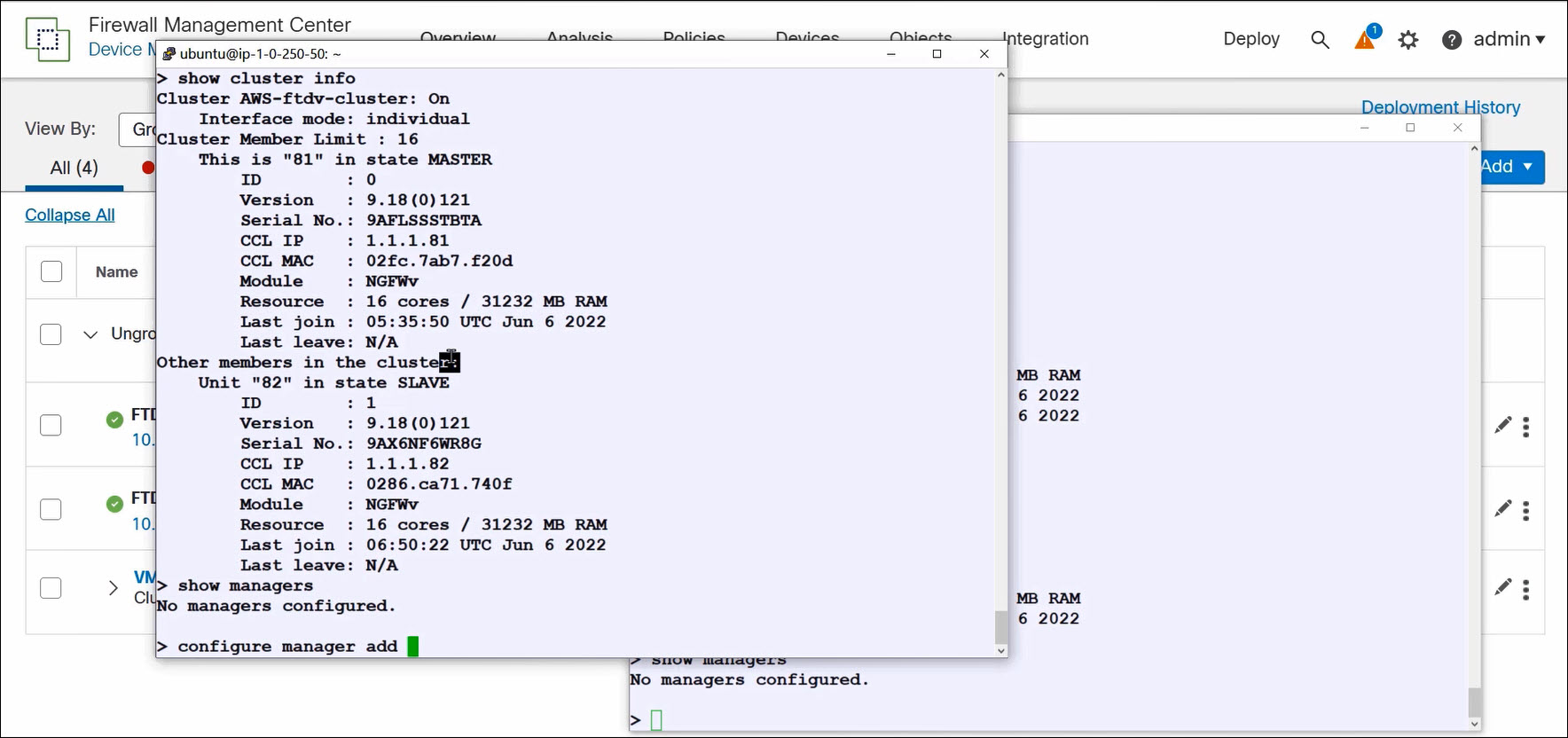
Figure 2. Confirming cluster formation
Navigate to Devices > Device Management and select Add > Device. Register the node configured in the previous step to the FMC as you would register a standalone FTD. Note that you do not select Add > Cluster.
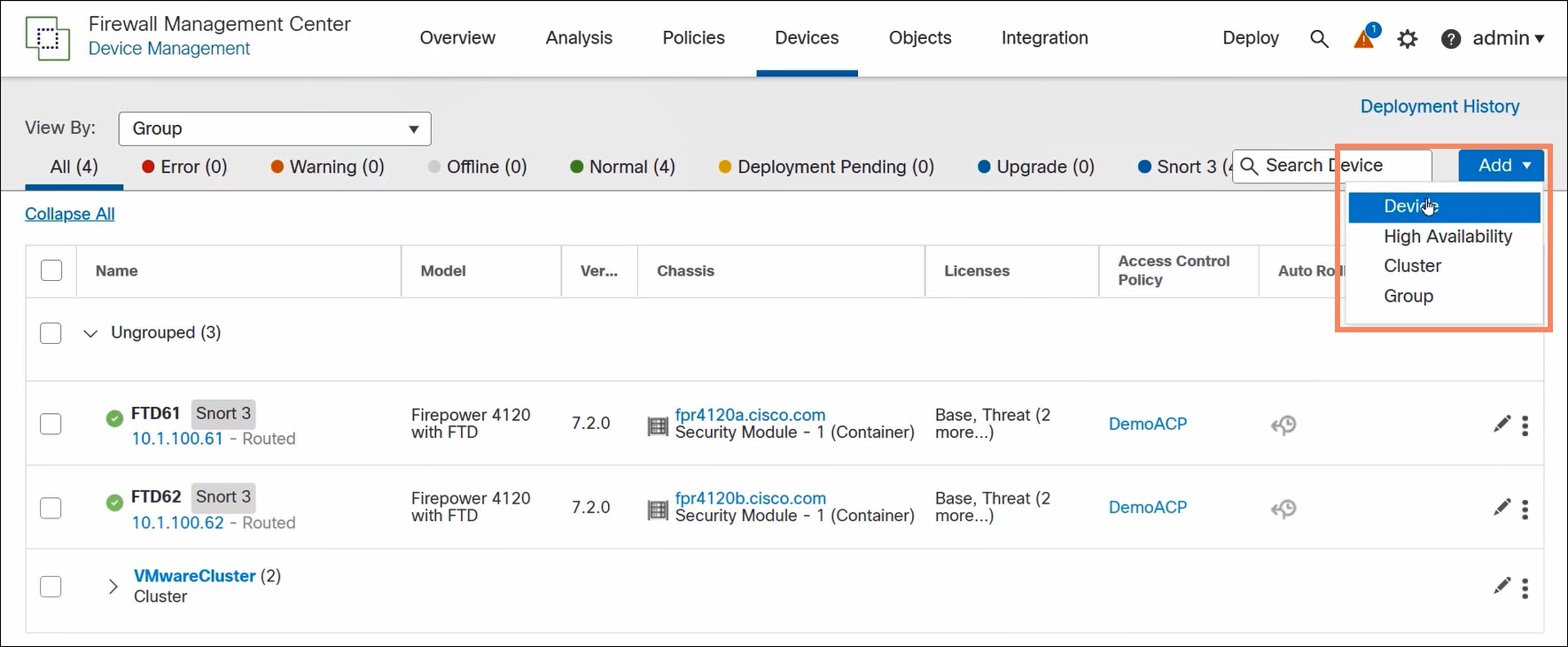
Figure 3. Register a single cluster node
The FMC discovers the cluster configuration and auto-registers the remaining cluster nodes.
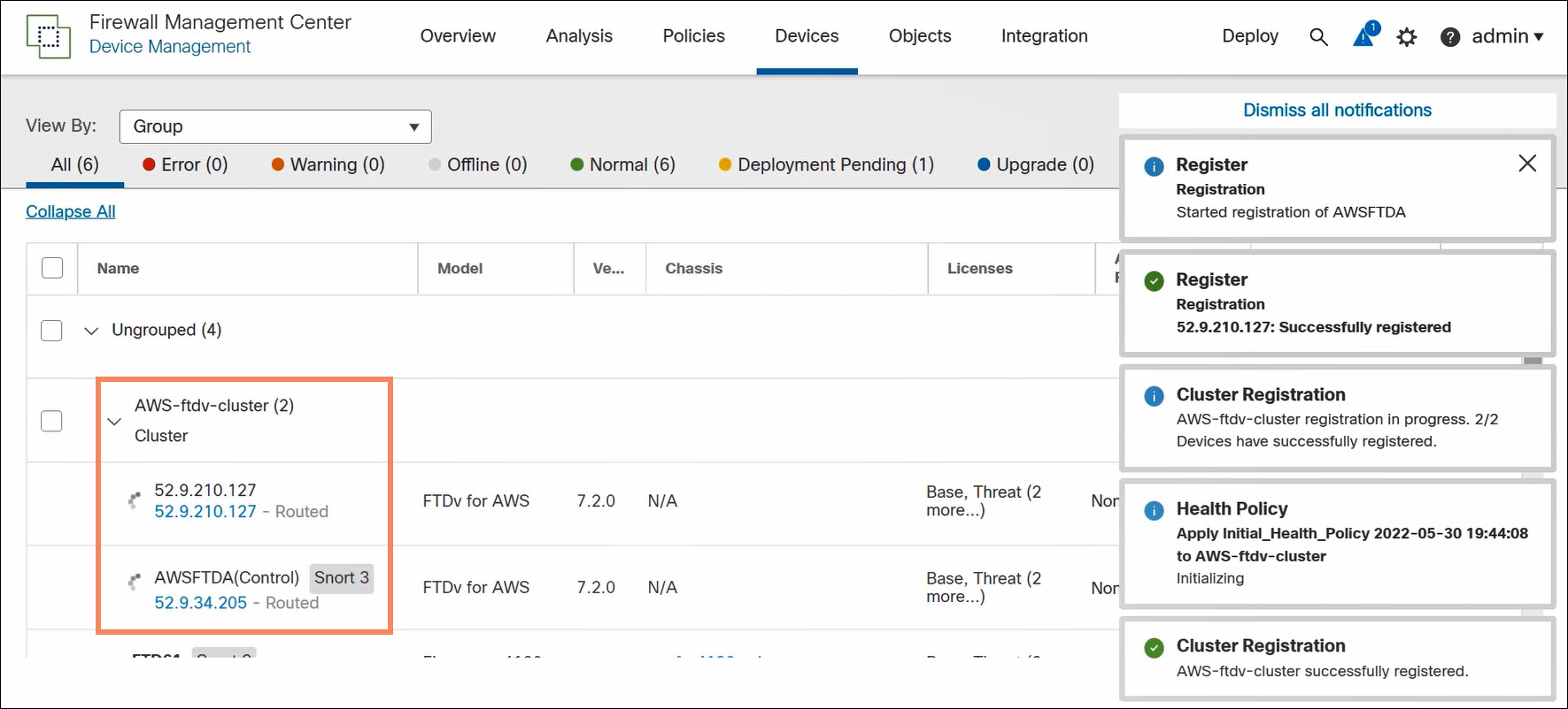
Figure 4. Auto-registration of remaining cluster nodes
Use the FMC to complete the cluster configuration. You can edit the cluster, but you cannot edit the nodes.
Private Cloud (VMware and KVM) Configuration
The FMC builds clusters from private cloud virtual FTDs registered to the FMC.
️ Note
An FTD may have configuration elements incompatible with joining a cluster. Most interface configurations are incompatible. Attempts to form a cluster with this node will fail.
Best practice is to create clusters using freshly registered FTDs.
You can build a cluster out of all desired nodes at once. Or you can create a small (even one node) cluster and then add nodes.
To create a cluster, navigate to Devices > Device Management and select Add > Cluster.
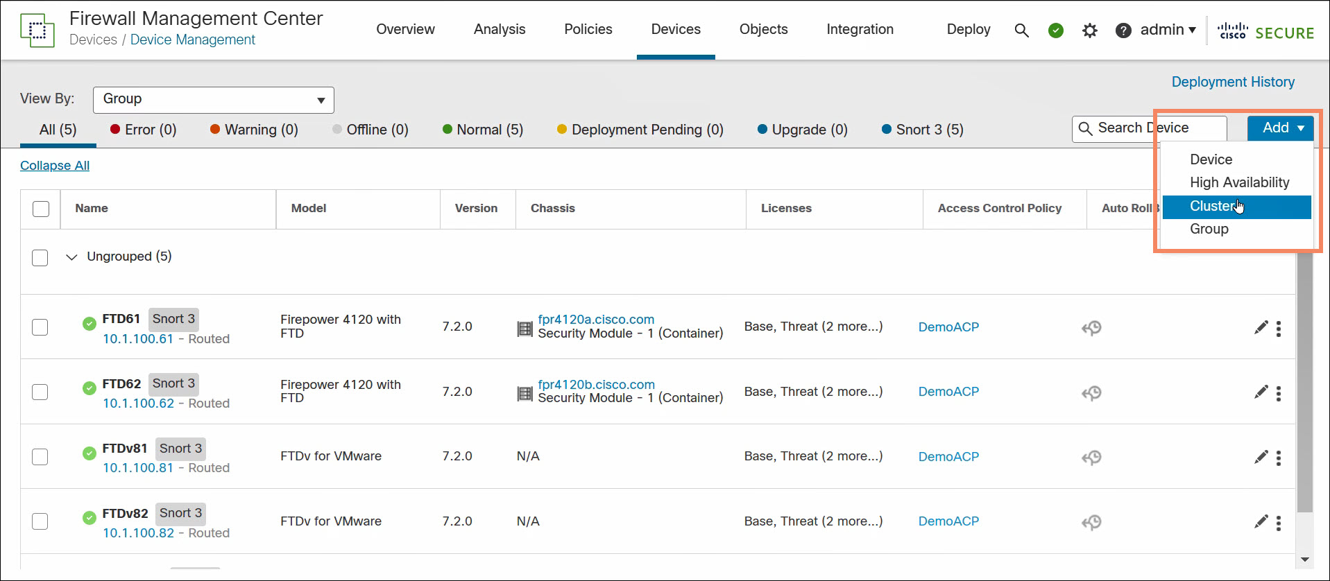
Figure 5. Build a cluster in the FMC
- Name the cluster.
- Optionally enter a cluster key. The cluster key provides encrypted inter-node communication.
- Select the control node. The drop-down list only contains supported FTDs (VMware, KVM, or FPR3000 series devices).
- Define the VXLAN network. The VNIs of the cluster nodes belong to this network.
- Define the VTEP peer group. The FMC auto-assigns VTEP IP addresses from this CIDR. Select the CCL interface.
- Optionally add additional data nodes. The drop-down list only contains supported FTDs.
- Click Continue.
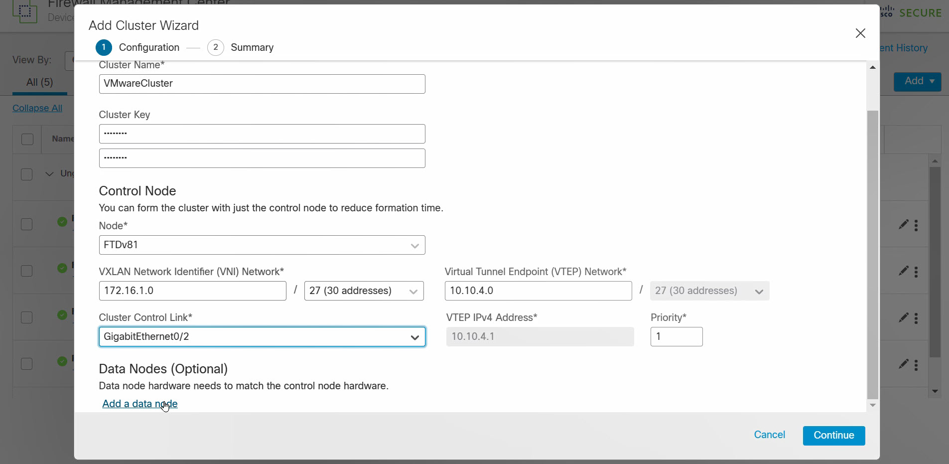
Figure 6. Configure cluster
Review the cluster configuration. Click Save.
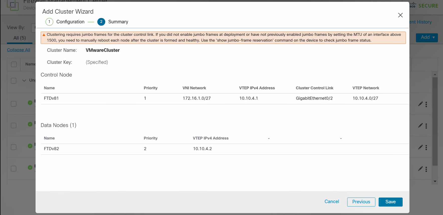
Figure 7. Confirm cluster configuration request
The FMC will build the cluster which takes a few minutes.
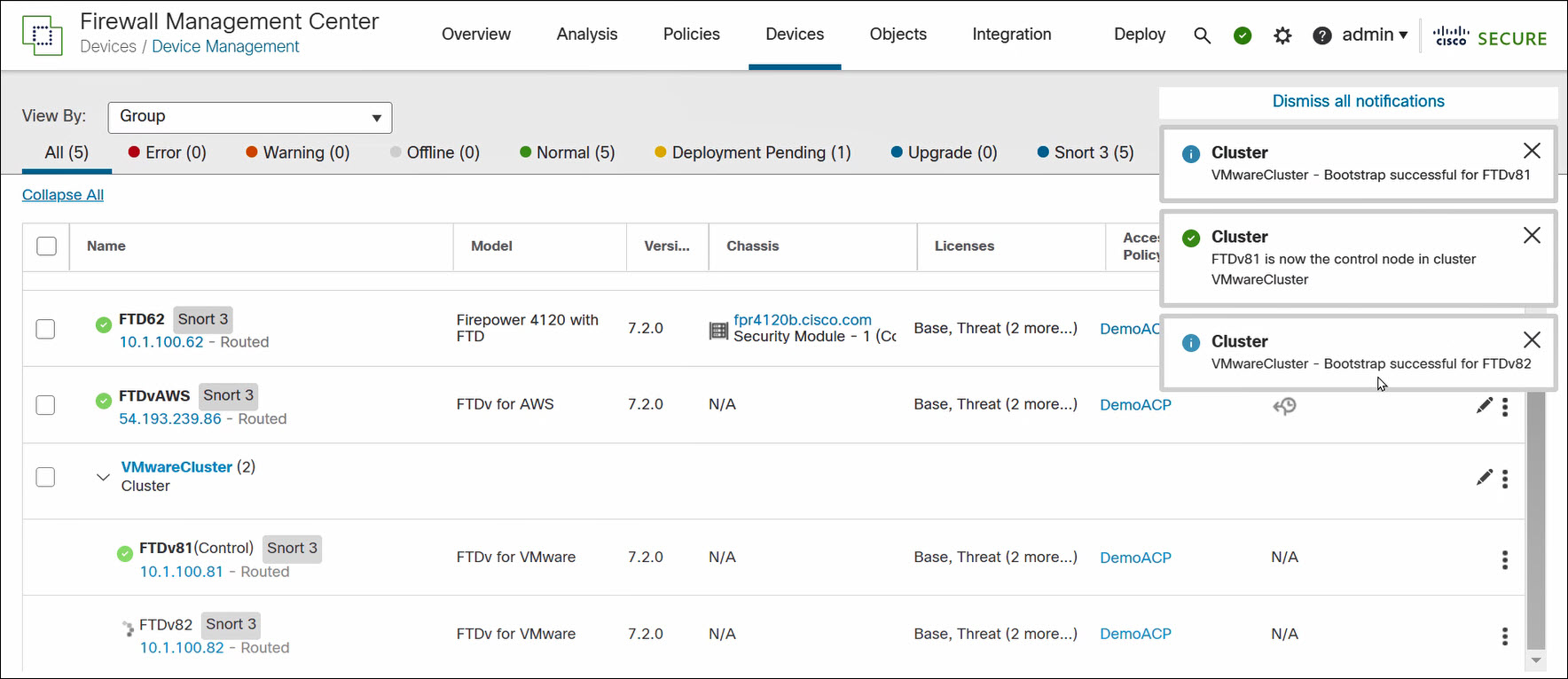
Figure 8. FMC builds cluster
Use the FMC to complete the cluster configuration. You can edit the cluster, but you cannot edit the nodes.
FMC Cluster-Level Operations
Access cluster-level operations in the FMC by clicking on the three vertical dots to the right of the cluster on the Devices > Device Management page.
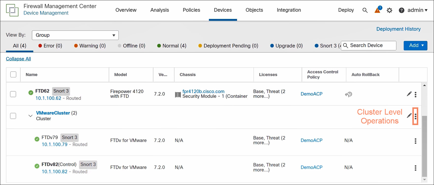
Figure 9. Access cluster-level operations
Cluster-level operations are different for public and private cloud virtual clusters. The FMC can perform more cluster configuration operations on private cloud clusters.
| Public Cloud Cluster-Level Operations | Private Cloud Cluster-Level Operations |
|---|---|
| Cluster Live Status Revert Upgrade Delete Health Monitor Troubleshoot Files | Add Nodes Break Nodes Edit Configuration Cluster Live Status Break Cluster Revert Upgrade Delete Health Monitor Troubleshoot Files |
Cluster Live Status
Use the Cluster Live Status page to monitor the cluster and to perform the following operations:
- Disable node clustering (node-level)
- Change role to control (node-level)
- Reconcile all (cluster-level)
Use Reconcile All if a cluster node does not appear on the device list in the FMC. In the public cloud, this happens if a node is accidentally deregistered. In this case, the Cluster Live Status page shows the node registration pending. Click Reconcile All to register the node with the FMC.
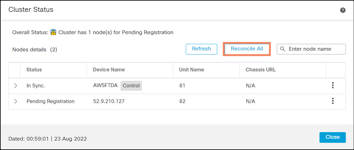
Figure 10. Cluster Live Status page
Node-Level Operations in the FMC
Access node-level operations in the FMC by clicking on the three vertical dots to the right of the nodes on the Devices > Device Management page.
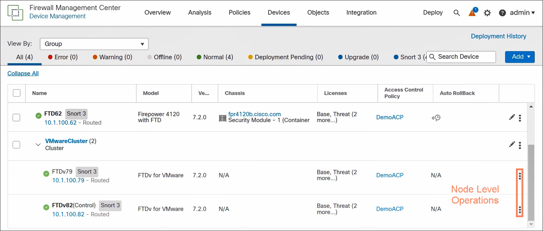
Figure 11. Access node-level operations
Node-level operations are almost identical for public and private virtual clusters, and for control and data nodes. The key differences are the following:
- Delete (public cloud only) deregisters the FTD from the FMC. The FTD remains in the cluster.
- Break From Cluster (private cloud only) removes the FTD from the cluster. The FTD becomes a stand-alone FTD registered to the FMC.
- You cannot select Delete or Break From Cluster for the control node.
| Public Cloud Node-Level Operations | Private Cloud Node-Level Operations |
|---|---|
| Disable Node Clustering Delete Packet Tracer Packet Capture Health Monitor Troubleshoot Files | Disable Node Clustering Break From Cluster Packet Tracer Packet Capture Health Monitor Troubleshoot Files |
Verification and Troubleshooting
Device Configuration for FTD Cluster Behind an AWS GWLB
You should see two NVE and two VNIs. These objects are read-only.
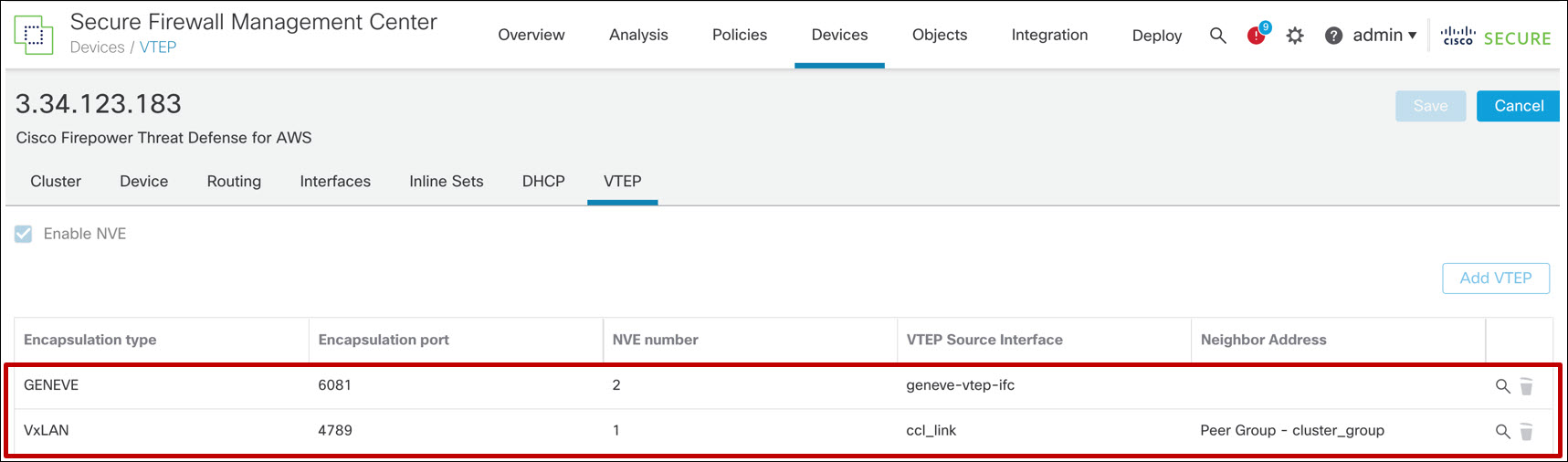
Figure 12. VTEP/NVE configuration for FTD cluster behind an AWS GWLB
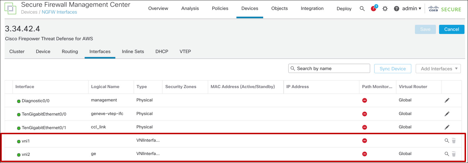
Figure 13. VNI configuration for FTD cluster behind an AWS GWLB
Device Configuration for All Other Cases
You should see one (VXLAN) NVE and one VNI. These objects are read-only.
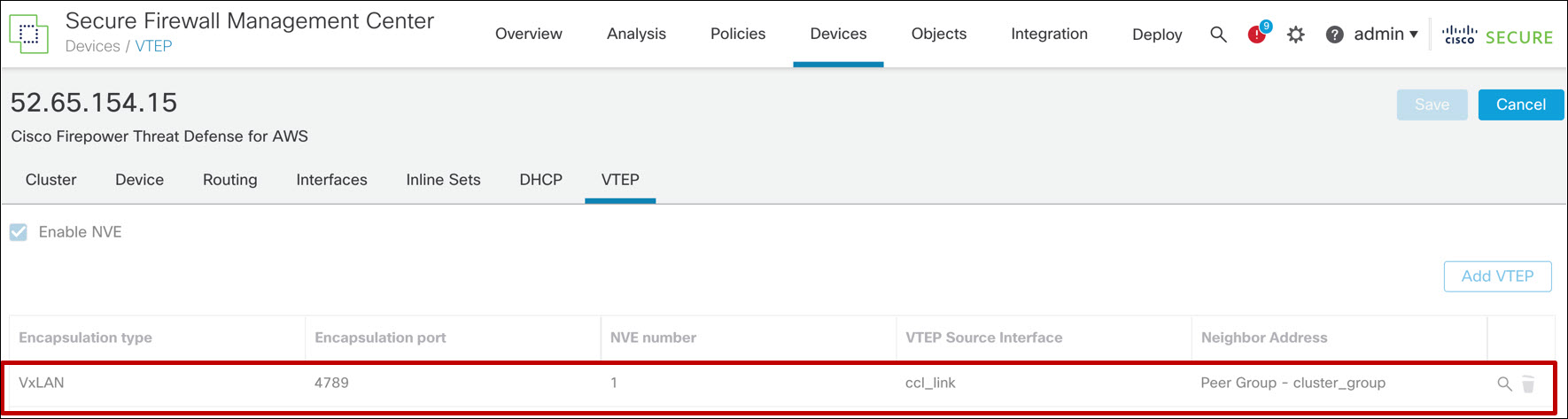
Figure 14. VTEP/NVE configuration for FTD cluster deployed without an AWS GWLB
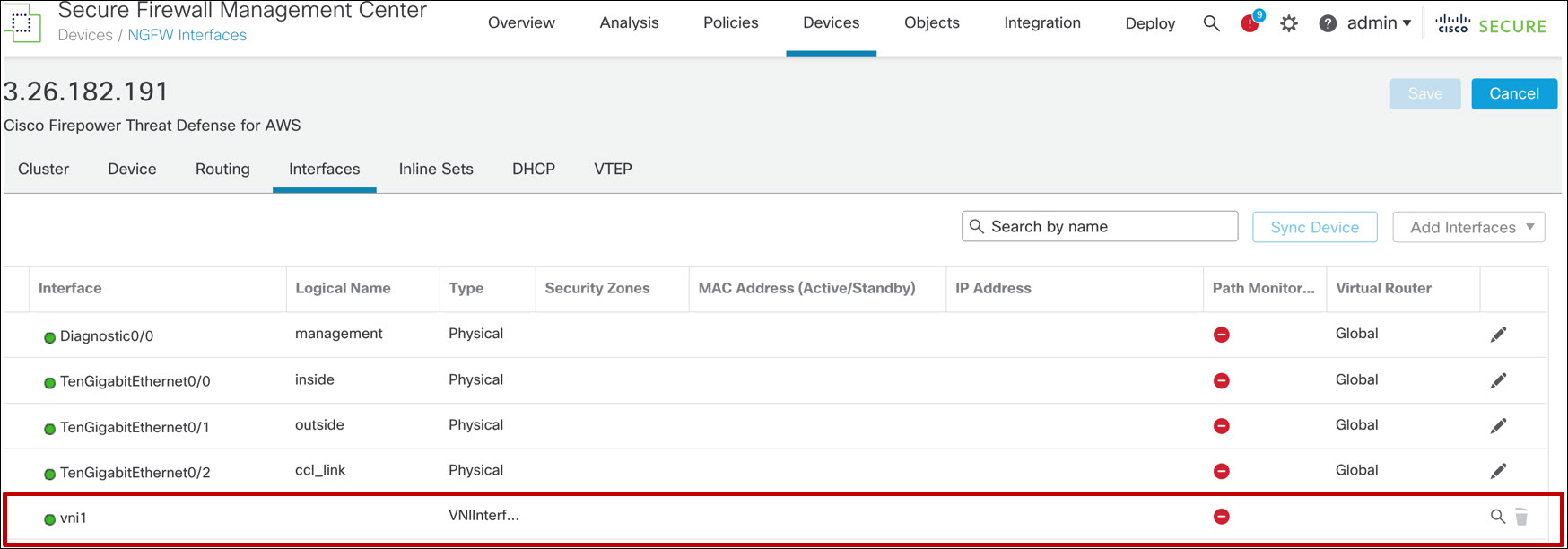
Figure 15. VNI configuration for FTD cluster deployed without an AWS GWLB
FTD CLI Commands
Use the show cluster info command to confirm that the cluster has formed. There are subcommands that provide more detailed information. Type show cluster info ? to see how to use these subcommands. Note that on AWS and GCP you can run this command before you register the FTDs to the FMC.
> show cluster info
Cluster AWS-ftdv-cluster: On
    Interface mode: individual
Cluster Member Limit : 16
    This is "81" in state MASTER
        ID        : 0
        Version   : 9.18(0)121
        Serial No.: 9AFLSSSTBTA
        CCL IP    : 1.1.1.81
        CCL MAC   : 02fc.7ab7.f20d
        Module    : NGFWv
        Resource  : 16 cores / 31232 MB RAM
        Last join : 05:35:50 UTC Jun 6 2022
        Last leave: N/A
Other members in the cluster:
    Unit "82" in state SLAVE
        ID        : 1
        Version   : 9.18(0)121
        Serial No.: 9AX6NF6WR8G
        CCL IP    : 1.1.1.82
        CCL MAC   : 0286.ca71.740f
        Module    : NGFWv
        Resource  : 16 cores / 31232 MB RAM
        Last join : 06:51:30 UTC Aug 6 2022
        Last leave: 06:48:59 UTC Aug 6 2022
>
Note
In public cloud clusters, if the output of this command says Clustering is not configured, it is possible the day-0 configuration is incorrect. You can examine and modify this information. Details and caveats are different for each of the public cloud environments.
If the output of the show cluster info command shows nodes forming single node clusters, check the communication between the nodes across the cluster link.
The show nve provides detailed information about VTEP peers, and NVE and VTEP configuration. You must use the diagnostic CLI on the FTD to execute this command.
> system support diagnostic-cli
FTD81> enable
Password:
FTD81# show nve
Attaching to Diagnostic CLI ... Press 'Ctrl+a then d' to detach.
Type help or '?' for a list of available commands.

nve 1, source-interface "ccl_link" is up (nve-only cluster is ON)
 IP address 10.100.255.81, subnet mask 255.255.255.0
 Encapsulation: vxlan
 Encapsulated traffic statistics:
   8397379 packets input, 1554561962 bytes
   8513596 packets output, 2371077126 bytes
   252 packets dropped
 Number of configured static peer VTEPs: 0
Configured static peer group VTEPs:
	IP address 10.100.255.253
```
	IP address 10.100.255.82 MAC address 0286.ca71.740f (learned)
```
	IP address 10.100.255.2
 Number of discovered peer VTEPs: 1
    Discovered peer VTEPs:
        IP address 10.100.255.82
 Number of VNIs attached to nve 1: 1
 VNIs attached:
        vni 1: proxy off, segment-id 1, mcast-group none
 NVE proxy single-arm channel is off.
FTD81#
Look for the learned MAC address as evidence that the VXLAN is working. Number of configured static peer VTEPs will always be 0 This is because the cluster bootstrap creates a VXLAN peer group instead of a static peer.
You can use ping between the VTEP interfaces from the FTD CLI to confirm connectivity provided you network allows ICMP traffic.
📚Additional Resources
The following references provide additional information.
- This document is a recommended prerequisite: VXLAN and GENEVE Support.
- These sections of the Cisco Secure Firewall Management Center Device Configuration Guide, 7.2 covers cluster configuration for FTD:
- Cisco provides get started guides for each cloud platform: Cisco Secure Firewall Threat Defense Virtual Getting Started Guide
- Andrew Ossipov provides an excellent deep-dive on clustering focused on physical devices: BRKSEC-3032 - Cisco Live
- This YouTube video demonstrates clustering of both public and private virtual firewalls: Clustering Virtual Firewalls
- For integration of the Cisco Secure Firewall with the Azure GWLB, see the following: Azure Gateway Load Balancer
- For integration of the Cisco Secure Firewall with the AWS GWLB, see the following:
Updated over 3 years ago