Device Registration and Initial Setup
Cisco Internal Use Only for Secure Firewall Roadshow Ignite Event
Overview
This lab utilizes NGFW1 and NGFW2, which are virtual Firewalls in your dCloud session. These are registered to the Firewall Management Center (FMC), where we will manage the device, policy enforcement, etc. We will also set up the Firewalls with initial configuration for the upcoming lab scenarios.
Scenario 0: Familiarization with dCloud Environment
Environment Overview
-
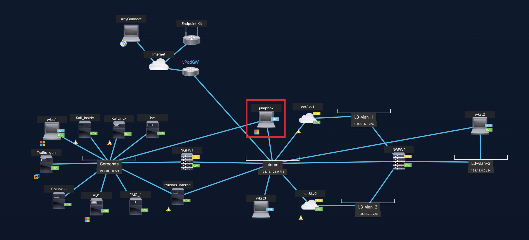
Because you are viewing this lab guide we assume you have started your dCloud session and are ready to begin. Click the View button by your session to see the lab topology.

Figure 2: dCloud Session
Note
If your dCloud session was recently shared, it may take a few minutes for the View button to appear while the lab virtual machines boot up.
- You will see the lab topology.
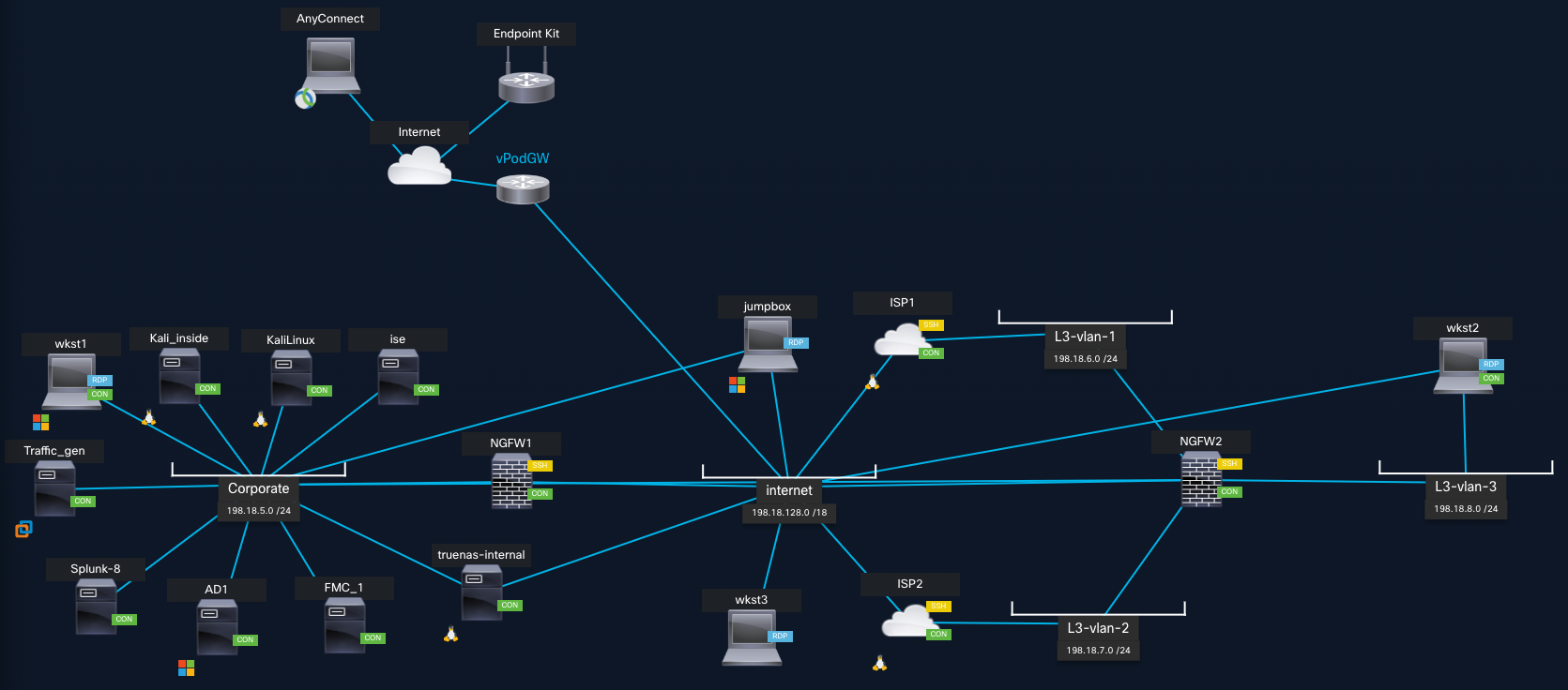
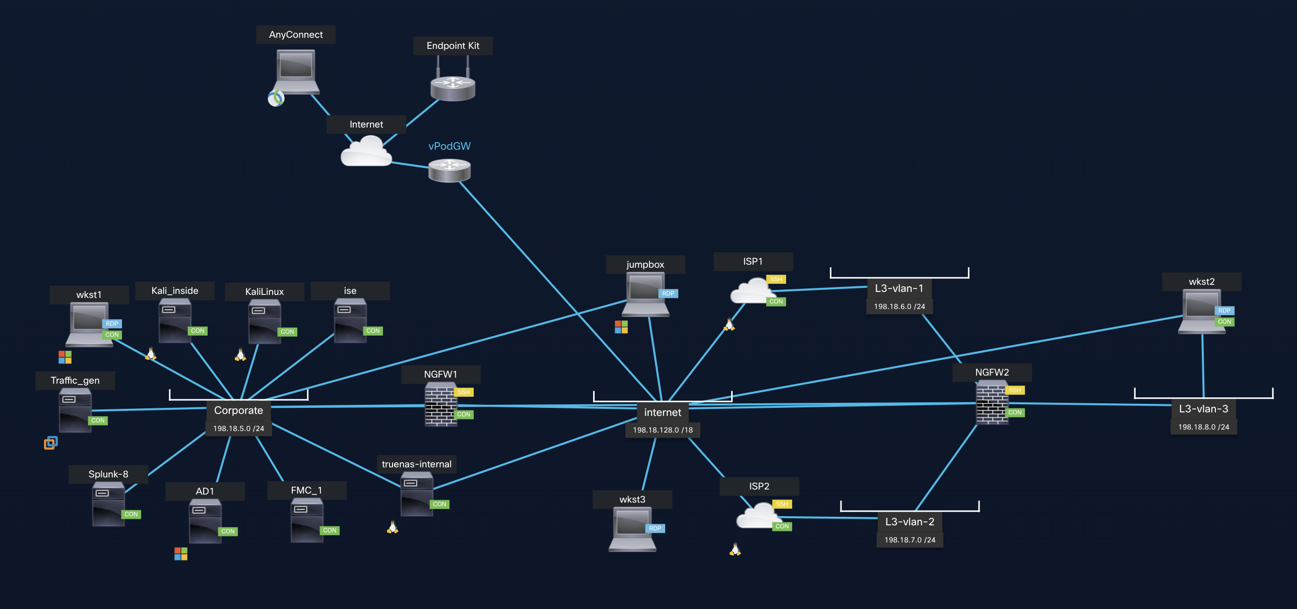
Figure3: dCloud Topology
- The dCloud active topology page provides an overview of your dCloud pod. For reference purposes, as you are performing the labs, you can refer to the topology for credentials, IP addresses, interfaces, subnets, RDP addresses, etc.
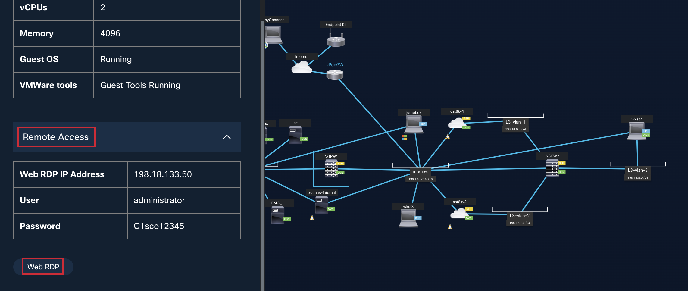
- On the topology window, locate the Jumpbox. Click on its icon (on the computer screen). A popup for the Jumpbox should open. The Jumpbox is a Windows machine: it will act as our Admin-PC for the session. This machine has multiple Network Interface Cards (NICs) on different subnets. Sometimes the Jumpbox will act as the Admin PC at the Corporate Head Office, and at other times, it will act as the Admin PC for the Branch office, etc. The credentials for the Jumpbox and all other Windows machines are administrator / C1sco12345.
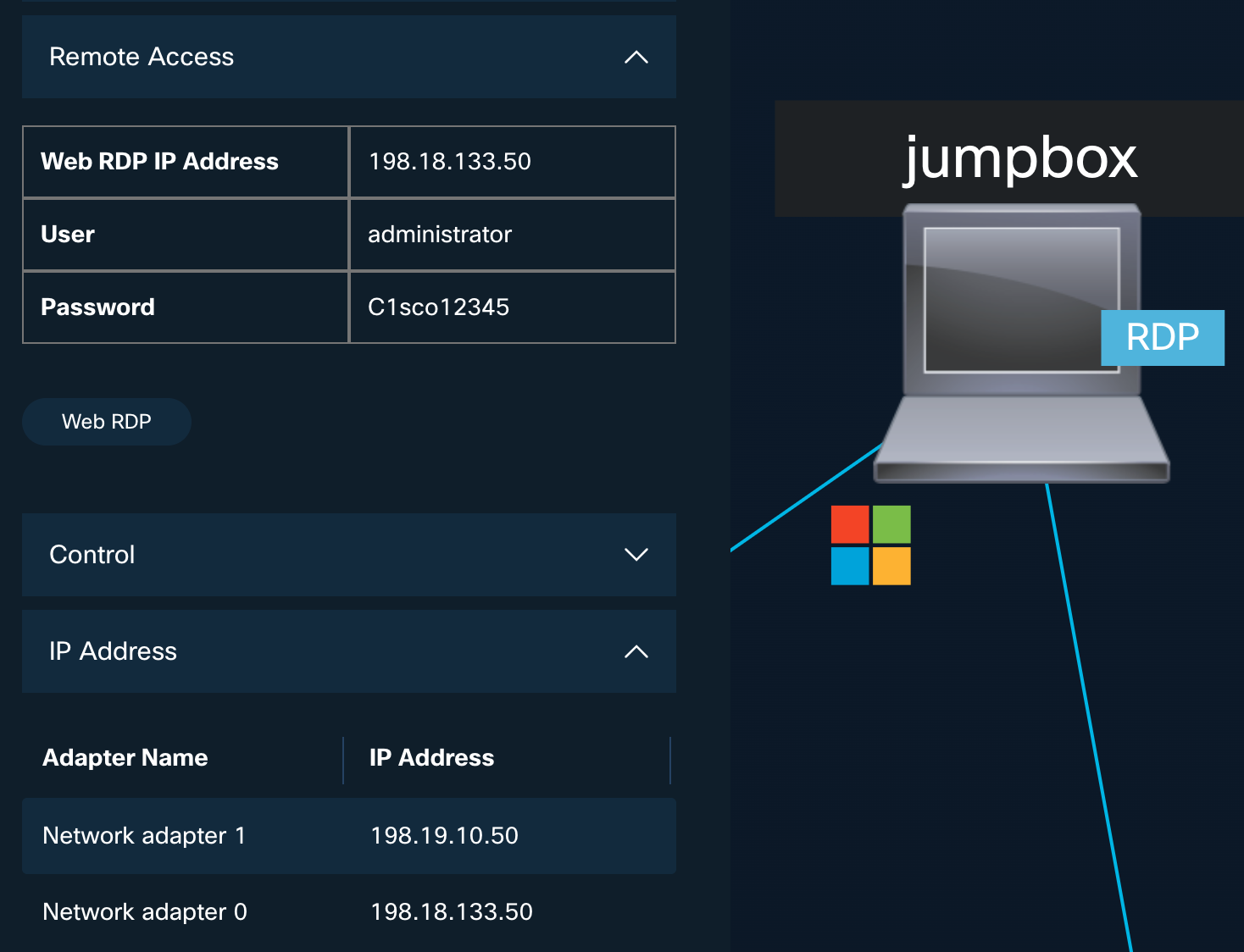
Figure 4: Jumpbox Access
- From the Jumpbox popup, click Web RDP to connect to it.
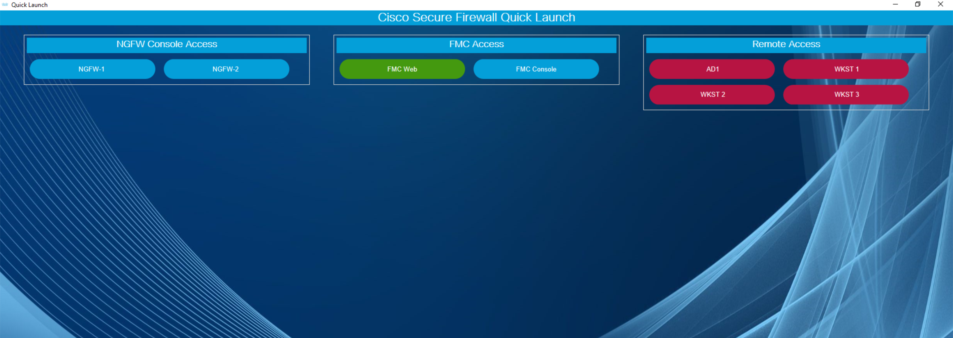
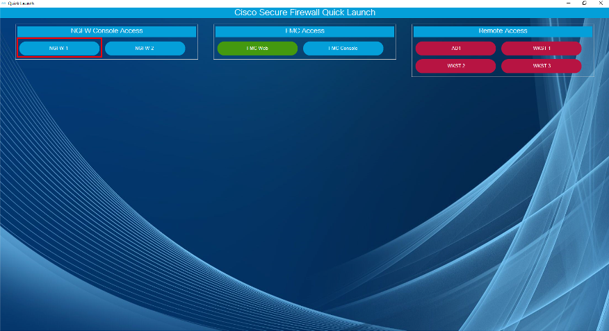
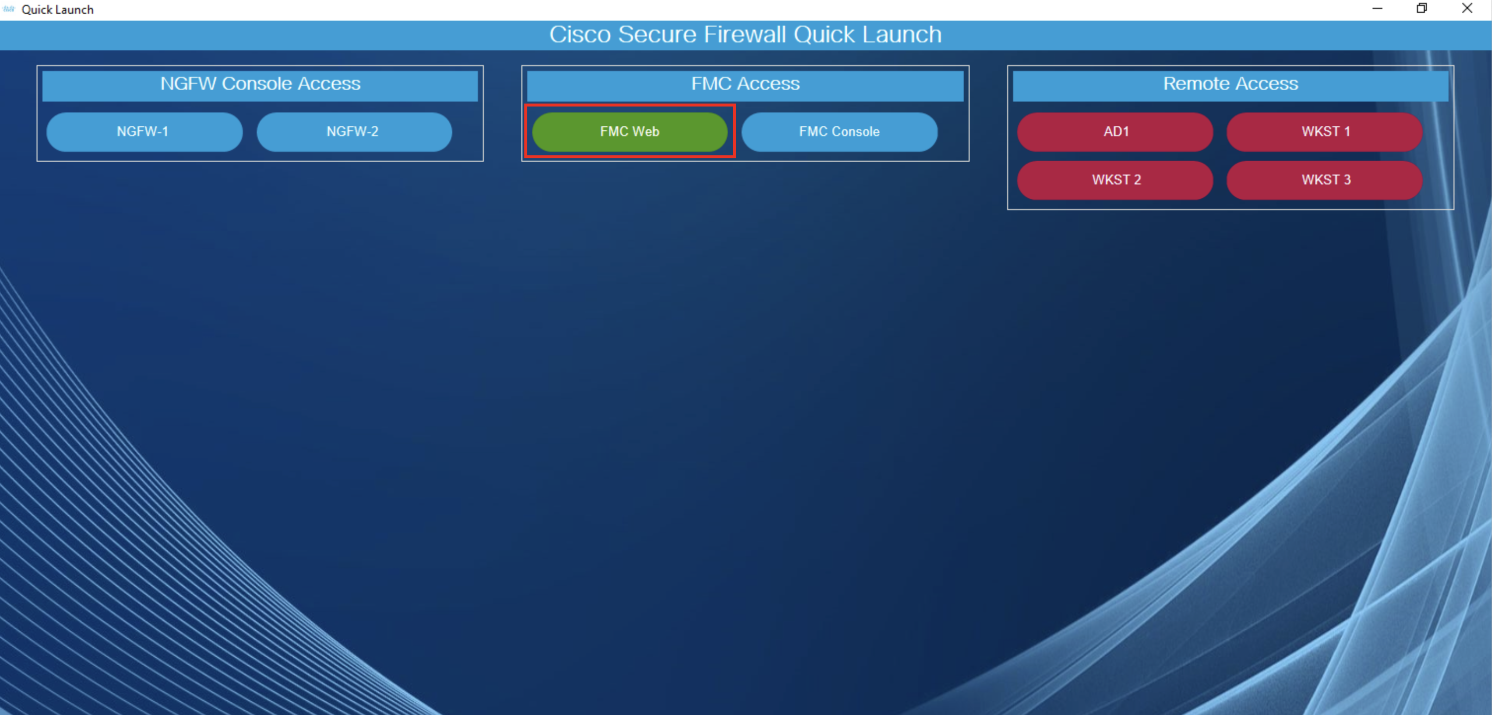
- The first time you connect to the Jumpbox, Windows will automatically launch Quick Launch. This is a web page providing you shortcut access to devices used in our lab scenarios. Have a look at some of the names on the menu. You will recognize devices also seen on the topology found at the beginning of this document.
-
Blue buttons open Putty SSH sessions.
-
Green buttons open browser sessions.
-
Red buttons open RDP sessions.
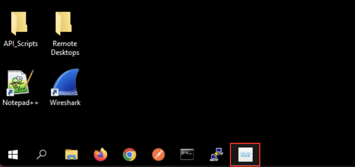
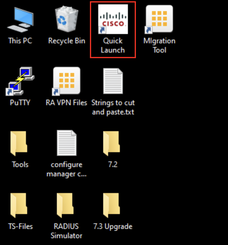
- If you close the Quick Launch and want to open it again use the icon on the desktop.
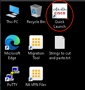
Closing Quick Launch Application
Display Improvements
- To get crisper fonts on Jumpbox, perform a Windows search for ClearType.

ClearType Search
- Turn on ClearType. The improvement will be immediate.
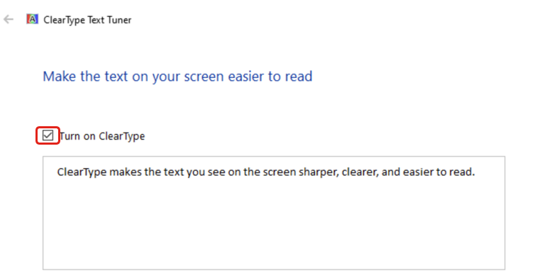
ClearType Activation
Time Synchronization (Important)
- Next, the time on the Jumpbox must be properly synchronized. Verify that the workstation time in the lower right corner is correct. It should show the correct time on your desktop's timezone. If this time is correct, you can continue with the lab exercises.
- If this time is not correct, resynchronize the clock using the following procedure:
- Right-click on the time in the lower right and select Adjust date/time from the menu.
- Click the Sync now button in the dialog
- Confirm the Jumpbox time is now set correctly.
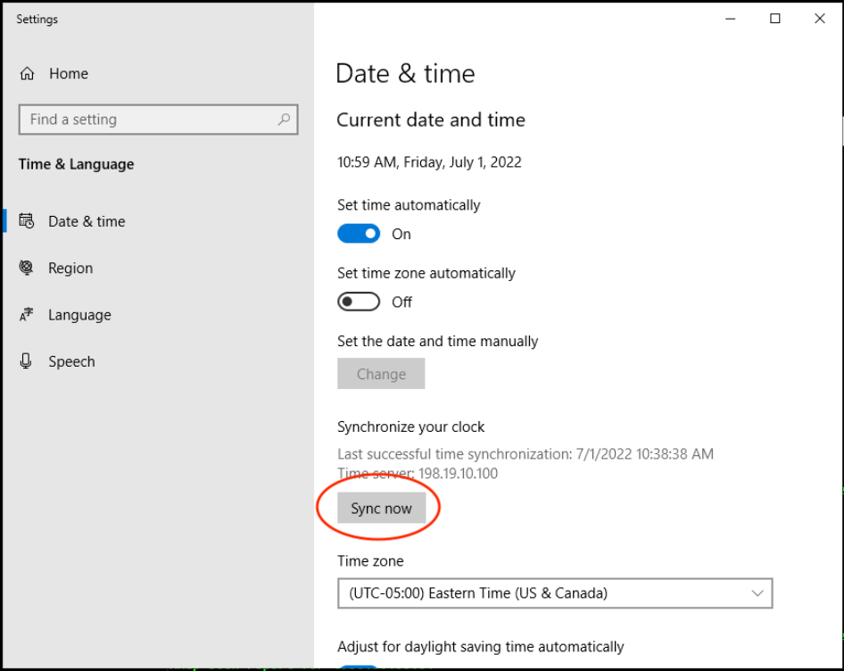
Date & Time Synchronization
Success
Your dCloud session is available, and synchronized.
Topology
Lab Tasks Overview
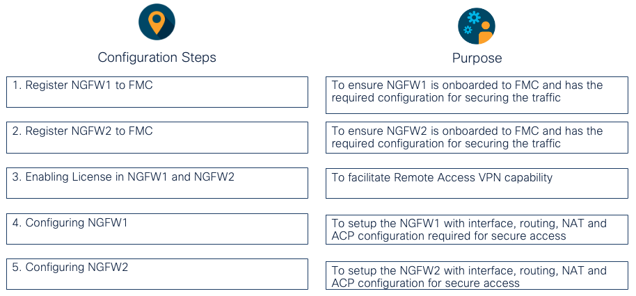
Task 1 - Register NGFW1 to FMC
Warning
Google Chrome is suggested to be used for performing this lab.
-
Click on the Jumpbox machine in the dCloud topology and under Remote Access click on Web RDP.
-
A new tab appears named "jumpbox," which takes you to the Quick Launch window. Now click NGFW-1 under the NGFW Console Access section.
NOTE:
If it doesn't immediatly appear, start in the dCloud jumpbox tab, go to the bottom ribbon and clickQuick Launch or alternatively Quick Launch from the desktop shortcut. Then click on NGFW-1 under the NGFW Console Access section shown below:
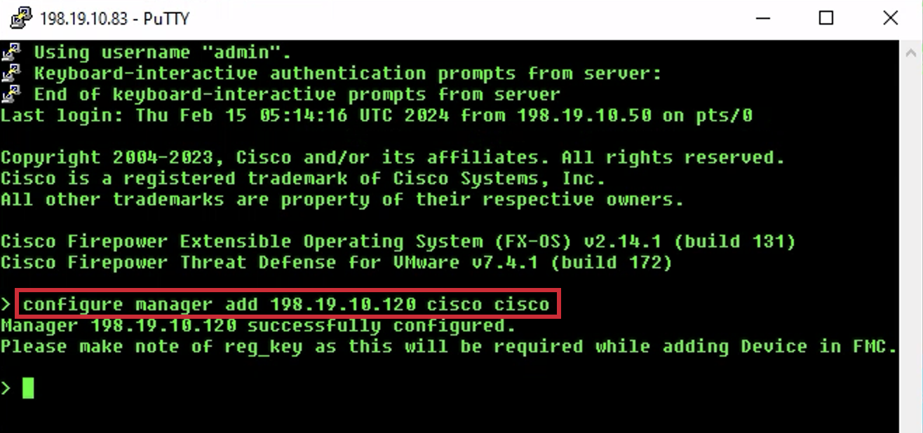
- At the CLI prompt type configure manager add 198.19.10.120 cisco cisco and press Enter. This command sets the on-prem FMC as the manager for NGFW1.
- Go back to Quick Launch and click FMC Web to open the FMC web interface.
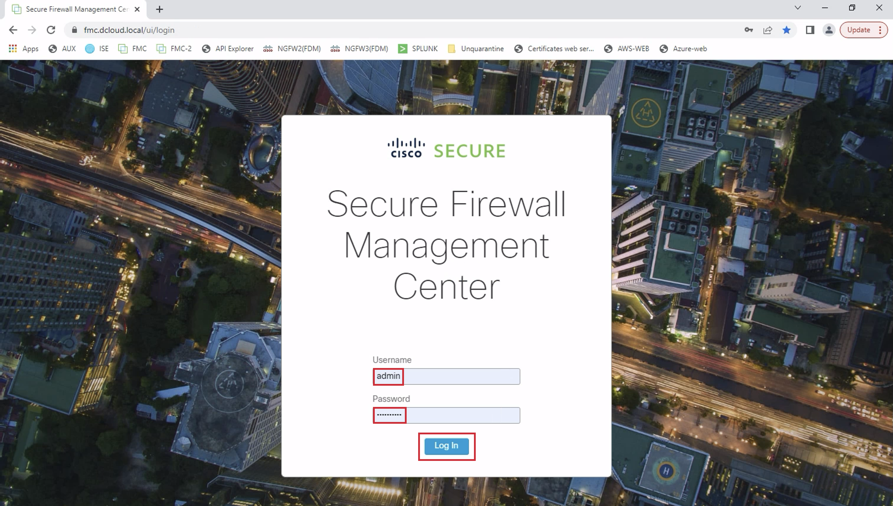
- Login with credentials admin/dCloud123! and click on Log In.
Note
Click on Accept if there is an End User License Agreement displayed.
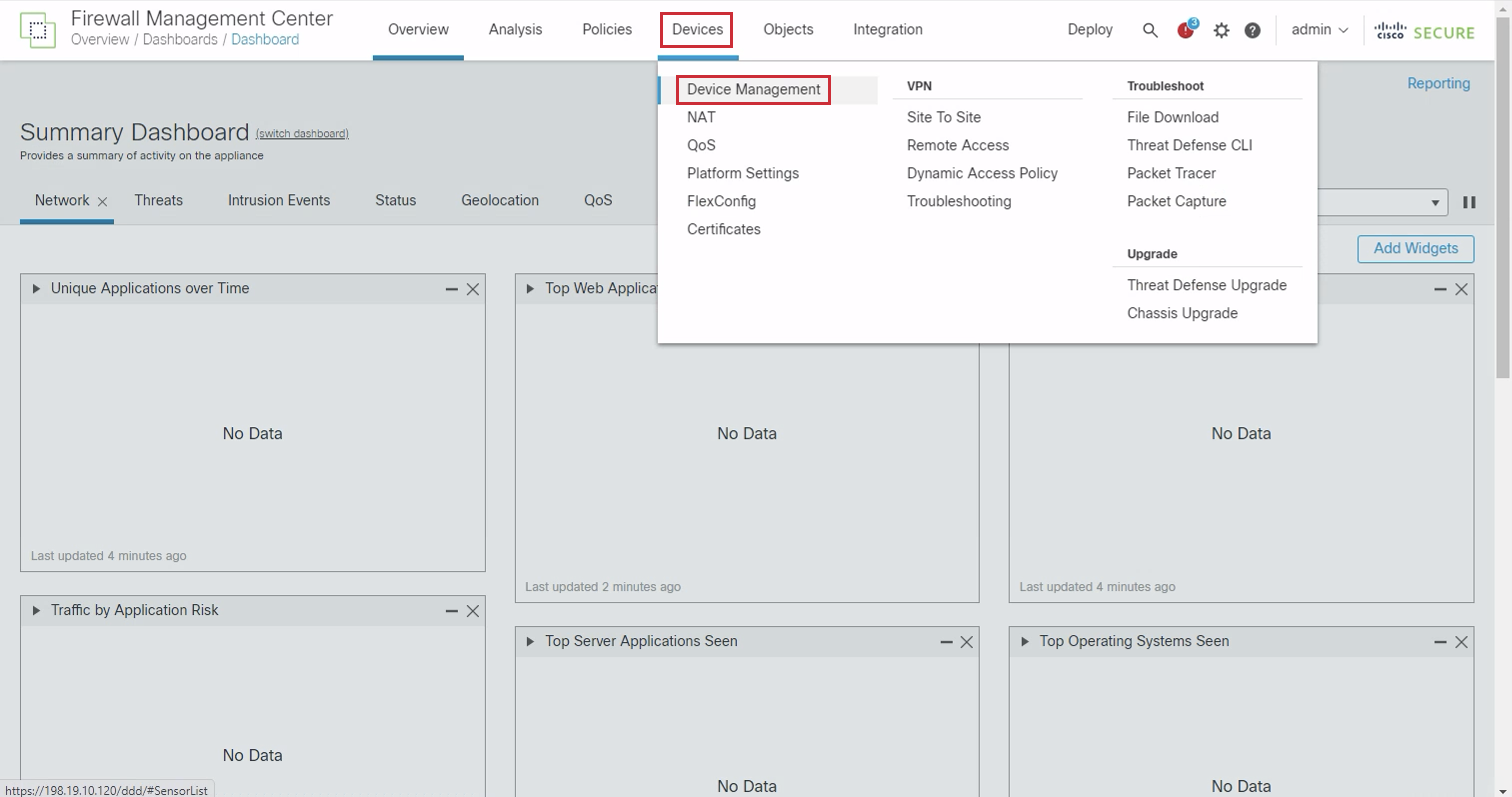
- Navigate to Devices > Device Management.
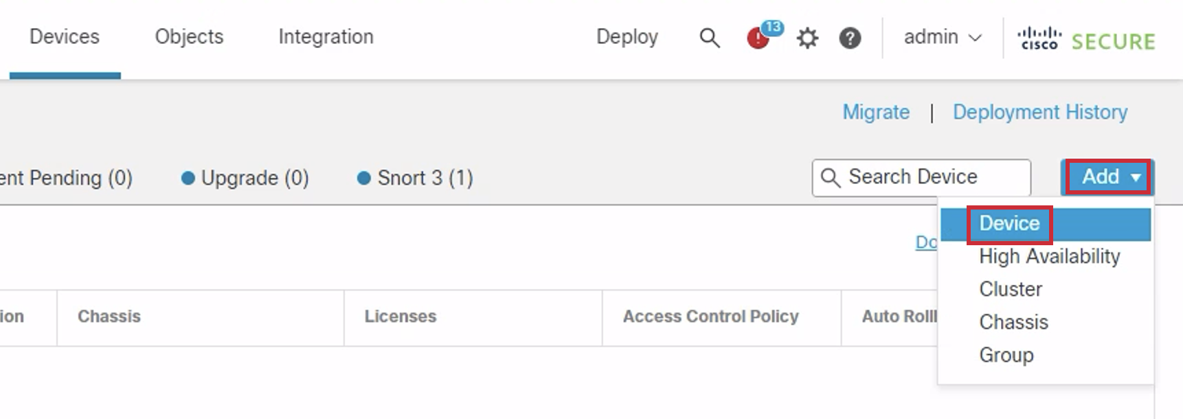
- Click the Add dropdown on the right side and select Device.
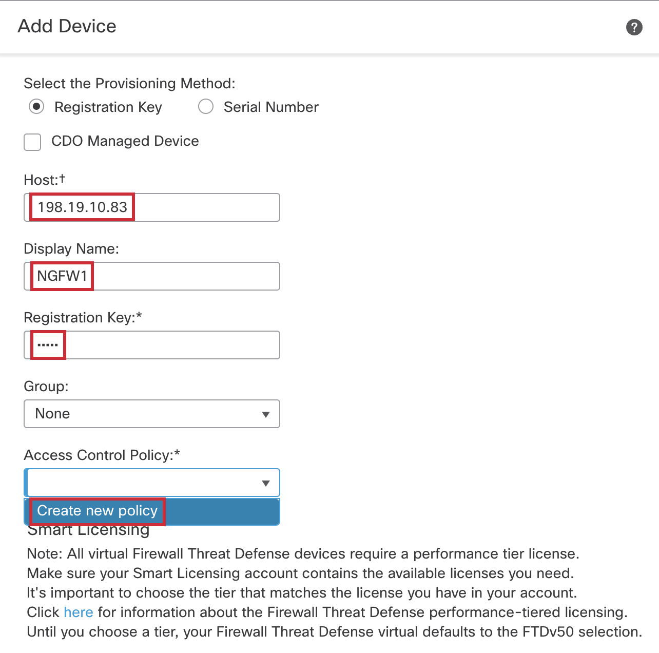
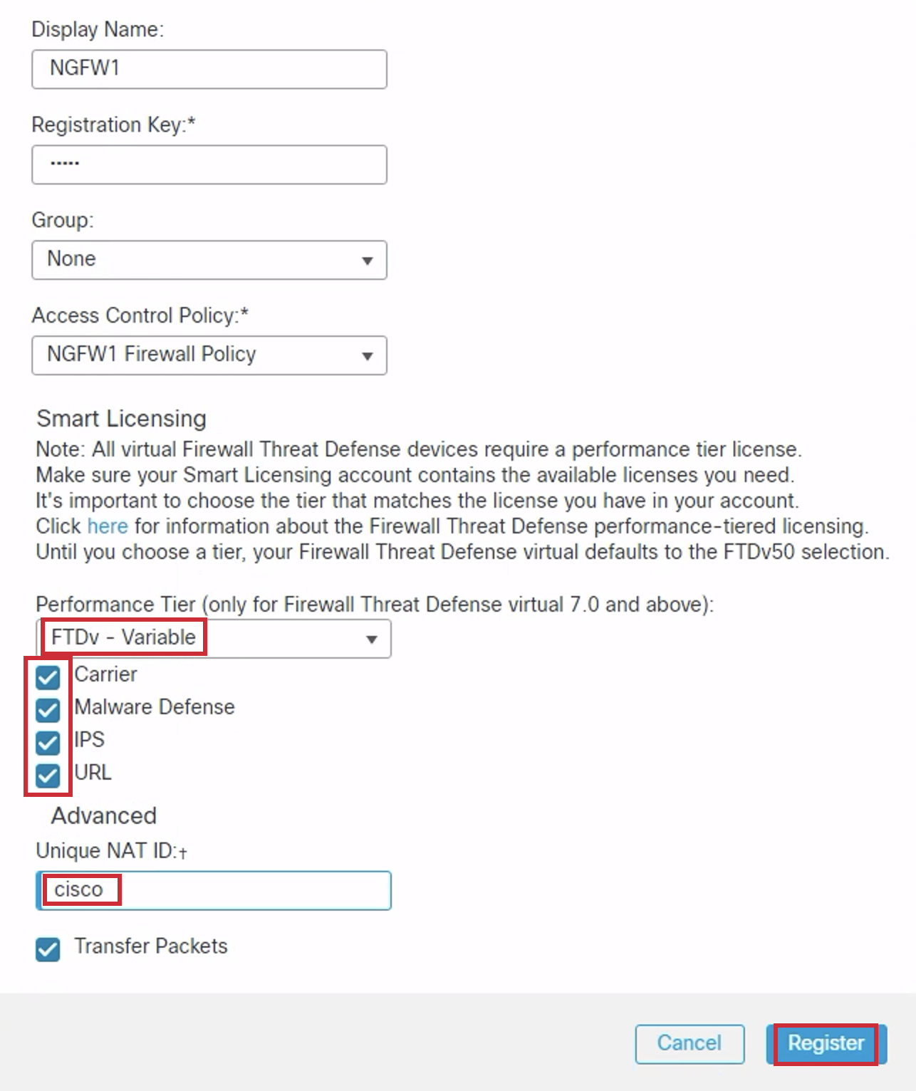
- Enter the following into the Add Device dialog:
- Host: 198.19.10.83
- Display Name: NGFW1
- Registration Key: cisco
- Group: None
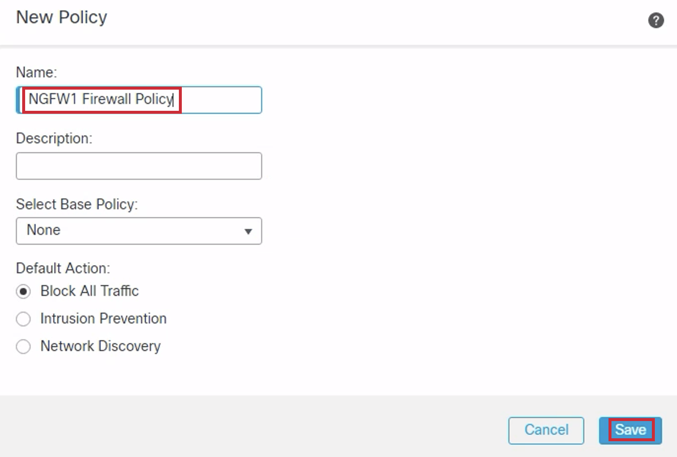
- Access Control Policy: Click on Create New Policy from the drop-down and enter the following into the New Policy dialog:
- Name: NGFW1 Firewall Policy
- Leave the rest of the fields as they are (default).
- Click Save.
- You're returned to the Add Device window with the Access Control Policy saved.
- Find Performance Tier and select: FTDv - Variable
- Check the Carrier, Malware Defense, IPS, and URL boxes
- Unique NAT ID: cisco
- Click Register to start the registration process.
NOTE:
The limits for the different performance tiers are as below:
FTDv Variable is chosen to maintain the current license compliance.
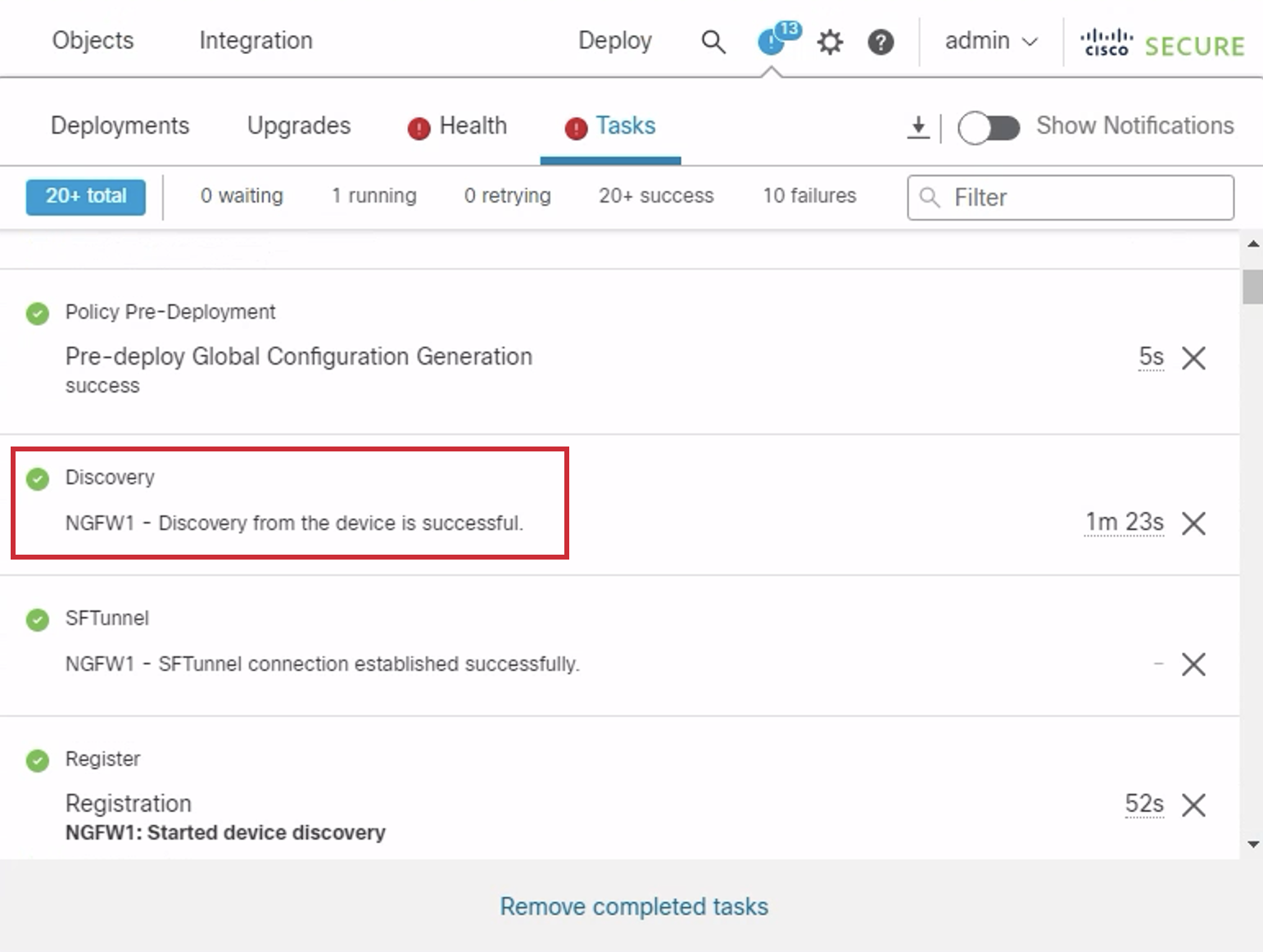
- Registration takes ~8-10 minutes to complete. To track progress, go to Notifications in the top right ribbon and click the Tasks tab. The image below shows you what a successful registration looks like.
Note
Discovery and Policy deployment will continue in the background. You can proceed with the next step.
Task 2 - Register NGFW2 to FMC
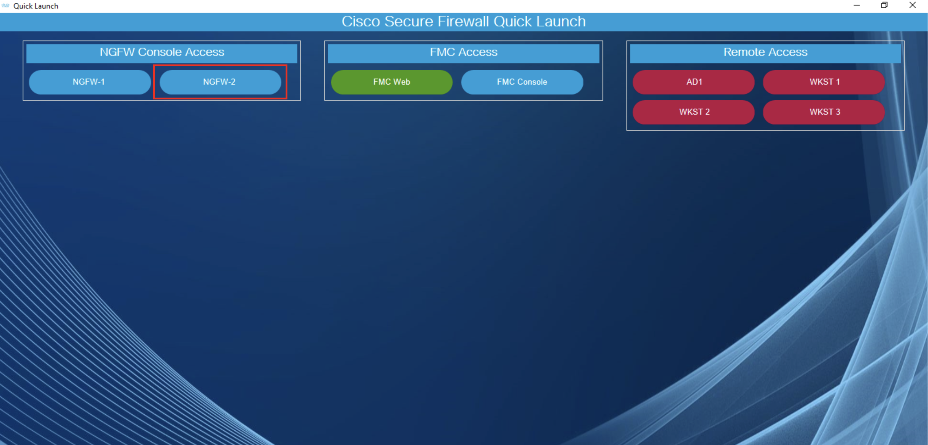
- Back in the dCloud jumpbox, open Quick Launch . Click on NGFW-2 under the NGFW Console Access section shown below:
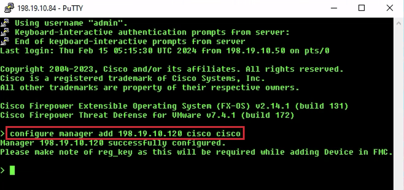
- At the CLI prompt type configure manager add 198.19.10.120 cisco cisco and press Enter. This command sets the on-prem FMC as the manager.
- Navigate back to the Firewall Management Center on Google Chrome.
- Click the Add dropdown on the right side and select Device.
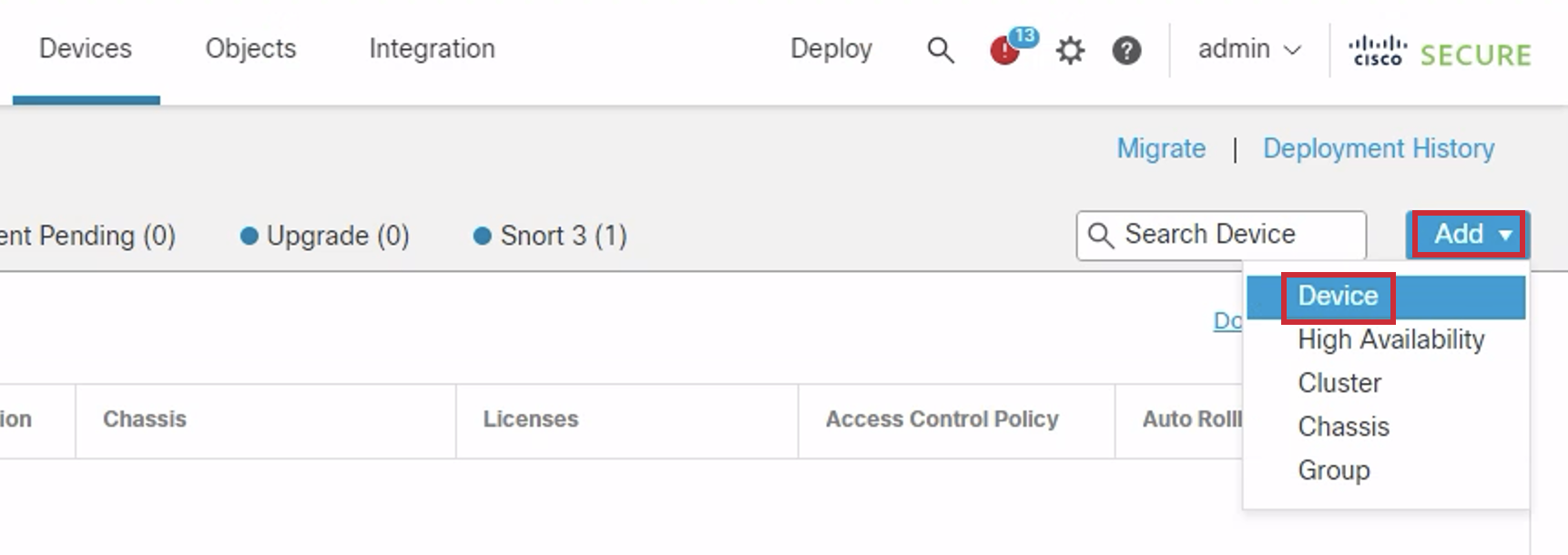
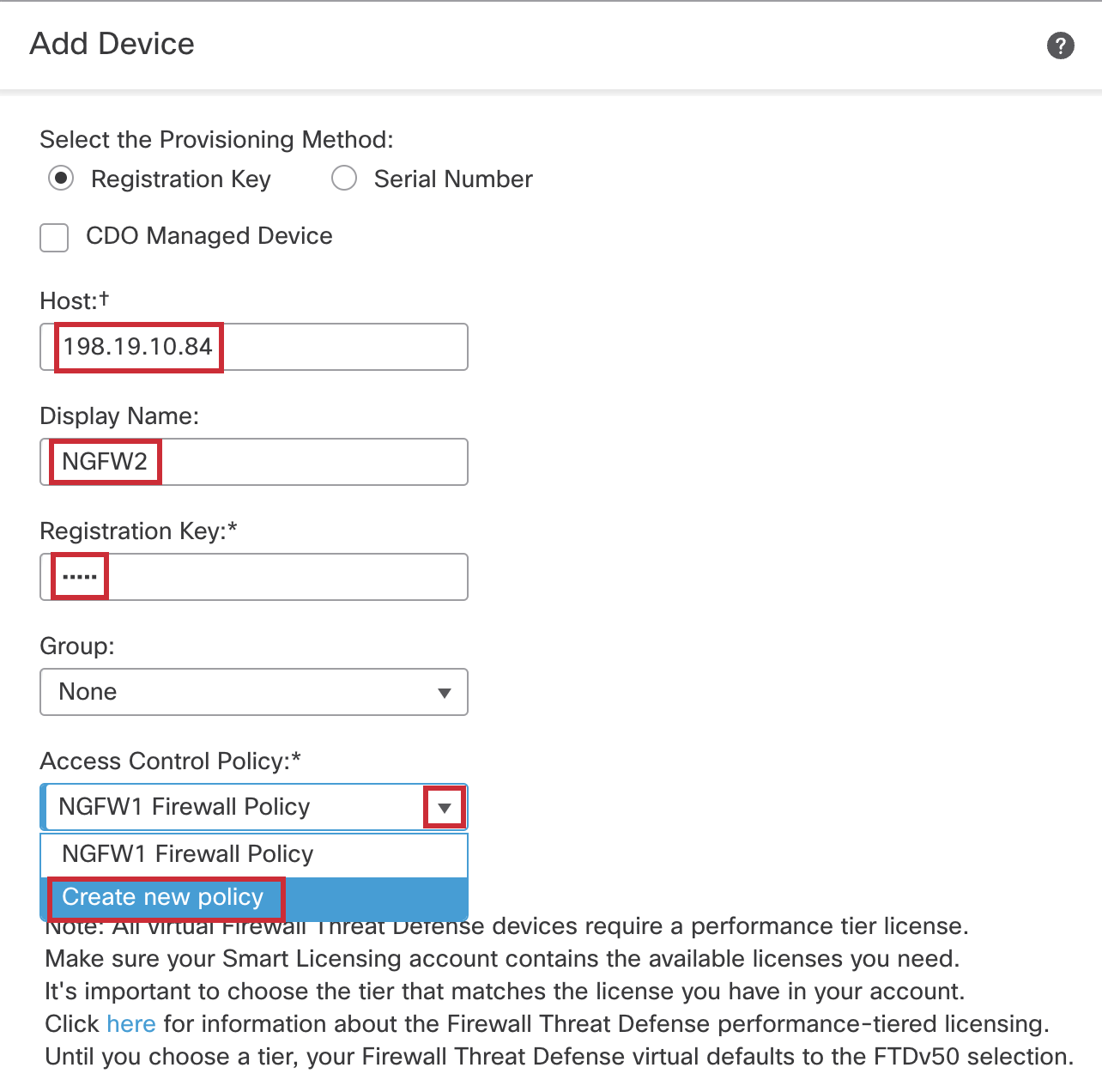
- Enter the following into the Add Device dialog:
- Host: 198.19.10.84
- Display Name: NGFW2
- Registration Key: cisco
- Group: None
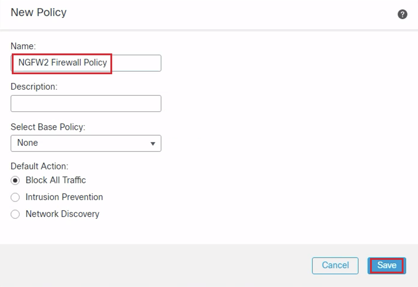
- Access Control Policy: Click Create New Policy from the drop down and enter the following into the New Policy dialog:
- Name: NGFW2 Firewall Policy
- Leave the rest of the fields as they are (default).
- Click on Save.
-
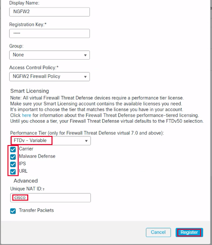
You're returned to the Add Device window with the Access Control Policy saved.
- Find Performance Tier and select: FTDv - Variable
- Check the Carrier, Malware Defense, IPS, and URL boxes
- Unique NAT ID: cisco
- Click on Register to start the registration process.
-
Registration takes ~8-10 minutes to complete. To track progress, go to Notifications in the top right ribbon and click the Tasks tab. The image below shows you what a successful registration looks like.
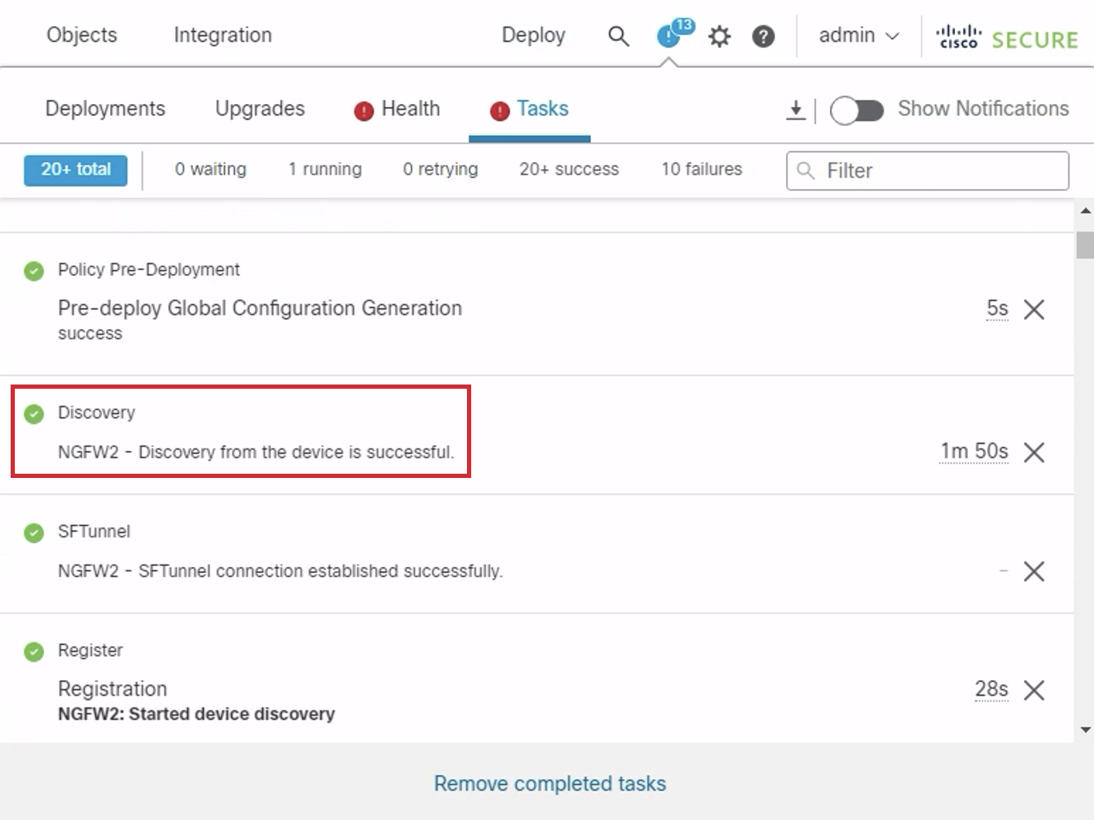
NOTE:
You can proceed to the next step after Discovery and Policy Deployment is complete.
Task 3 - Enabling License in NGFW1 and NGFW2
NOTE:
Before you begin this task, ensure that the Registration and initial Policy Deployment of both NGFW1 and NGFW2 are complete.
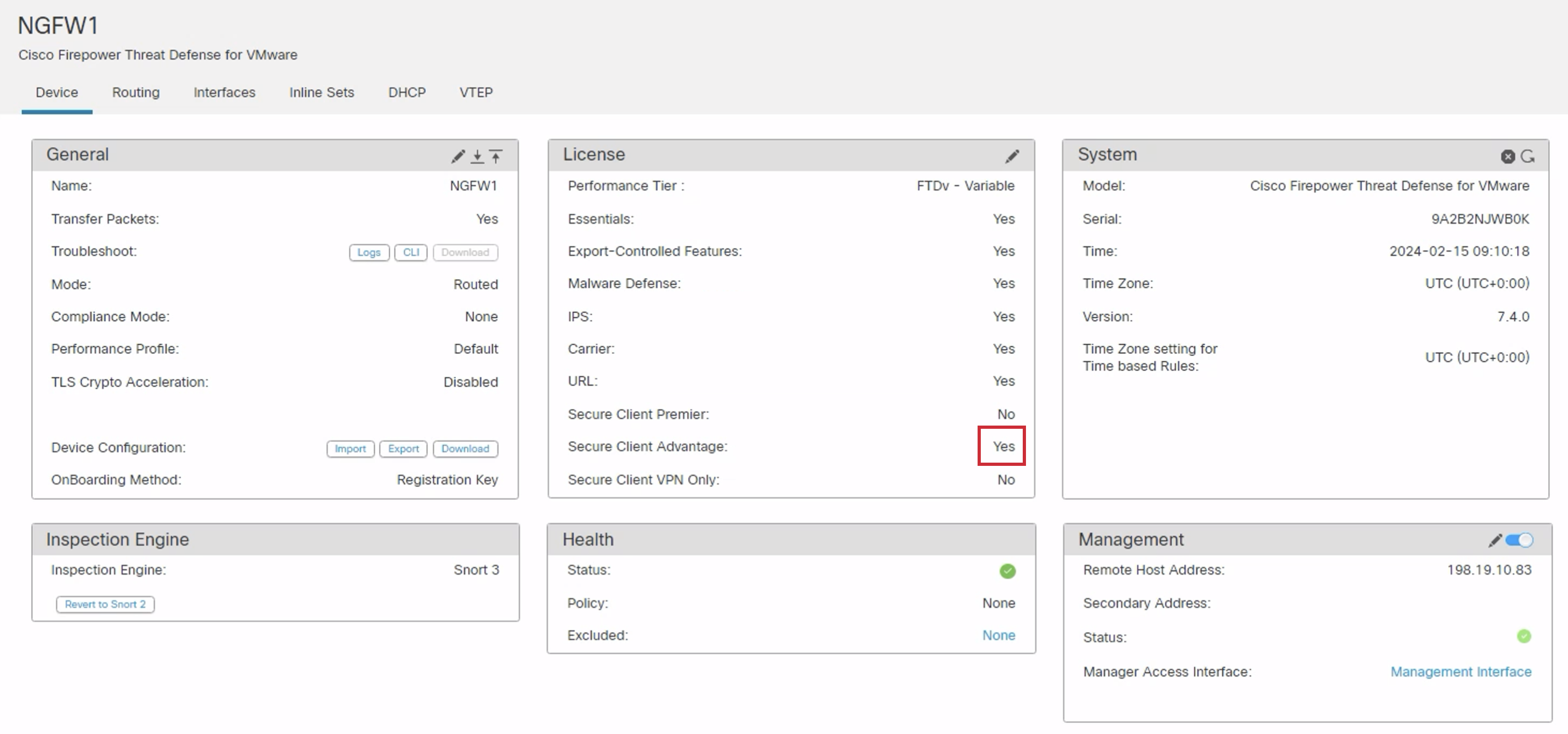
- Click the pencil icon in the NGFW1 row.

- In the new window, select the Device tab within NGFW1 and click the pencil icon to the right of the License section to edit the device licenses.
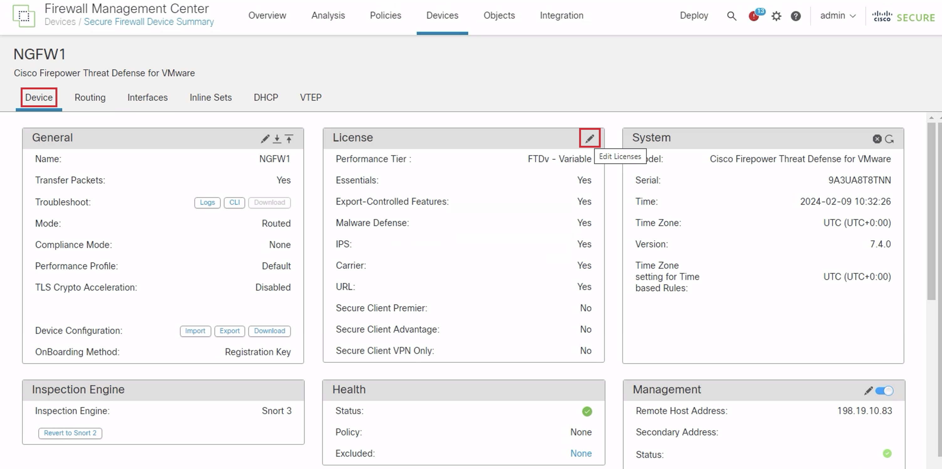
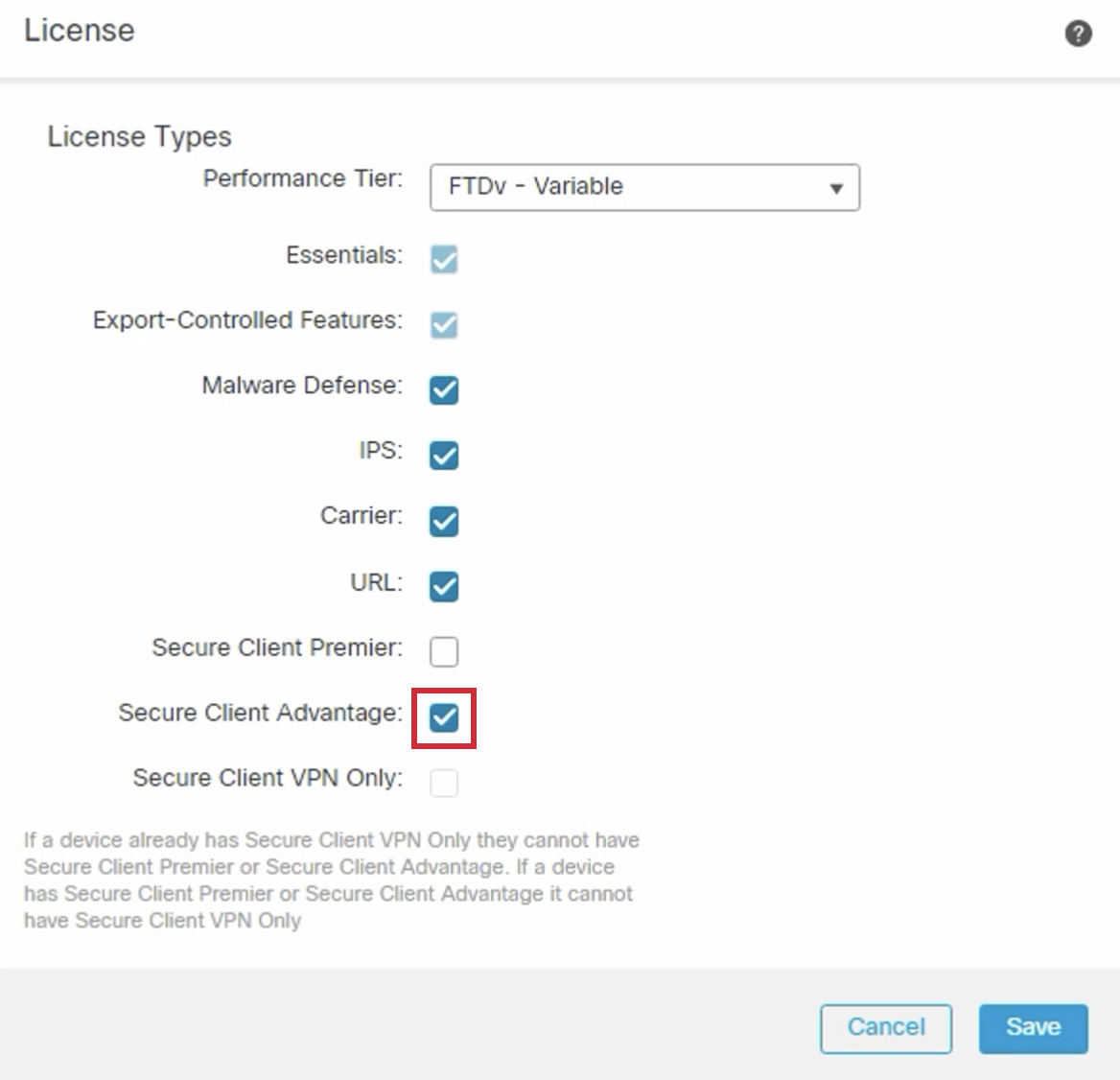
- Click the Secure Client Advantage checkbox in the License dialog box. Then click Save.
- Acknowledge the change by clicking OK.
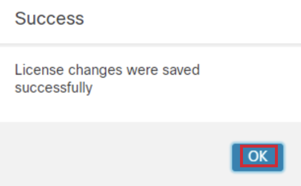
- A successful edit will look like this.
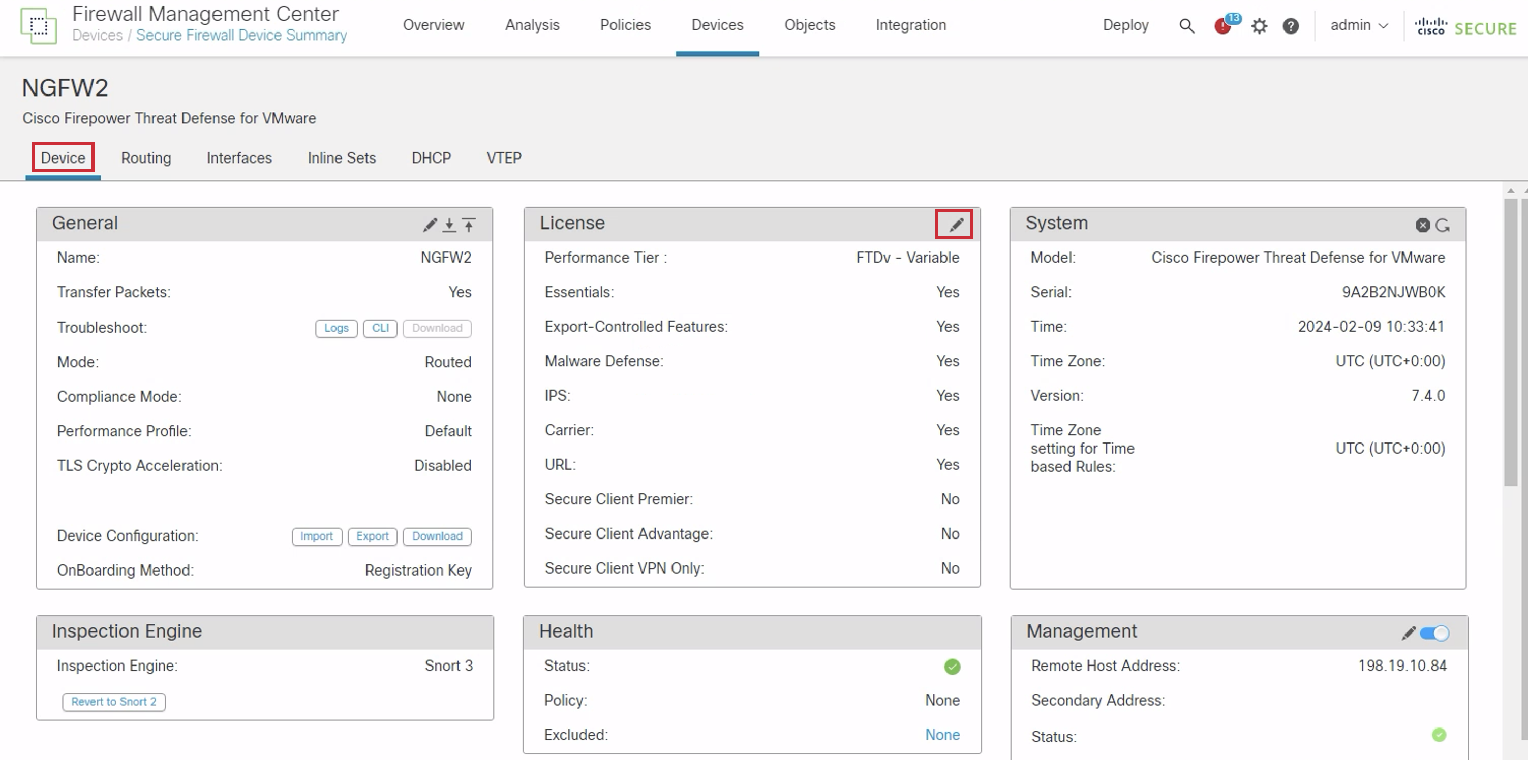
- Navigate back to Devices > Device Management, and click the pencil icon in the NGFW2 row.

- In the new window, select the Device tab within NGFW2 and click the pencil icon to the right of the License section to edit the device licenses.
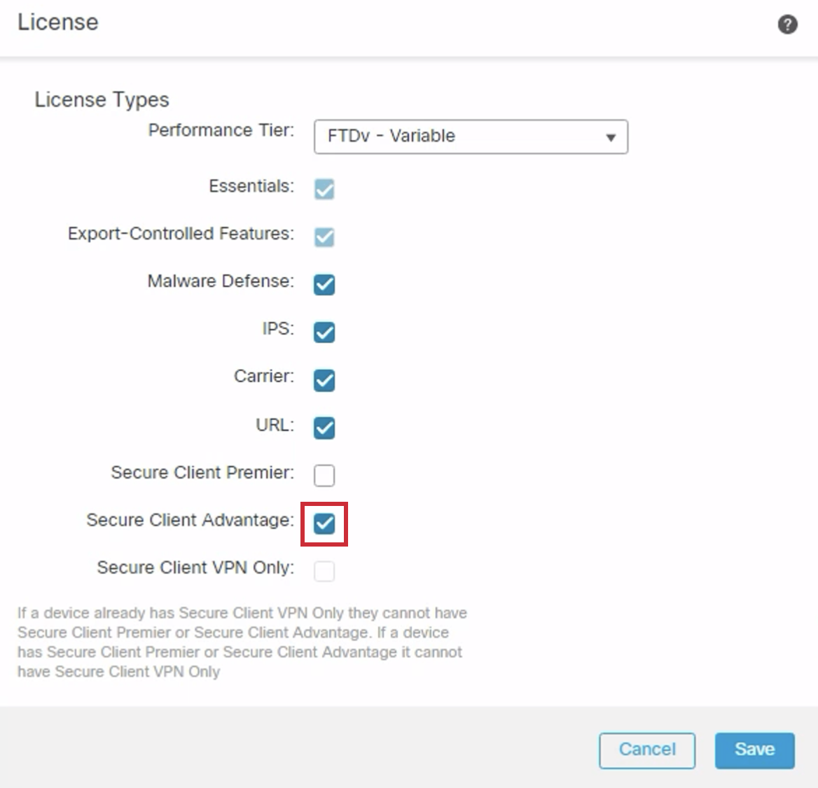
- Click the Secure Client Advantage checkbox in the License dialog box. Then click on Save.
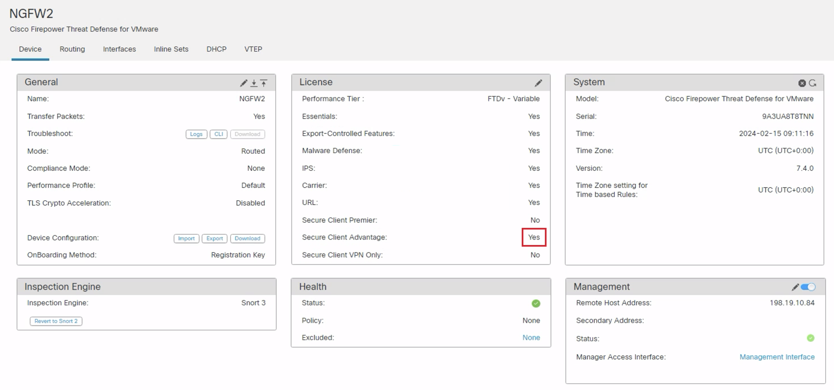
- Acknowledge the change by clicking OK.

- A successful edit will look like this.
Task 4: Configuring NGFW1
Step 1: Interface and Route Configuration of NGFW1
- Navigate back to Devices > Device Management and click on the pencil icon in the NGFW1 row.

- Click the 'Pencil' icon in the GigabitEthernet0/0 row to make changes to the interface.

Configure the interface as outlined below:
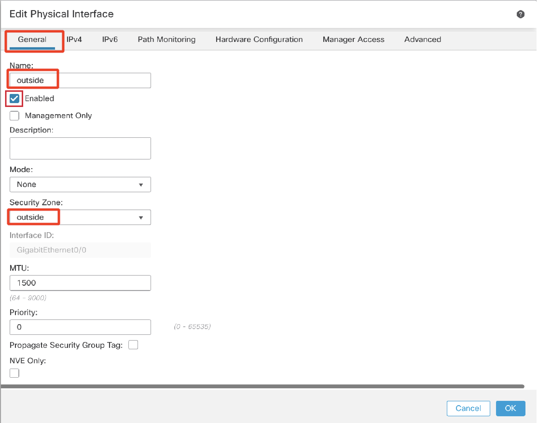
Under the General tab:
- Name: outside
- Click the Enabled check box.
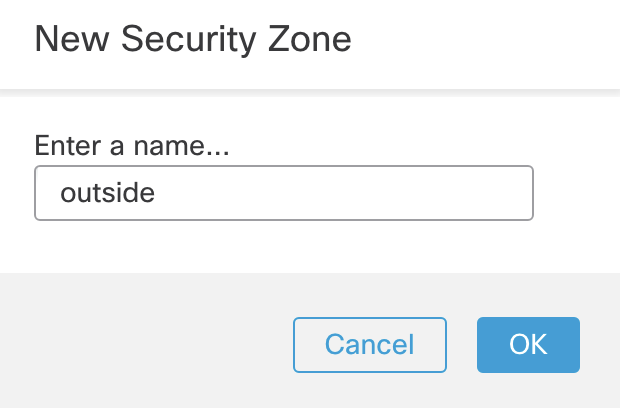
- Security Zone: Select "New..." from the drop down
- Type in 'outside' and click OK.
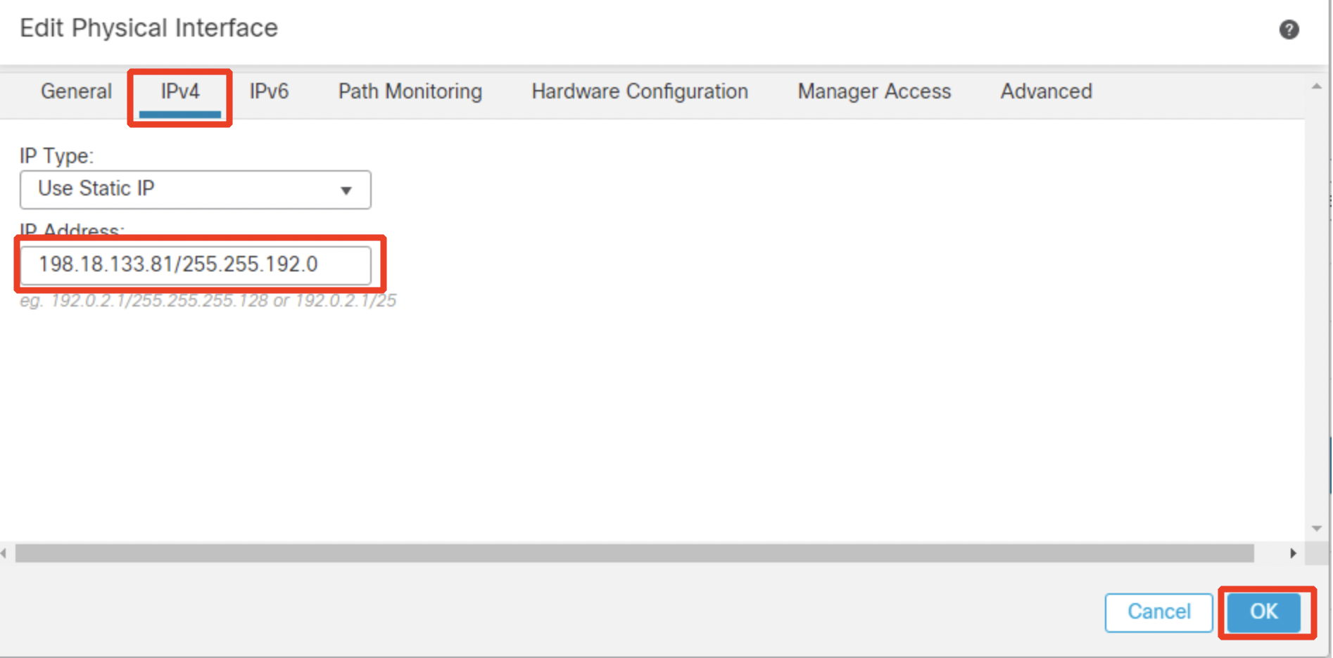
Under the IPv4 tab:
- IP Address: 198.18.133.81/255.255.192.0
- Click OK.
- Confirm the NGFW1 interface matches the image below. Then, click the 'Pencil' icon in the GigabitEthernet0/1 row to make changes to the interface.

Configure the interface as below:
Under the General tab:
- Name: inside
- Click the Enabled check box.
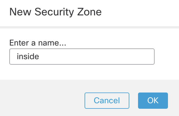
- Security Zone: Select "New..." from the dropdown
- Type in 'inside' and click OK.
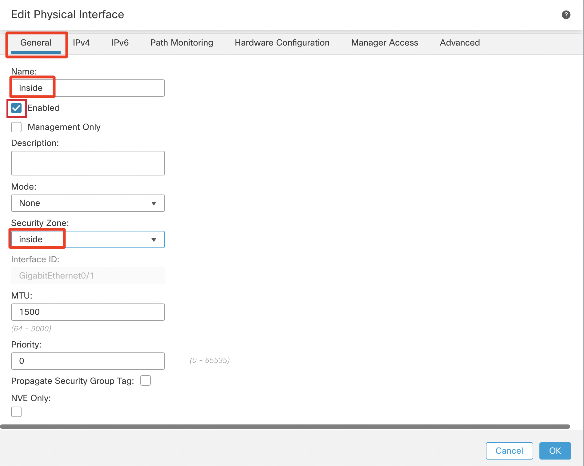
Under the IPv4 tab:
- IP Address: 198.19.10.1/255.255.255.0
- Click OK.
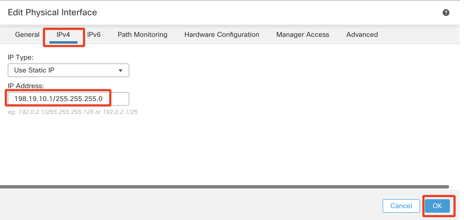
- Click Save. The final view of the Interfaces page should match the image below.

- Click the Routing tab. Select Static Route in the page tree, then Add Route off to the right to add a default route (This route is for Internet access that is required for the AttackIQ test).

- Configure the below:
- Interface : outside
- Available Network : any-ipv4 . Click Add.
- Gateway : 198.18.128.1
- Click OK.
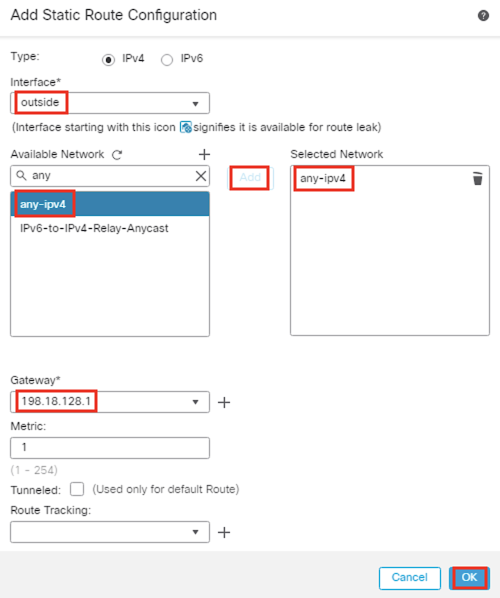
- Ensure the IPv4 route has populated, then click Save.

Step 2: Network Address Translation (NAT) Policy Configuration of NGFW1
For NAT Policy, we want to translate all the inside interface traffic destined for the internet from various source addresses, to the outside interface IP address. To do this, we will add a rule.
- Go to Devices > NAT. Click New Policy > Select Threat Defense NAT.

- Configure the Name as NGFW1-NAT. Select NGFW1 under Available Devices. Click on Add to Policy. Click on Save.
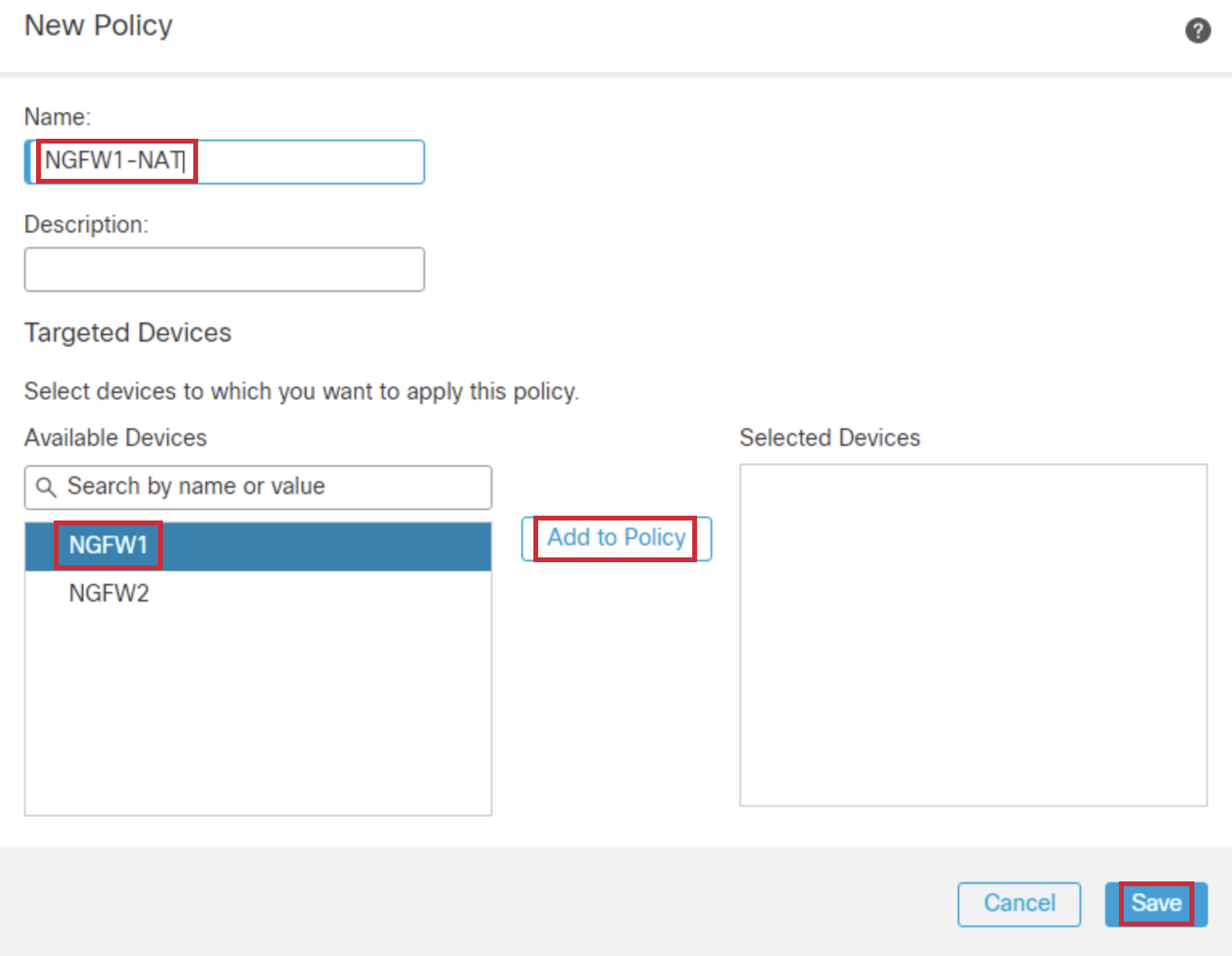
- A blank policy is created. Click Add Rule.

- Configure the policy as below:
- NAT Rule: Manual NAT Rule
- Type: Dynamic.
- Click theInterface Objects tab.
- Source Interface Objects : inside
Choose the inside object from Available Interface Objects and Click Add to Source. - Destination Interface Objects : outside
Choose the outside object from Available Interface Objects and Click Add to Destination.
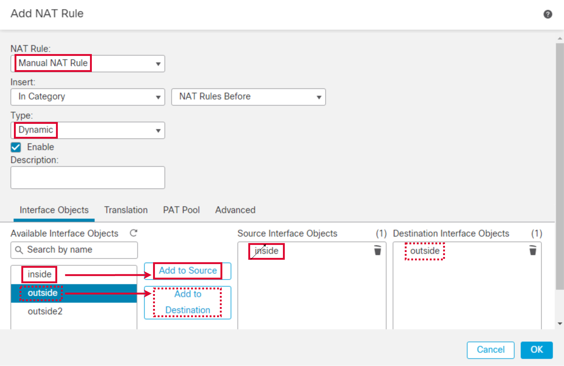
- Go to Translation tab. Click the + icon next to Original Source to create a new network object. Click + Add Object.
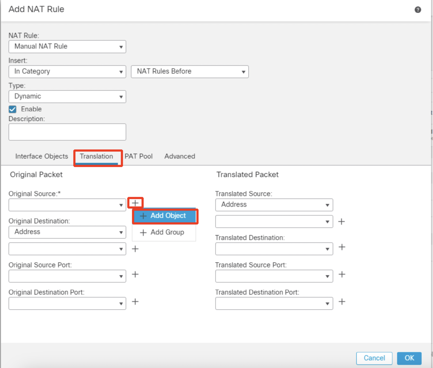
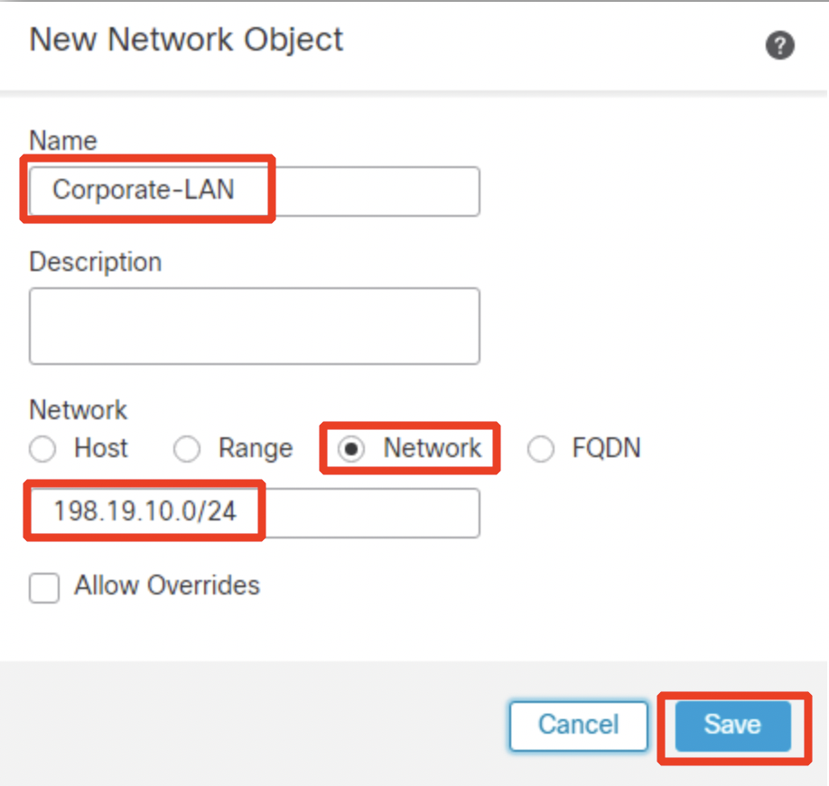
- Configure the network object as follows:
- Name: Corporate-LAN
- Network: Select the radio button Network and type in 198.19.10.0/24.
- Click Save.
- Select Destination Interface IP from the Translated Source drop down.
- Click OK.
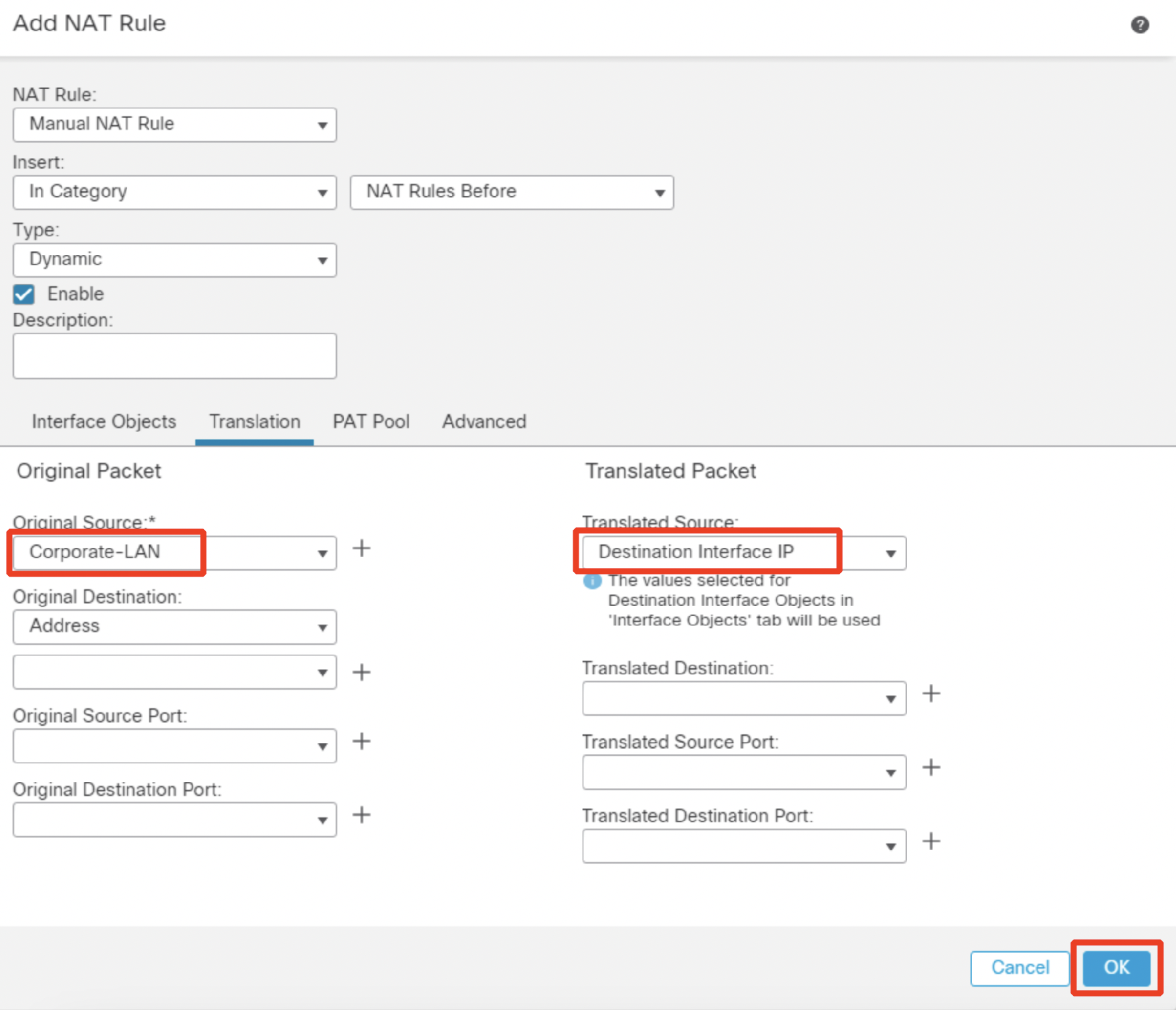
- Click Save.
Step 3: Access Control Policy (ACP) Configuration of NGFW1
Now we'll create a blank policy that has one 'Allow All' rule. This rule has no security protections attached and whitelists everything through the firewall.
NOTE:
Having a blank policy with an 'Allow All' rule is not a recommended practice. This is solely configured for testing purposes to demonstrate the Attack IQ test.
- Go to Policies > Access Control. Click the pencil icon in the NGFW1 Firewall Policy row.

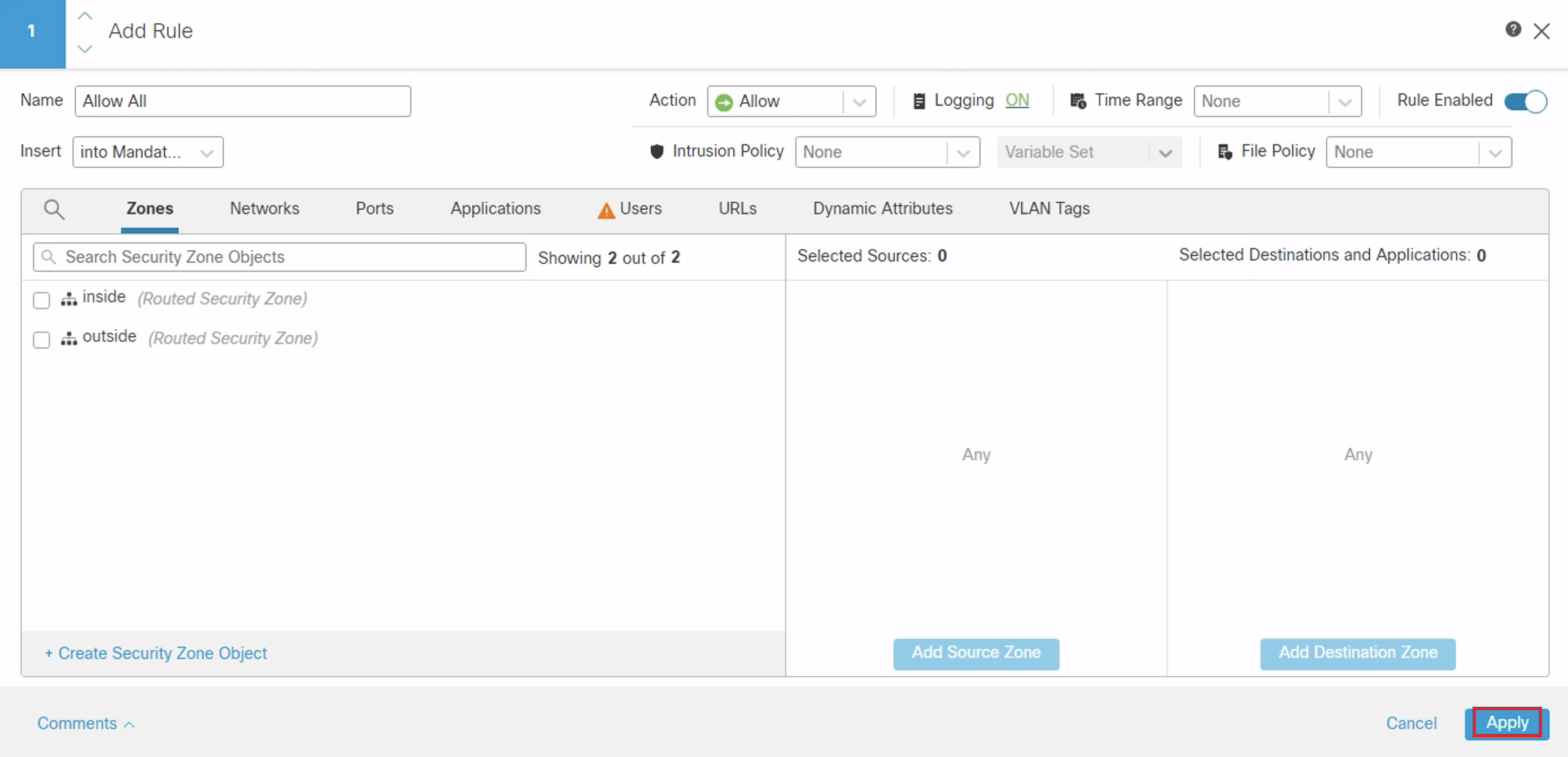
- Click on Add Rule. Configure the Name as 'Allow All'. Click on Logging.

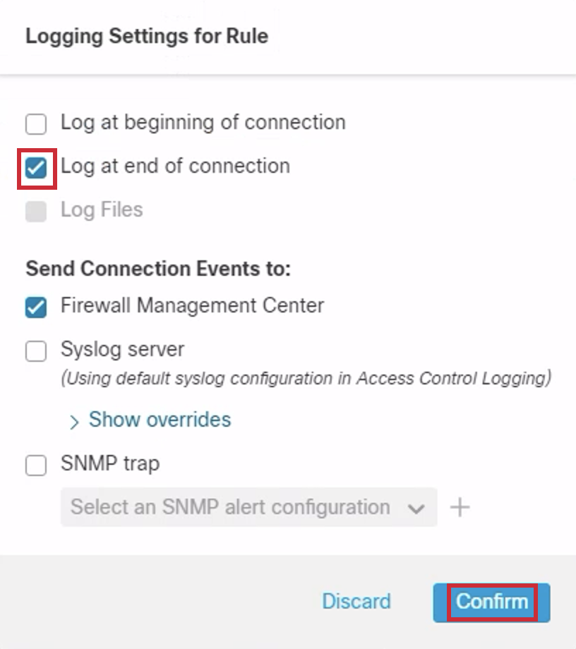
- Click on Log at end of connection > Confirm.
- Click Apply.
- Ensure the Access Control Policy is in place, then click Save.

Task 5 - Configuring NGFW2
Step 1: Interface and Route Configuration of NGFW2
- Navigate back to Devices > Device Management and click on the pencil icon next to NGFW2.

- Click the 'Edit' icon of GigabitEthernet0/0.

Configure the interface as below:
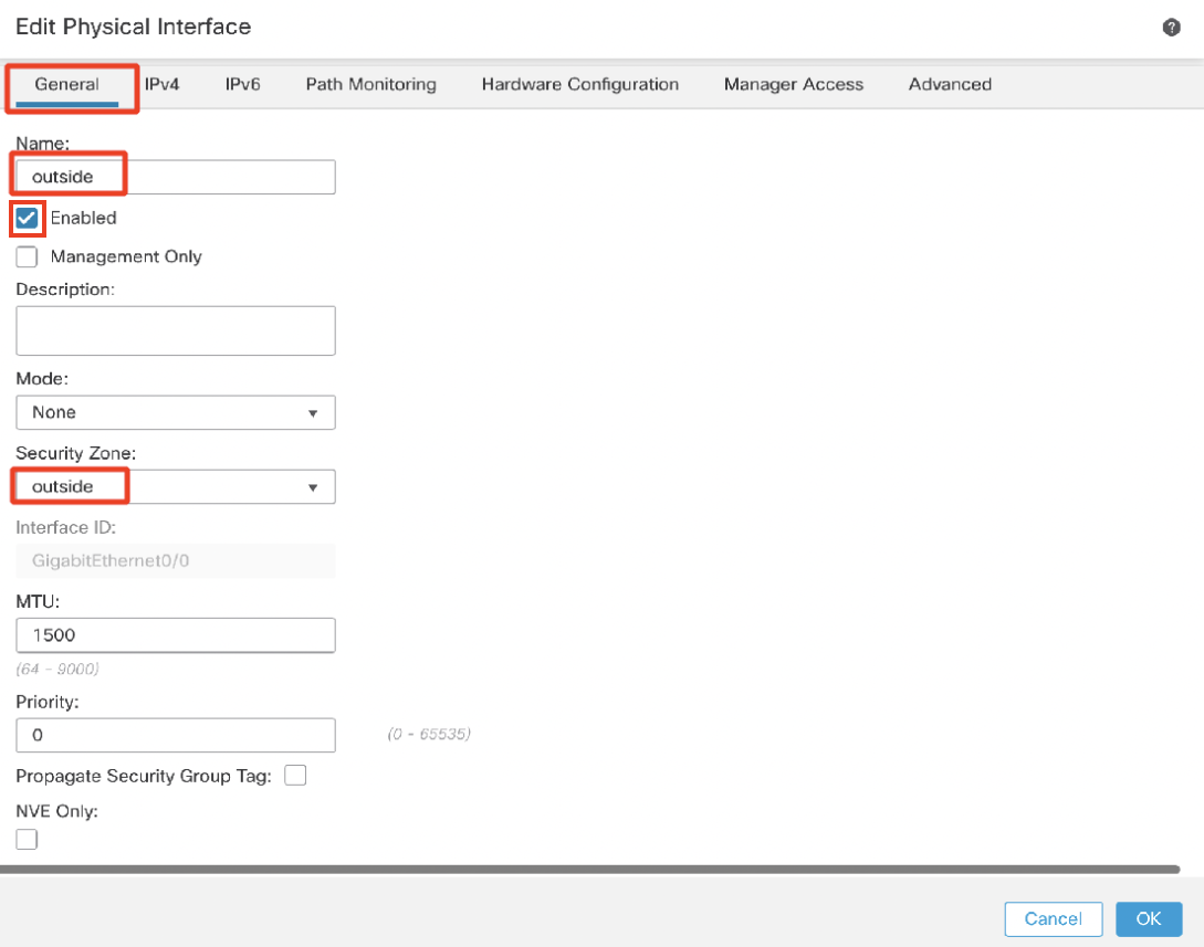
Under the General tab:
- Name: outside
- Click the Enabled check box
- Security Zone: outside
Under the IPv4 tab:
- IP Address: 198.18.6.1/24
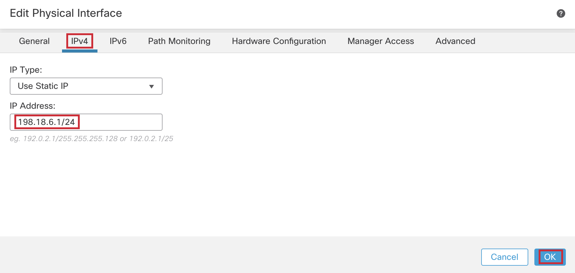
Click OK.
- Similarly, click the 'pencil' icon of GigabitEthernet0/1

Configure the interface as below:
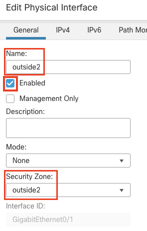
Under the General tab:
- Name: outside2
- Click the Enabled check box
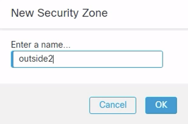
- Security Zone: Click New... to add a new zone named "outside2" and select this zone
Under the IPv4 tab:
- IP Address: 198.18.7.1/24
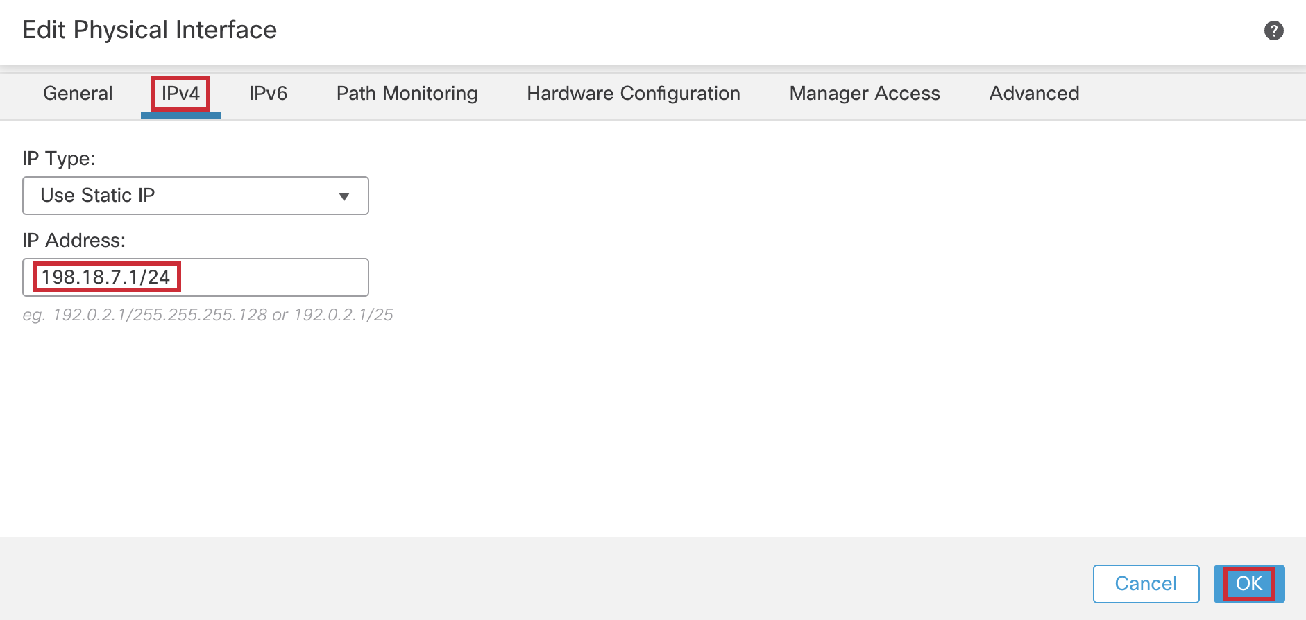
Click OK.
- Next, click on the 'pencil' icon of GigabitEthernet0/2

Configure the interface as below:
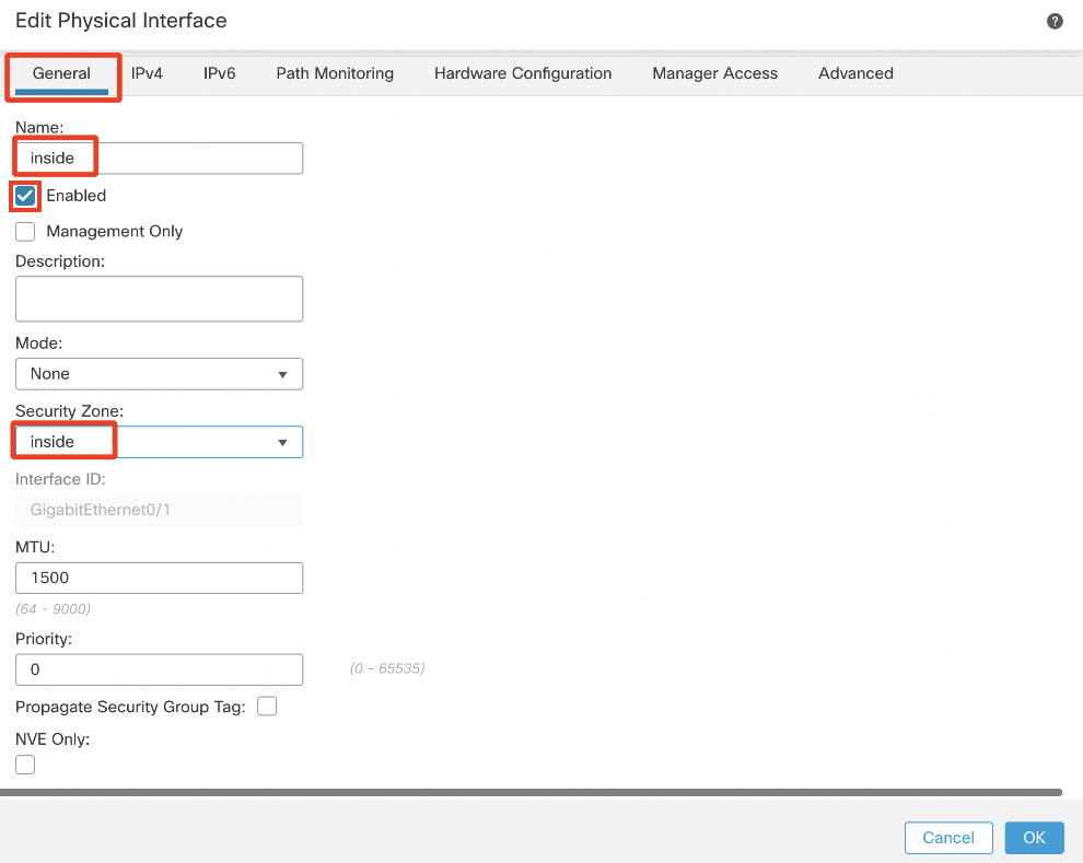
Under the General tab:
- Name: inside
- Click the Enabled check box
- Security Zone: inside
Under the IPv4 tab:
- IP Address: 198.18.8.1/24
Click OK.
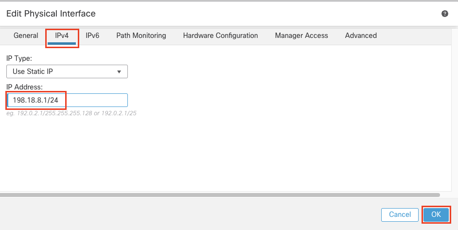
Click Save. The final view of the Interfaces page should be as below.

- Click the Routing tab. Click Static Route from the page tree, then Add Route to the right.
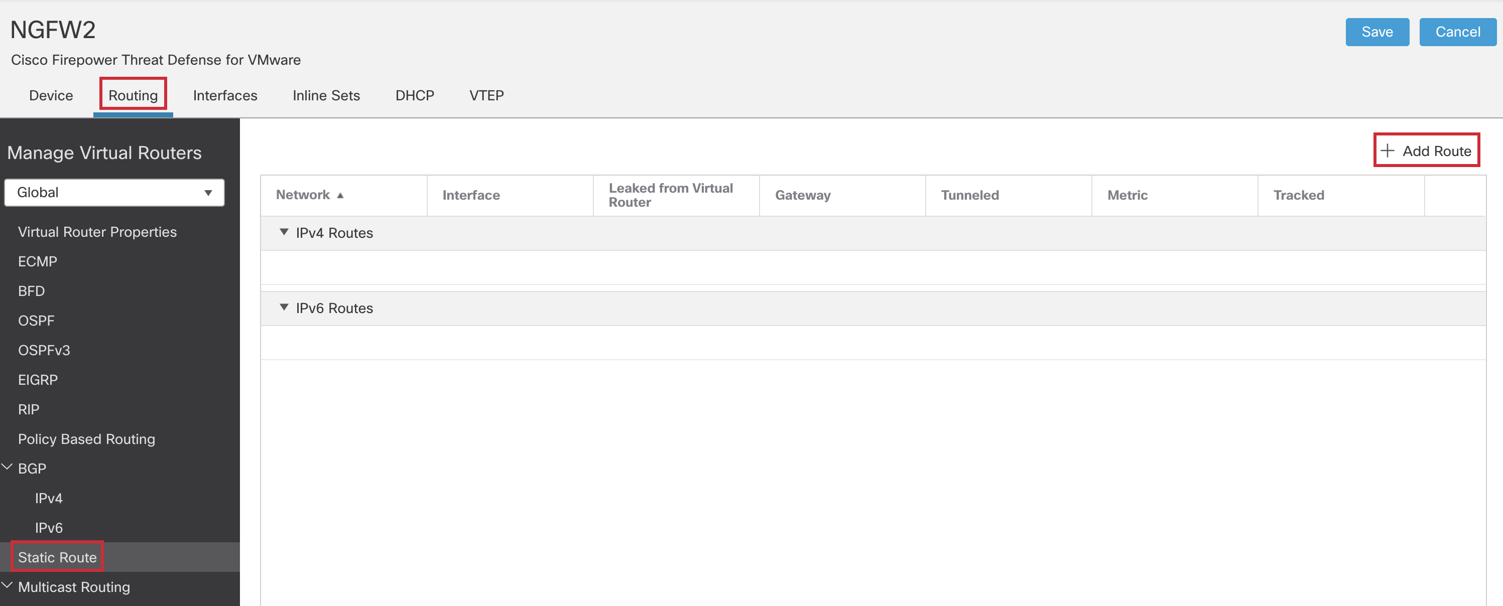
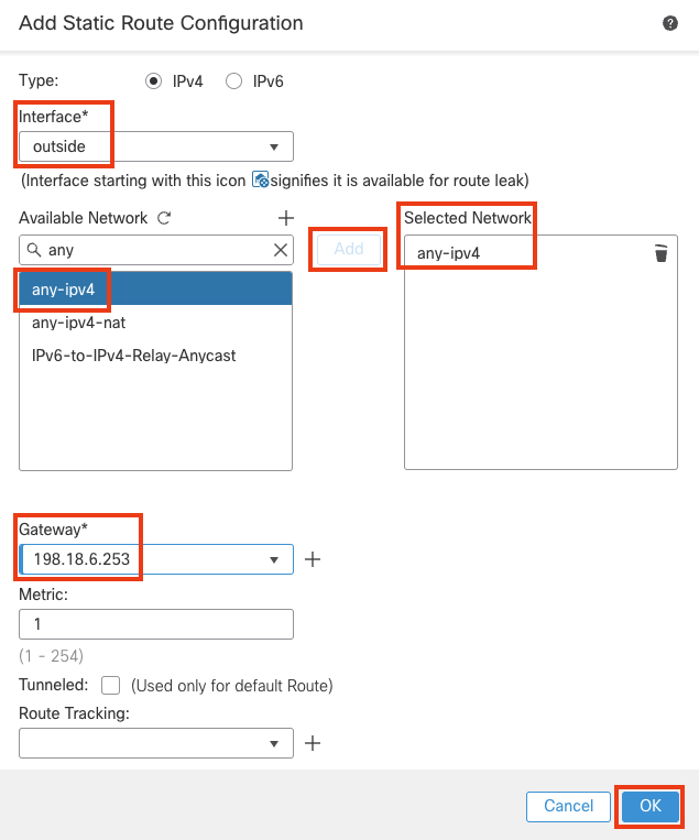
- Configure the below:
- Interface : outside
- Available Network : any-ipv4 . Click on Add.
- Gateway : 198.18.6.253
Click OK.
- Click Add Route to add another route.
- Configure the route as follows:
- Interface: outside2
- Available Network : any-ipv4 . Click on Add
- Gateway: 198.18.7.253
- Metric: 10
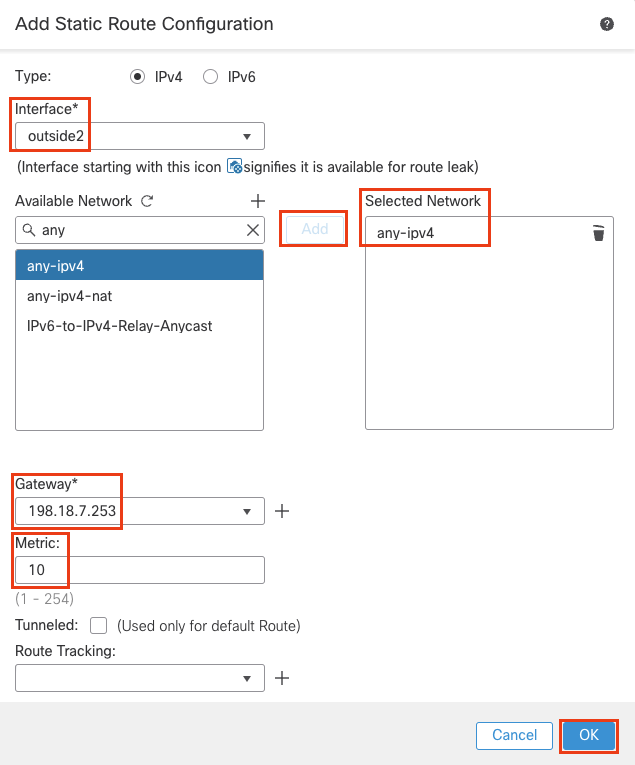
Warning
Verify that you have changed the metric value from 1 to 10.
- Click Save.

Step 2: Platform Settings Configuration of NGFW2
In the upcoming Policy Based Routing lab, we'll be setting Trusted DNS Servers in the platform settings. To do that let's set up a Platform Settings Policy for NGFW2.
- Click Devices from the main menu ribbon at the top and then select Platform Settings.
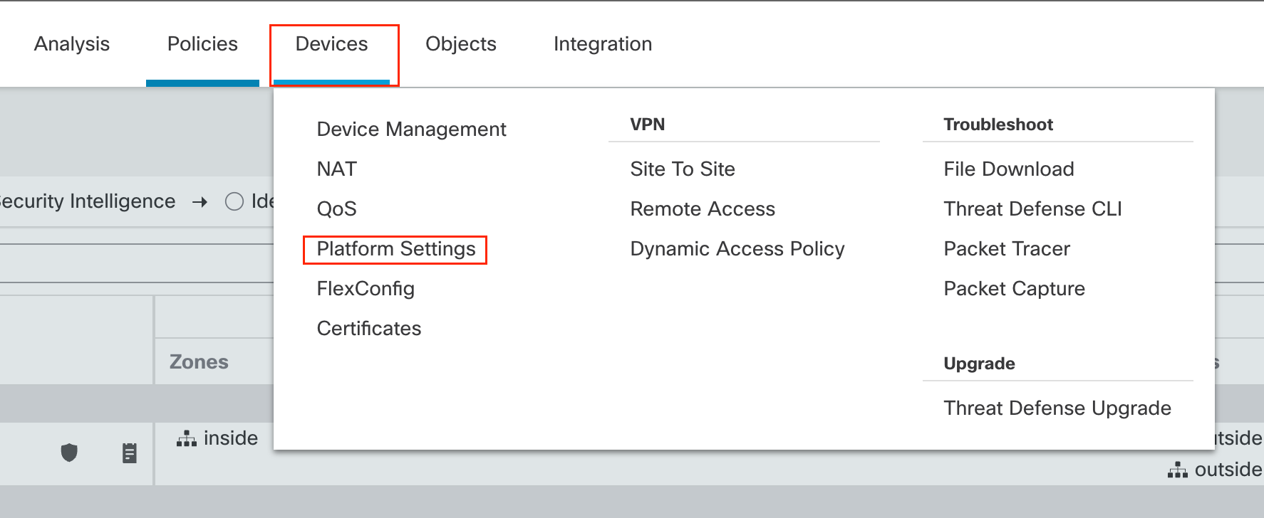
- Click New Policy and then select Threat Defense Settings.

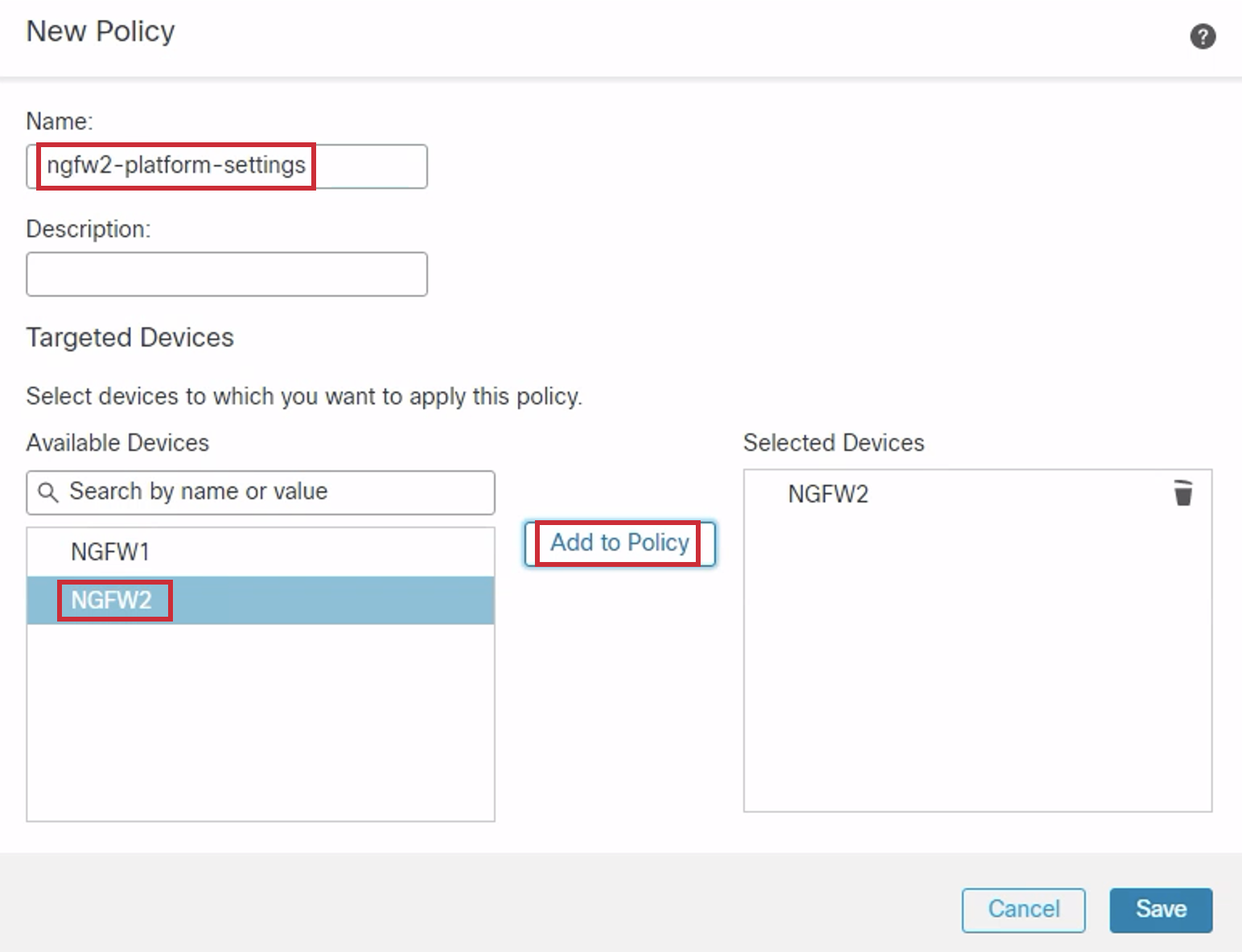
- Enter the Name as ngfw2-platform-settings.
- Choose NGFW2 from the Available Devices list and Click Add to Policy to add it to the Selected Devices list.
- Click Save. You might get a Warning. Click Yes.
- Now we'll configure the DNS settings.
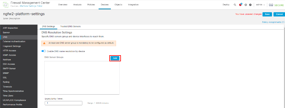
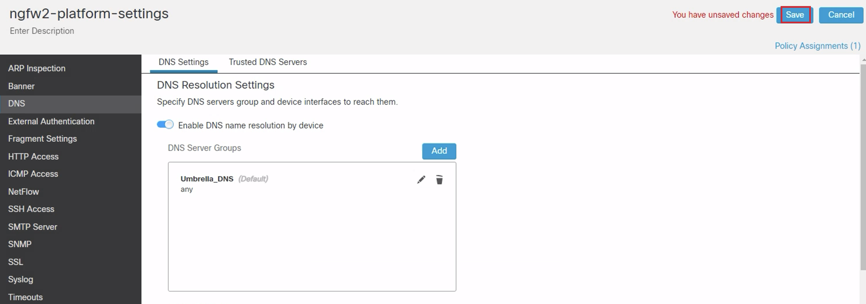
- Click DNS in the page tree. Then toggle Enable DNS name resolution by device
- Click Add next to DNS Server Groups.
- Click the + icon next to New Group in the configuration pop up.
- Enter Umbrella_DNS for name and 208.67.222.222,208.67.220.220 for DNS Servers.
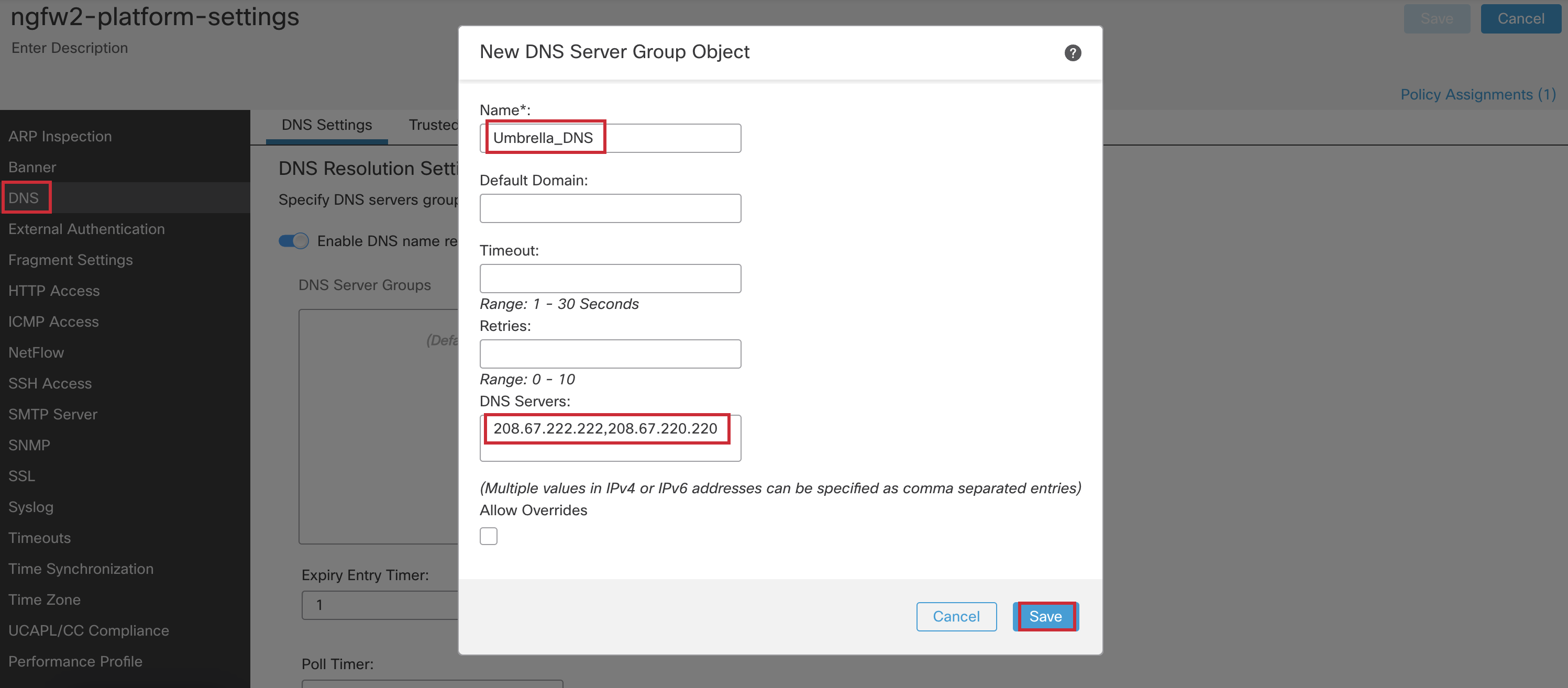
- Click Save.
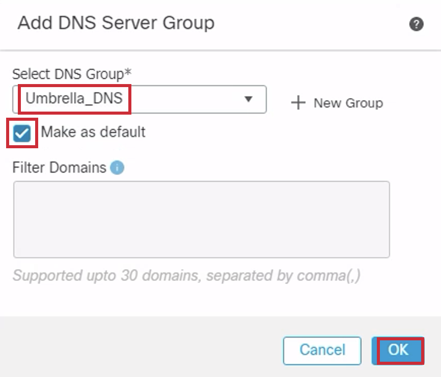
- Select Umbrella_DNS from the DNS Group drop-down list. Select Make as Default. Click Ok.
- Click Save.
Step 3: Network Address Translation (NAT) Policy Configuration of NGFW2
For NAT Policy, we want to translate all the inside interface traffic destined for the internet from various source addresses, to the outside interface IP address. To do this, we will add a rule.
- Go to Devices > NAT. Click New Policy > Threat Defense NAT.

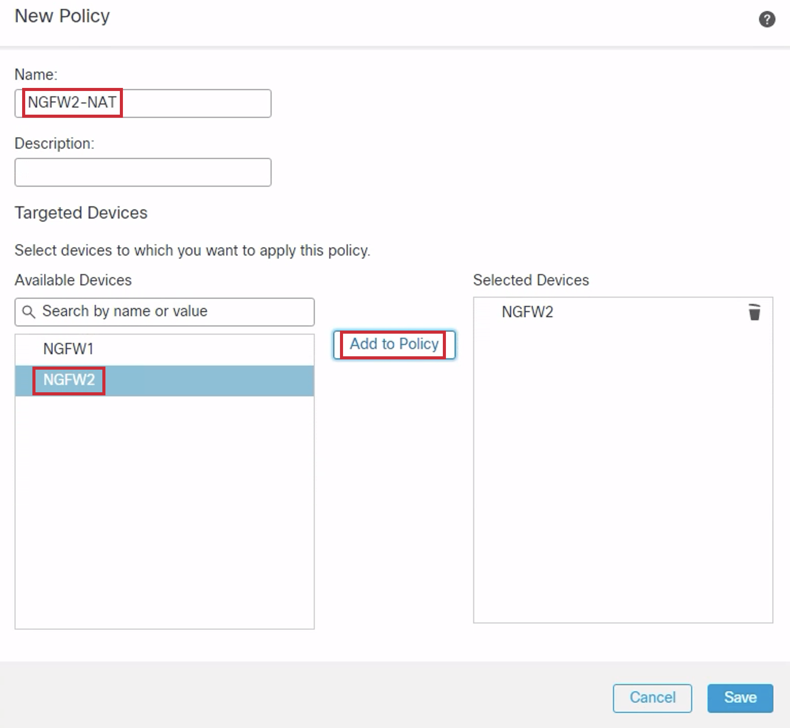
- Configure the Name as 'NGFW2-NAT'. Select NGFW2 under Available Devices. Click Add to Policy. Click Save.
- A blank policy is created. Click Add Rule.

- Configure the policy as below:
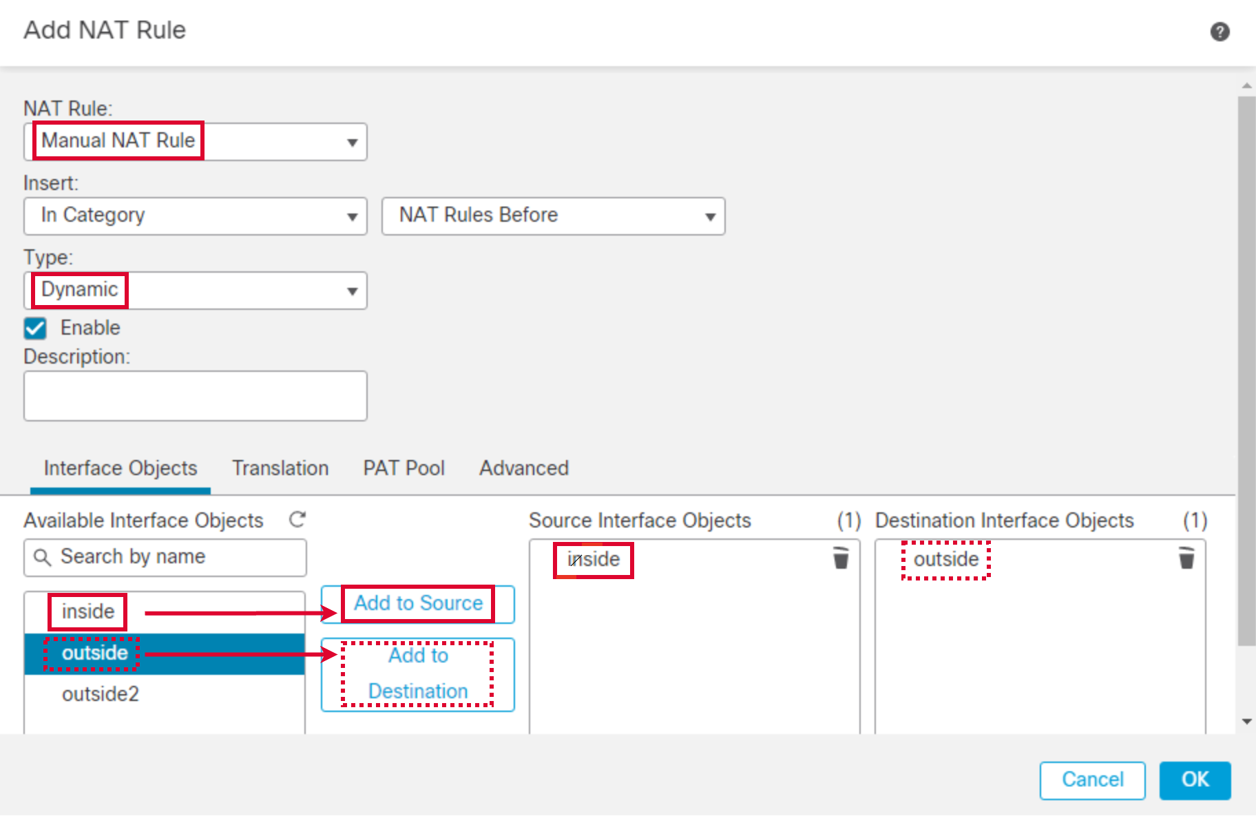
- NAT Rule: Manual NAT Rule
- Type: Dynamic. Click the Interface Objects tab.
- Source Interface Objects : inside
Choose the inside object from Available Interface Objects and Click on Add to Source. - Destination Interface Objects : outside
Choose the outside object from Available Interface Objects and Click on Add to Destination.
- Go to Translation tab. Configure as follows:
- Click on + next to Original Source. Click Add Object.
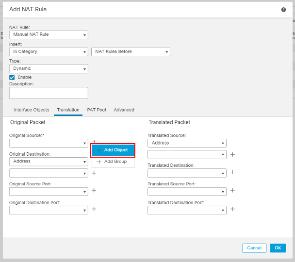
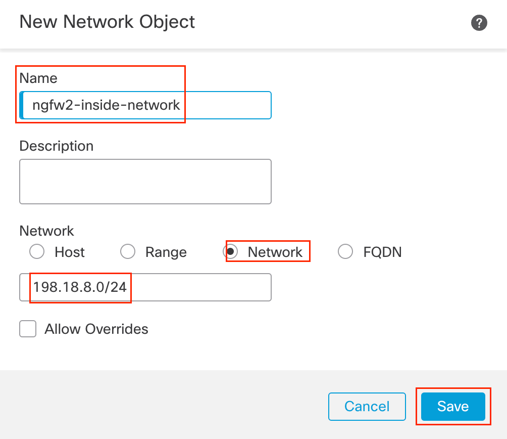
- In the pop-up box, configure the following details:
- Name: ngfw2-inside-network
- Select the Radio button next to Network
- In the text box below enter 198.18.8.0/24
- Click Save
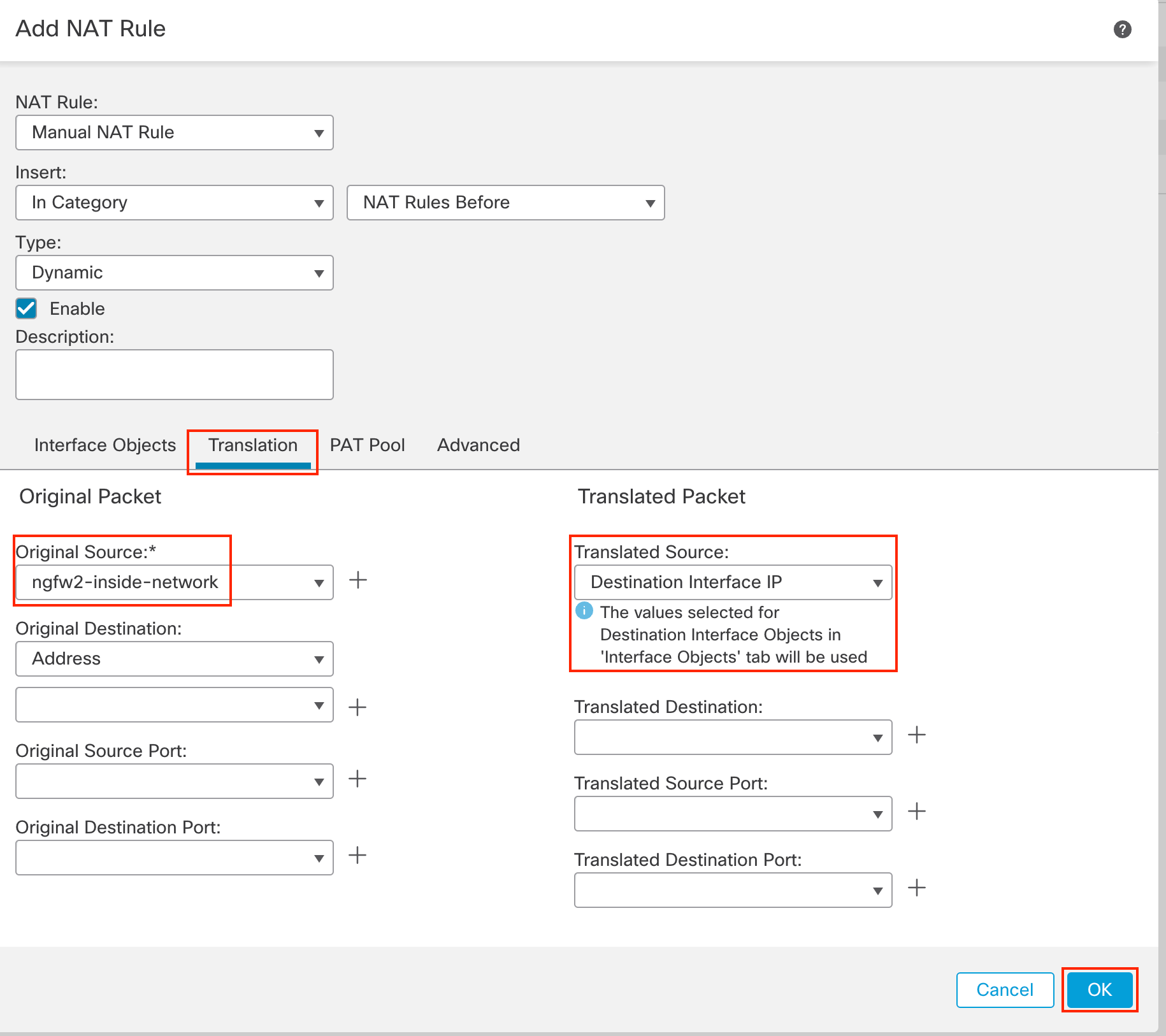
- Translated Source: Destination Interface IP
- Click OK.
- Click Add Rule to add another rule.

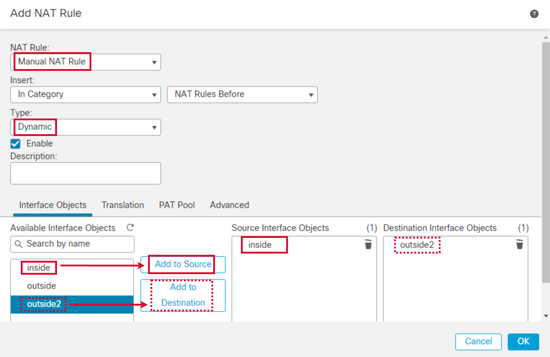
- Configure the policy as below:
- NAT Rule: Manual NAT Rule
- Type: Dynamic.
- Click the Interface Objects tab.
- Source Interface Objects : inside
Choose the inside object from Available Interface Objects and Click on Add to Source. - Destination Interface Objects : outside2
Choose the outside2 object from Available Interface Objects and Click on Add to Destination.
- Go to Translation tab. Configure as follows:
- Original Source: ngfw2-inside-network
- Translated Source: Destination Interface IP
- Click OK.

- Click Save.
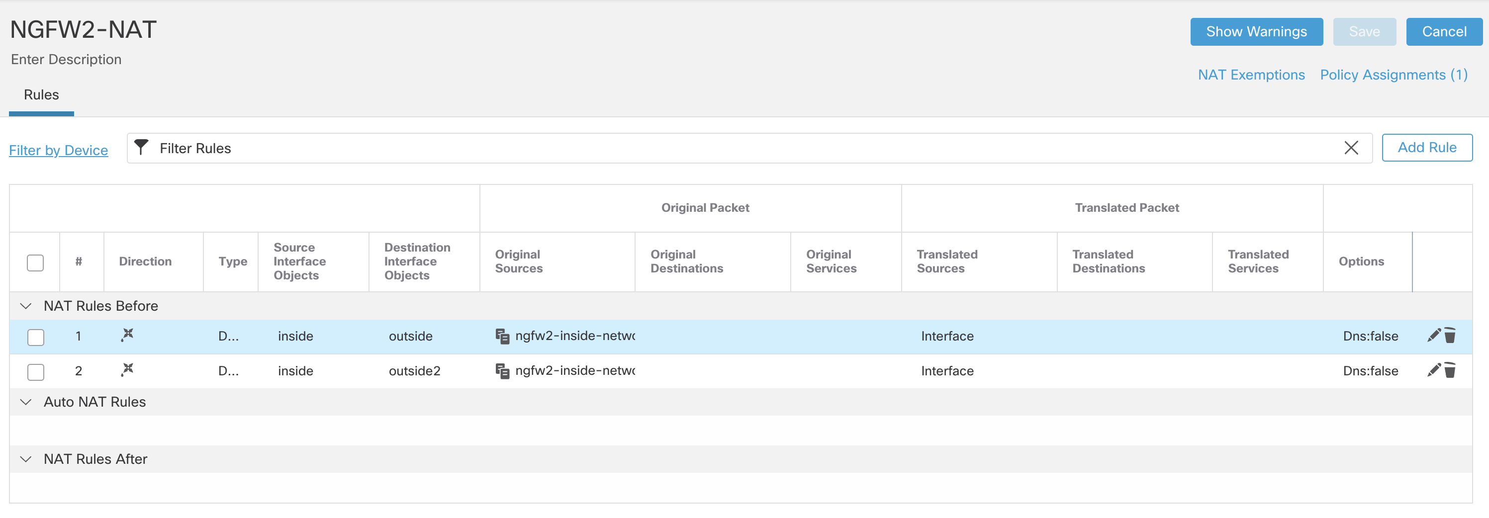
Step 4: Access Control Policy Configuration of NGFW2
- Go to Policies > Access Control. Click on the pencil icon next to NGFW2 Firewall Policy.

- Click Access Control in the policy selector. Click Add Rule, and configure the following rule:

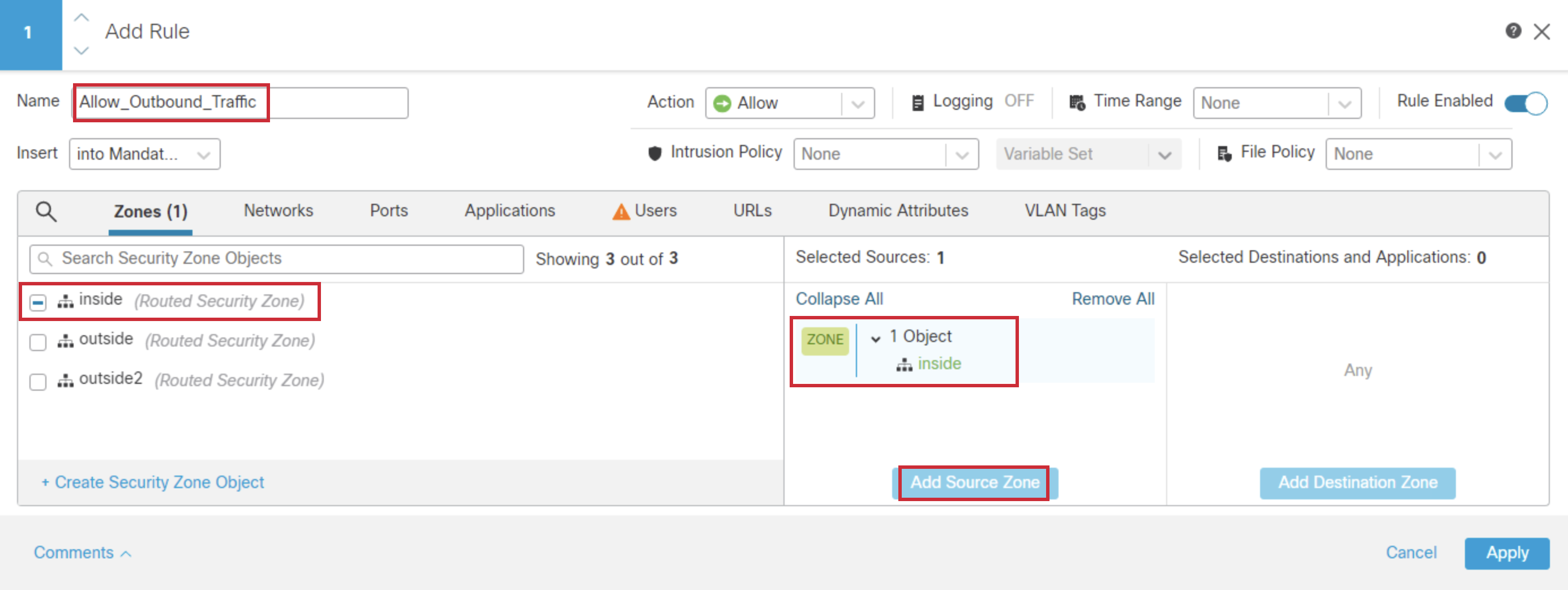
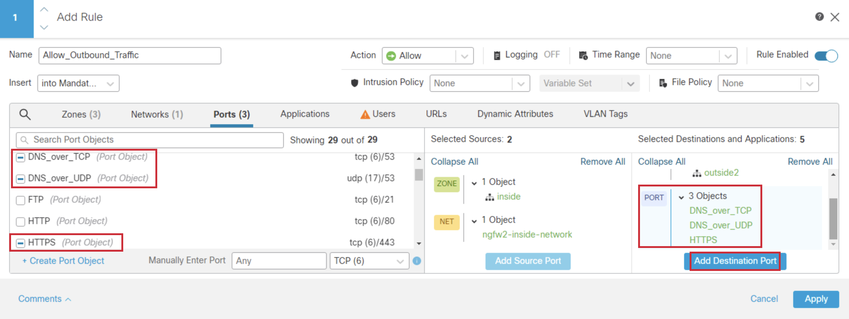
- Name: Allow_Outbound_Traffic
- Select inside from Zones and click Add Source Zone
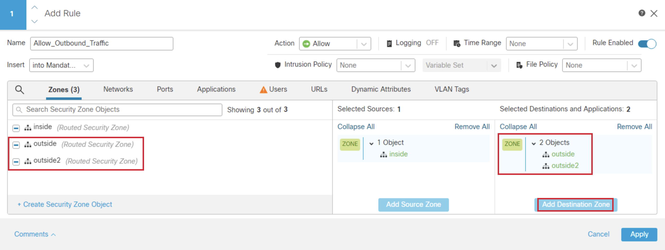
- Select outside and outside2, and click Add Destination Zone
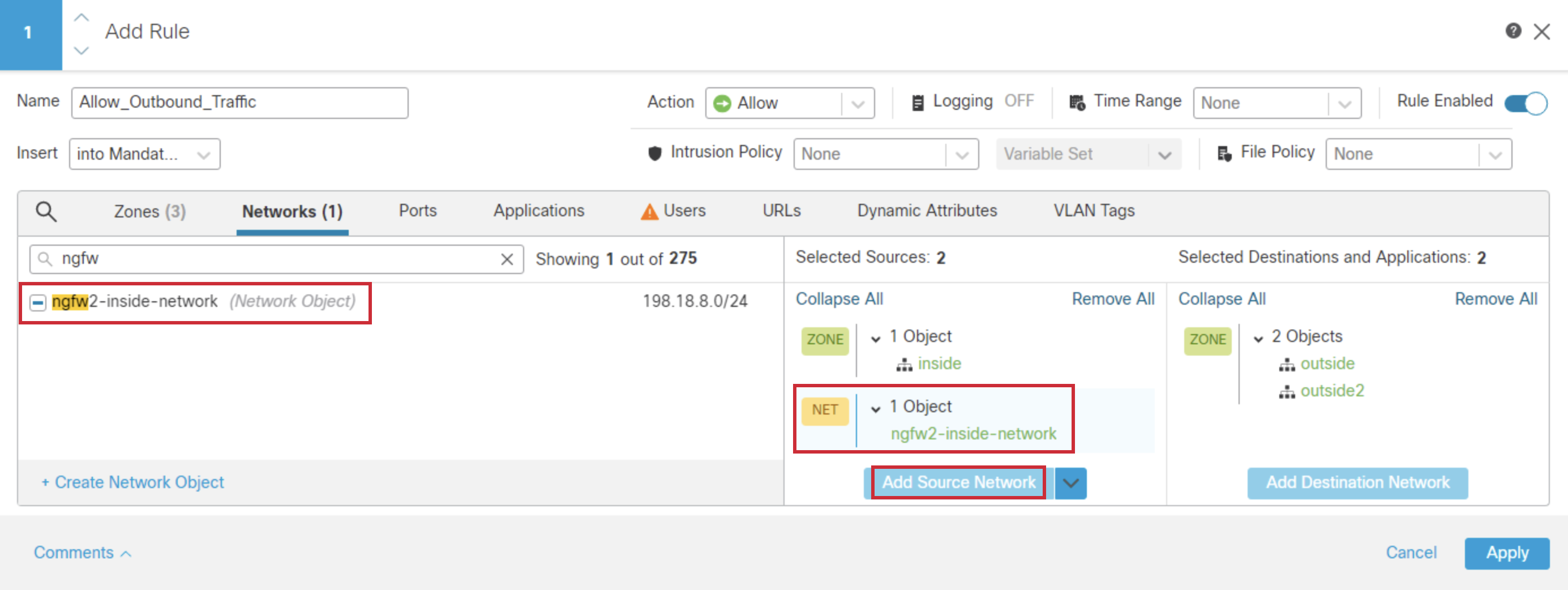
- Click the Networks tab, and search for ngfw2-inside-network. Select and click Add Source Network.
- In the Ports tab, Select the following objects:
- DNS_over_TCP
- DNS_over_UDP
- HTTPS
- Click on Add Destination Port
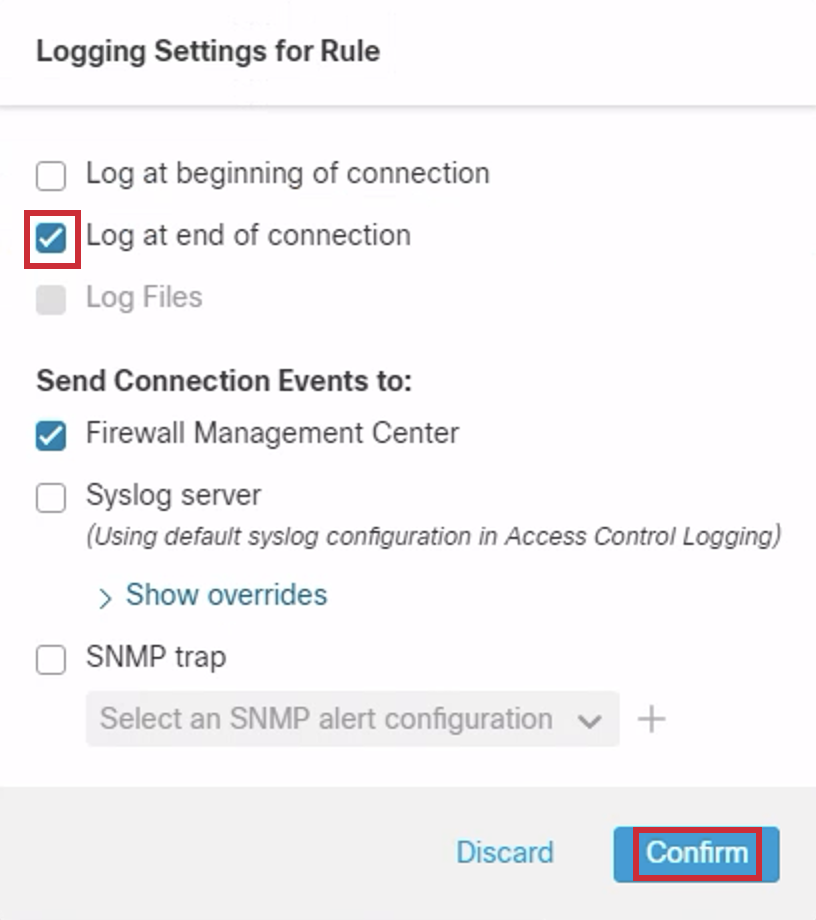
- Select Logging and in the popup select Log at end of connection and click Confirm. The destination for the Connection Events is automatically selected as Firewall Management Center. There are more capable logging settings available. However, for this lab, we are just enabling the Connection Events to be sent to the Firewall Management Center. Also, as part of best practices, we enabled logging only at the end of a connection.
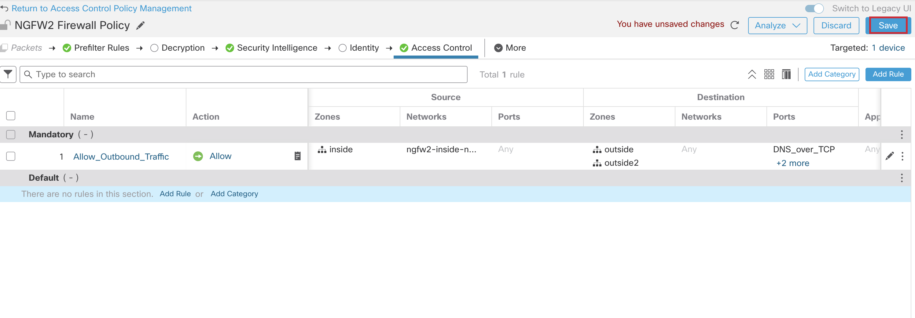
- Click Apply, and then click Save at the top, to save all the changes to the Access Control Policy configuration.
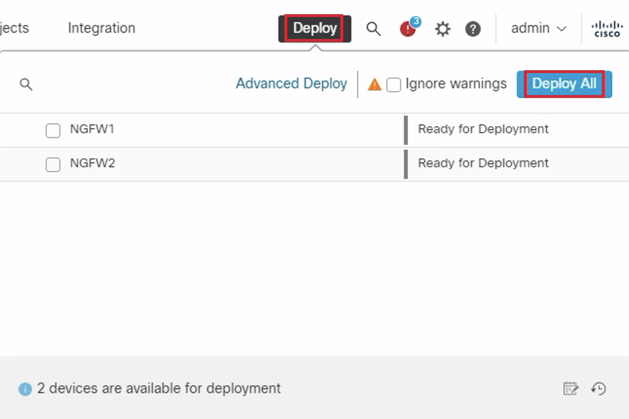
- Click Deploy. > Deploy All. Wait for the deployment to complete.
Warning
In the event you come across a 'Ignore warnings' checkbox during your deployment, please be sure to select it.
Success!
You have completed Device Onboarding. Please click the link below to move on to Preparing your 1010 for Customer Demos.
📚Additional Resources
For more information on how Access Control Policies are configured for Secure Firewall devices, please refer to the following document Access Control Policy
Updated over 1 year ago

