Firewall Roadshow Ignite - Preparing for Customer Demos
Cisco Internal Use Only for Secure Firewall Roadshow Ignite Event
Overview
Unlike previous labs where you configured virtual Threat Defense devices using virtual Firewall Management Center, this lab leverages cloud-delivered Firewall Management Center (cdFMC) to configure all the components of a Cisco Secure Firewall Threat Defense. It offers the same look, functionality, and workflow as on-premises and virtual versions of the Firewall Management Center thus removing any learning curve for existing customers and you can manage your firewall policies from anywhere in the world.
In this lab, we will resume the upgrade process from the Getting Started Guide and configure the Firewall 1010 to be used as a security appliance in your office/home network or for demo purposes. We will configure and validate interface , DHCP server for internal LAN users, NAT, Routing and Access Control Policy configuration so you can effectively demonstrate the security capabilities of Secure Firewall Threat Defense.
Topology
This guide uses the same topology that was used initially. The Firewall 1010 has Ethernet1/1 connected to the upstream switch for internet connectivity and Ethernet1/2 connected to their workstation.
The firewall is connected to cloud-delivered Firewall Management Center (cdFMC) hosted on the internet via Ethernet1/1.
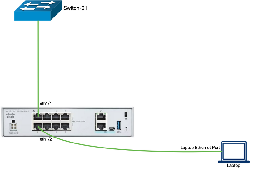
Network Topology
Lab Tasks Overview

Task 1. Finish the Upgrade Tasks
Note
If in case the upgrade fails, please notify your proctor and skip these upgrade steps. Proceed with Task 2 complete the configuration tasks.
In this section, we will review the upgrade status for the Firepower 1010 device to software release 7.4.2.
-
Verify the upgrade is successful by navigating to the Device Management page. Click Devices > Device Management.

Note
The above page will not be displayed until the copy of upgrade package to the device is completed. The time of completion for this step will vary based on the environment uplink. For entire Upgrade Process, please expect around 35 minutes for completion.
-
On the Device Management page, note the version near the center of the page and then click on the Upgrade tab.

-
On the Upgrade tab, note the path taken from 7.2.5 to 7.4.2.

-
Now the final step is to redeploy configurations to the device you just upgraded.
-
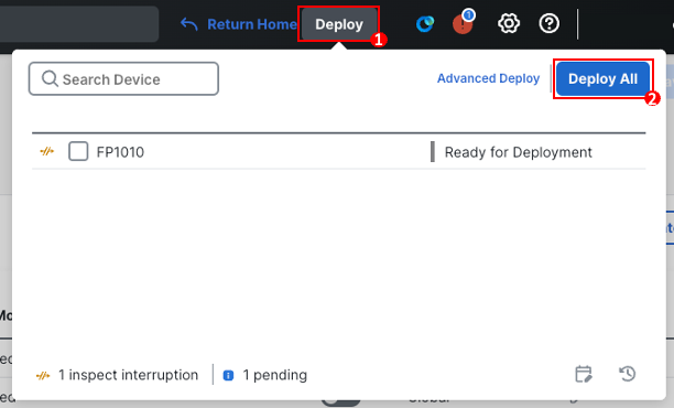
Click Deploy.
-
Click Deploy All.
-
Warning
Should you receive a warning during the deployment, click the checkbox next to Ignore Warnings and then click Deploy. This warning can be safely ignored.
- Verify deployment success before moving onto the next section.
Success
Your device is now upgraded to version 7.4.2 and you are ready to apply configuration to your device.
Task 2. Getting your Firewall ready for Customer Demo
Interface Configuration
In this step, we will validate the existing interface configuration and configure the additional interfaces required for users in LAN network to connect to the internet.
Note
By default the Ethernet 1/1 is set as Layer 3 interfaces whereas Ethernet1/2-Ethernet1/8 interfaces are set as Layer 2 switchports and are assigned to the VLAN1.
-
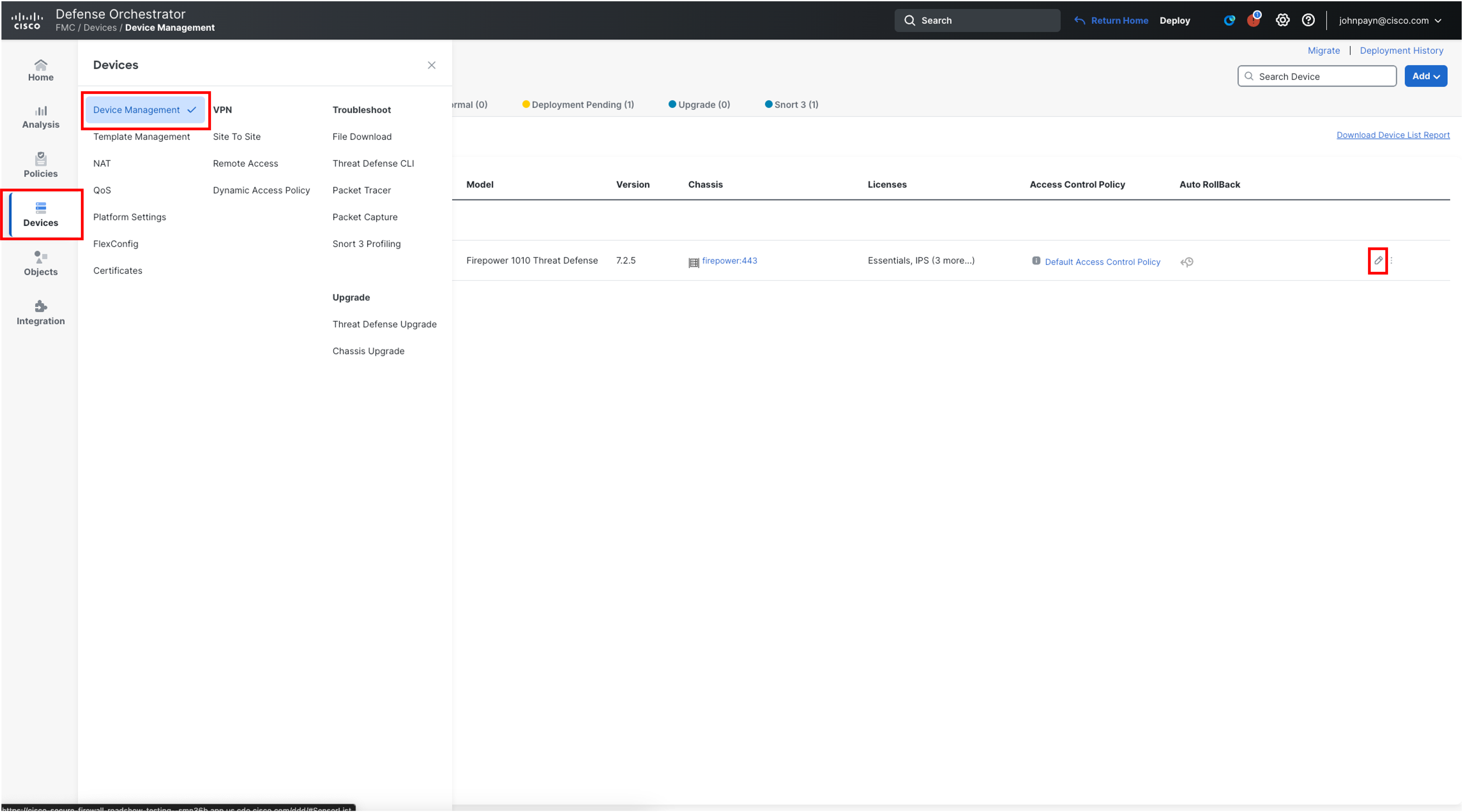
From your cdFMC tenant, navigate to Device > Device Management. On the far right side of the page, for the Firewall 1010 FP1010, click on the pencil icon to edit interface configuration.
-
Click on the pencil icon on the far right of Ethernet1/1 to edit the interface configuration
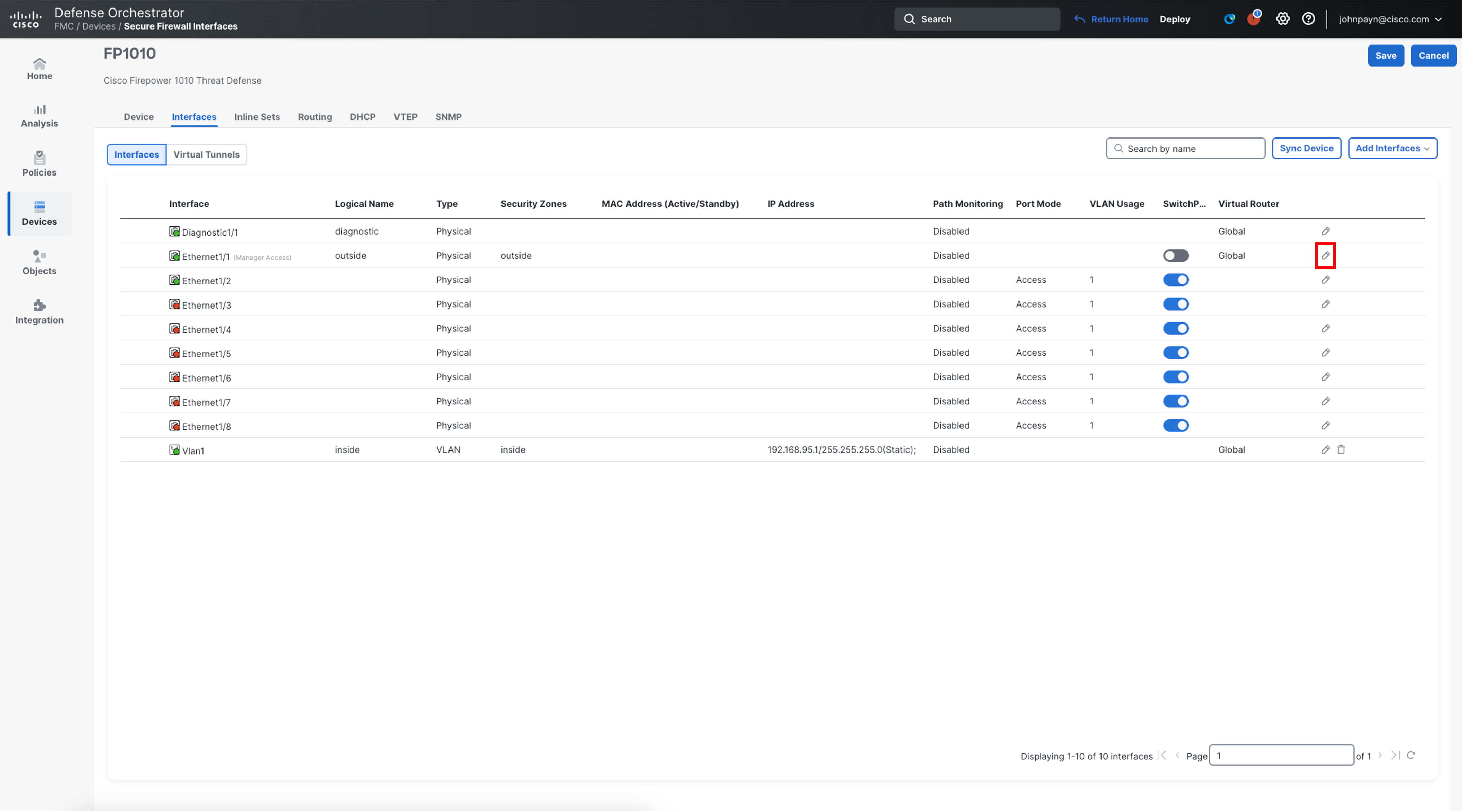
-
Click Manager Access tab within interface configuration and ensure that the Ethernet1/1is enabled with Enable management access as this interface is being used for device onboarding and registration to cdFMC.
IMPORTANT
DO NOT UNCHECK Enable management access as Firewall 1010 will lose connection to cdFMC.
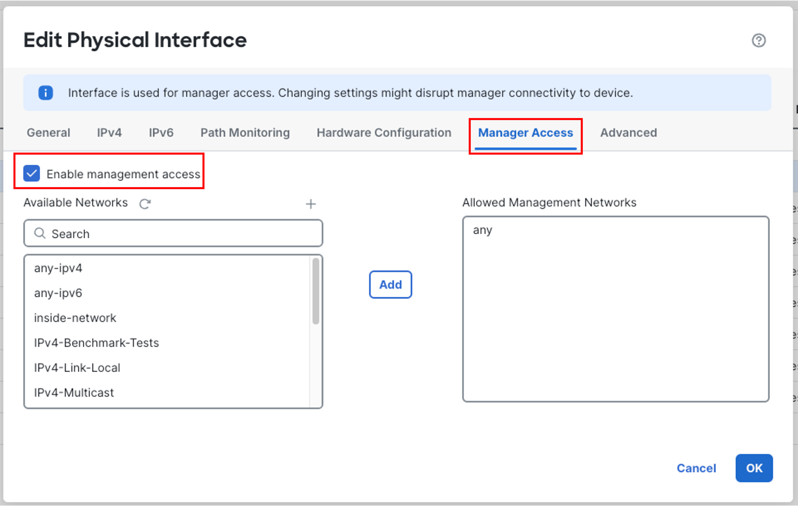
Note:
This configuration option is also visible in the interface listing within Device view page.
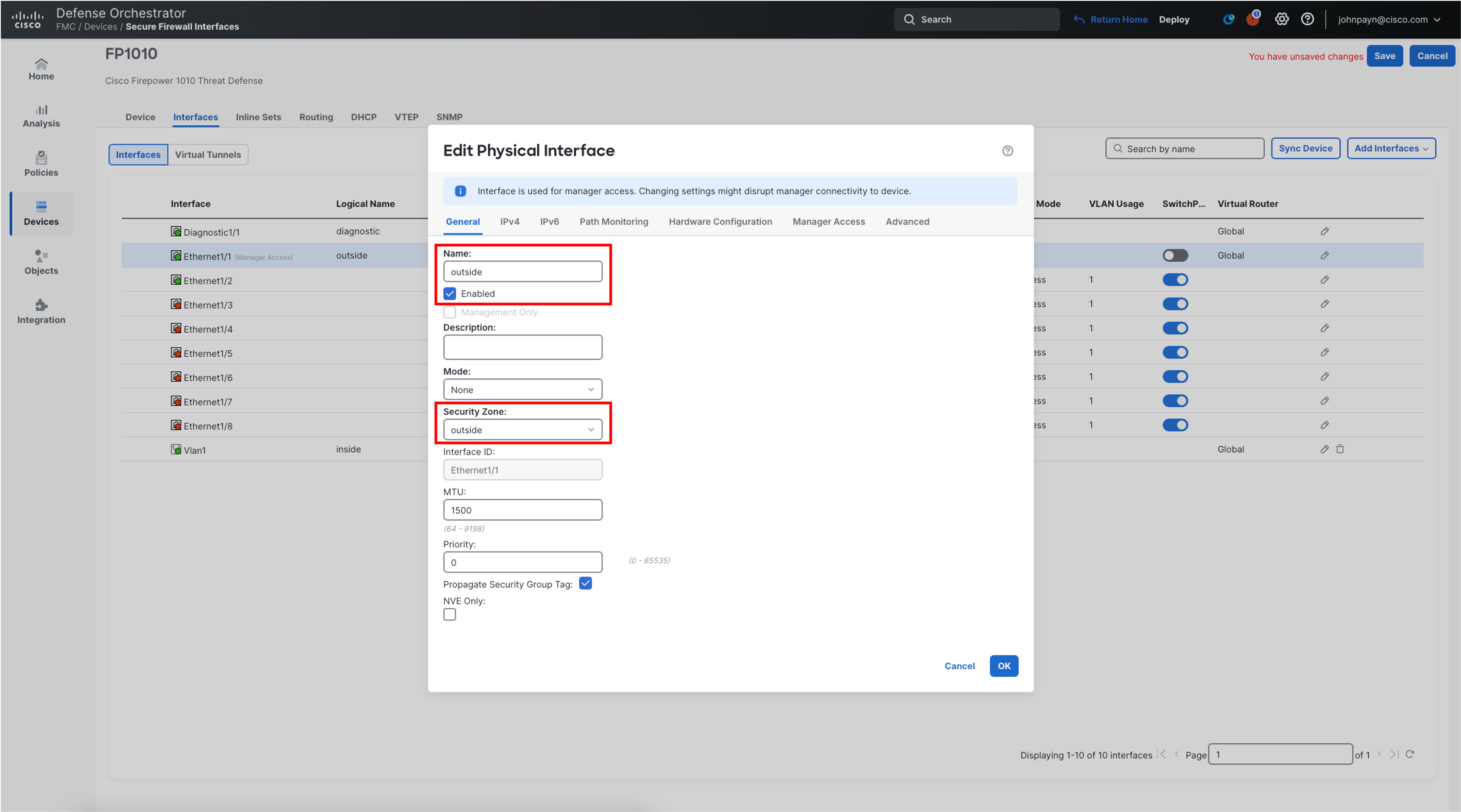
- Click the General tab and ensure the name of the interface is set as outside and the interface status is set to Enabled
- Click the Security Zone: Select New from the drop-down menu and enter outside for the New Security Zone. Click Ok.
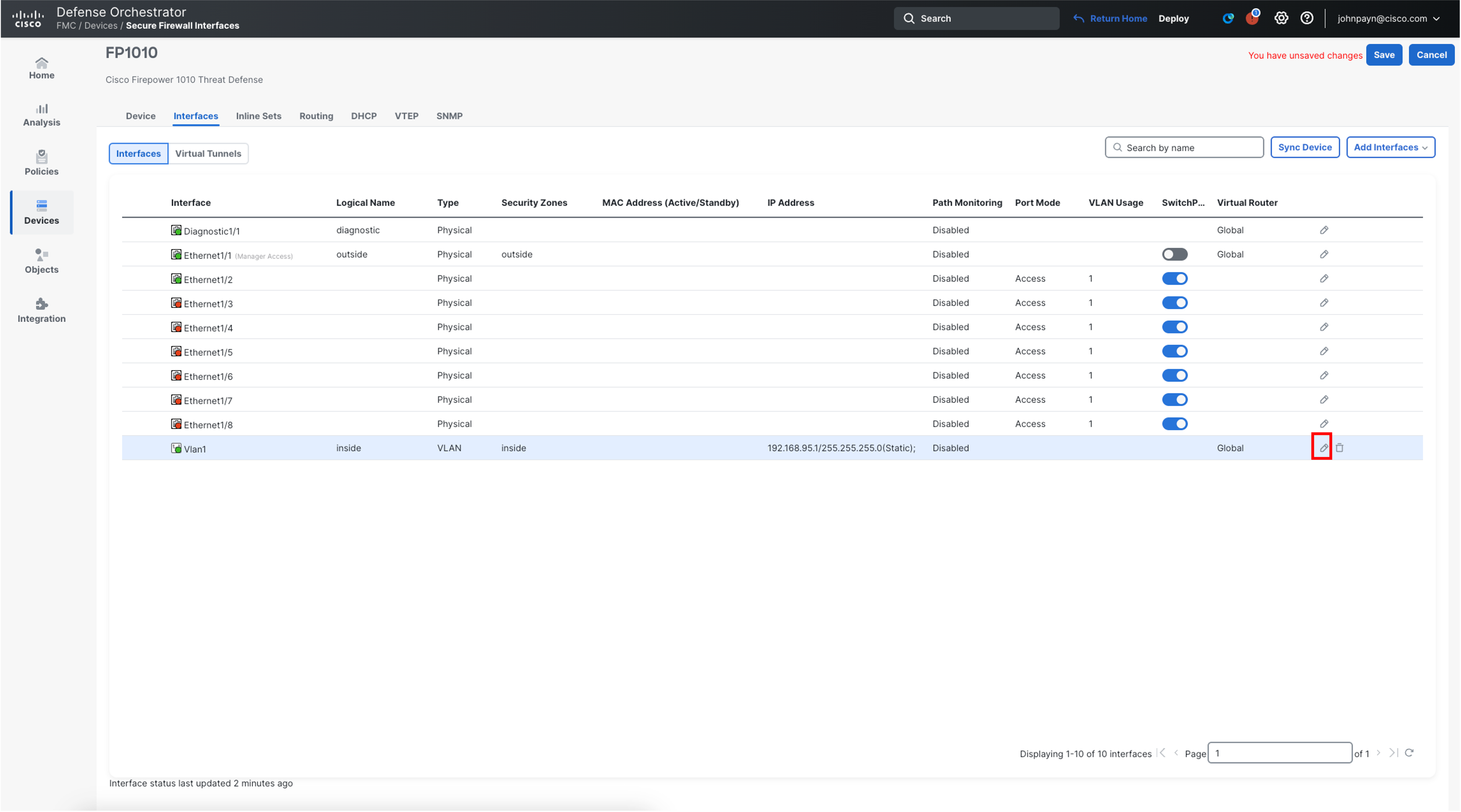
- Edit the VLAN1 interface, by clicking the pencil icon.
- Ensure the Name value is set to inside and that the interface is enabled.
- Ensure the Enabled box is checked.
- For Security Zone, Select New from the drop-down menu and enter inside for the New Security Zone.
- Click Ok in the bottom-right of the Edit VLAN Interface window.
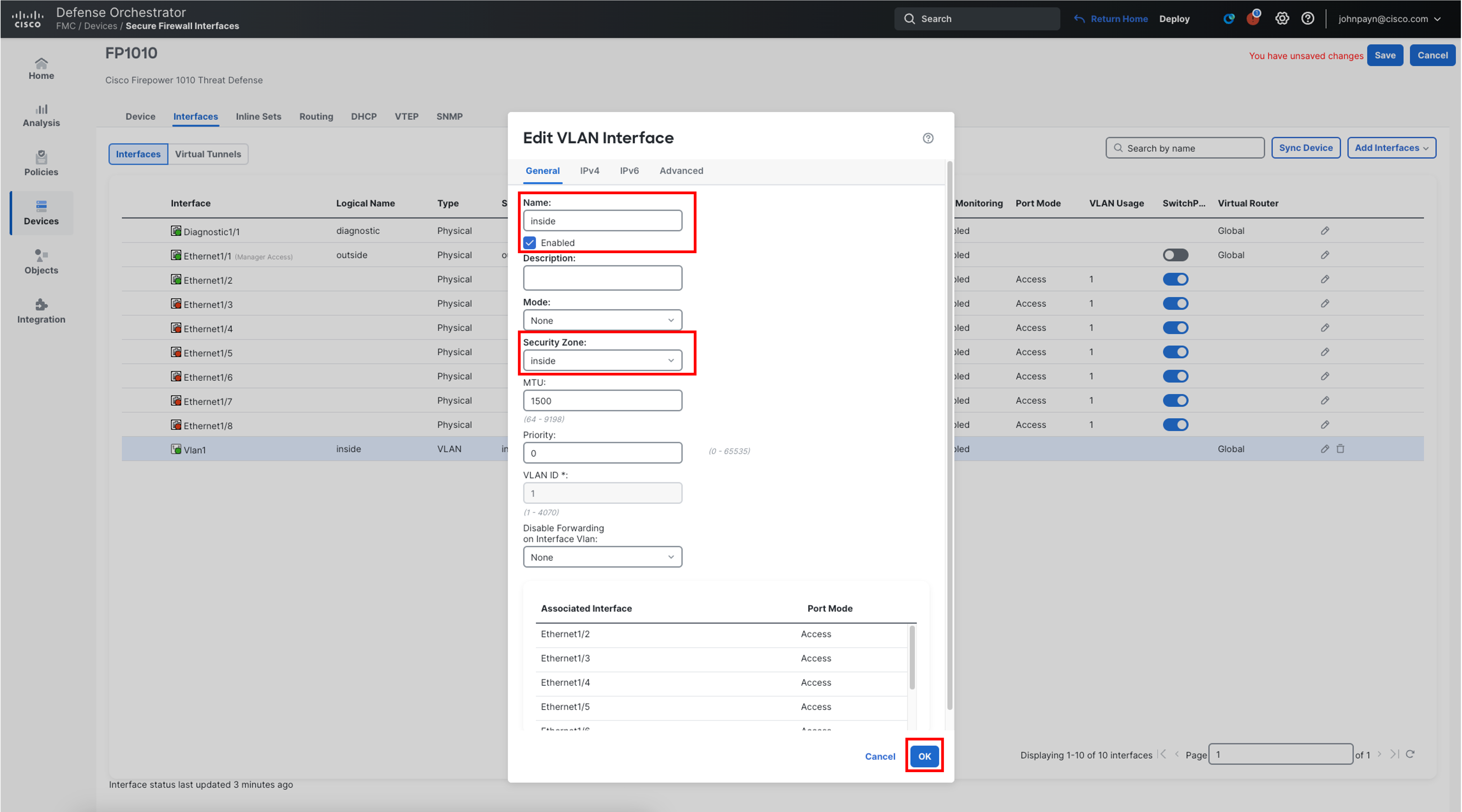
- Click Save on the top right to save the interface configuration.

DHCP Server Configuration
-
To configure the Firewall as a DHCP Server for the devices connected on the inside interface, select DHCP from the same device configuration page and navigate to DHCP section
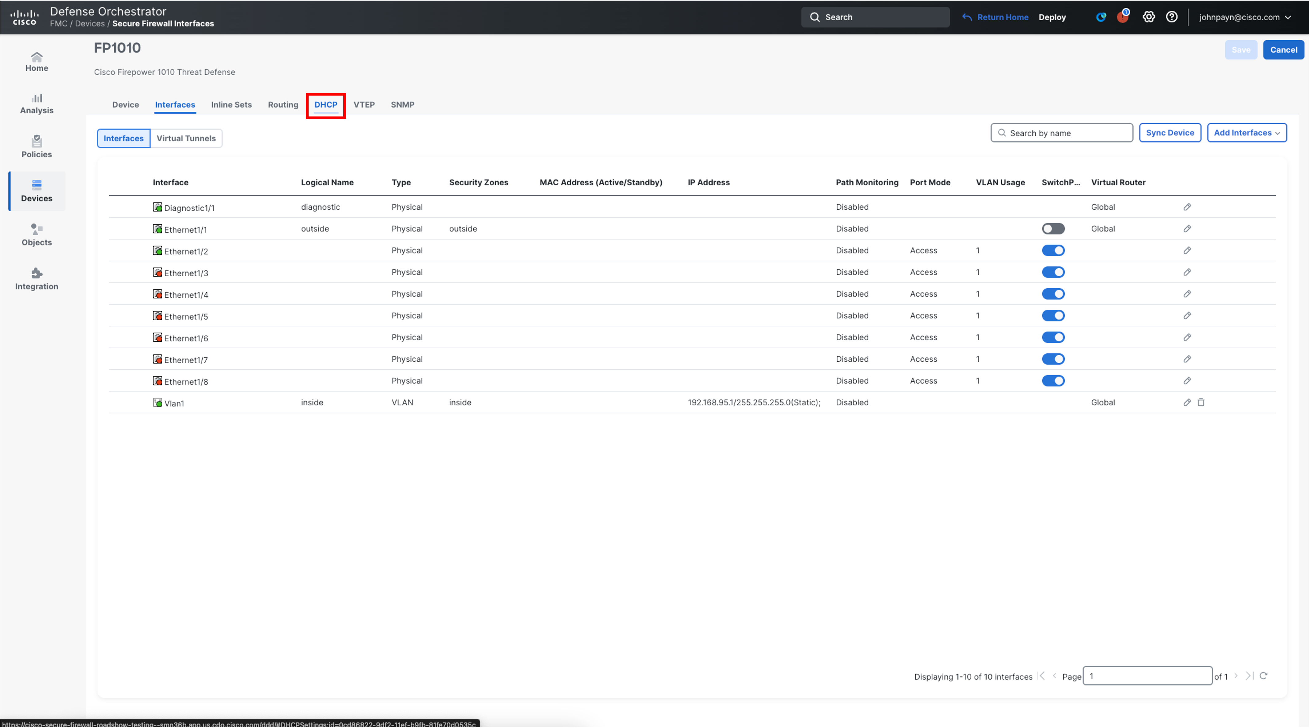
-
Click Add to add a DHCP server
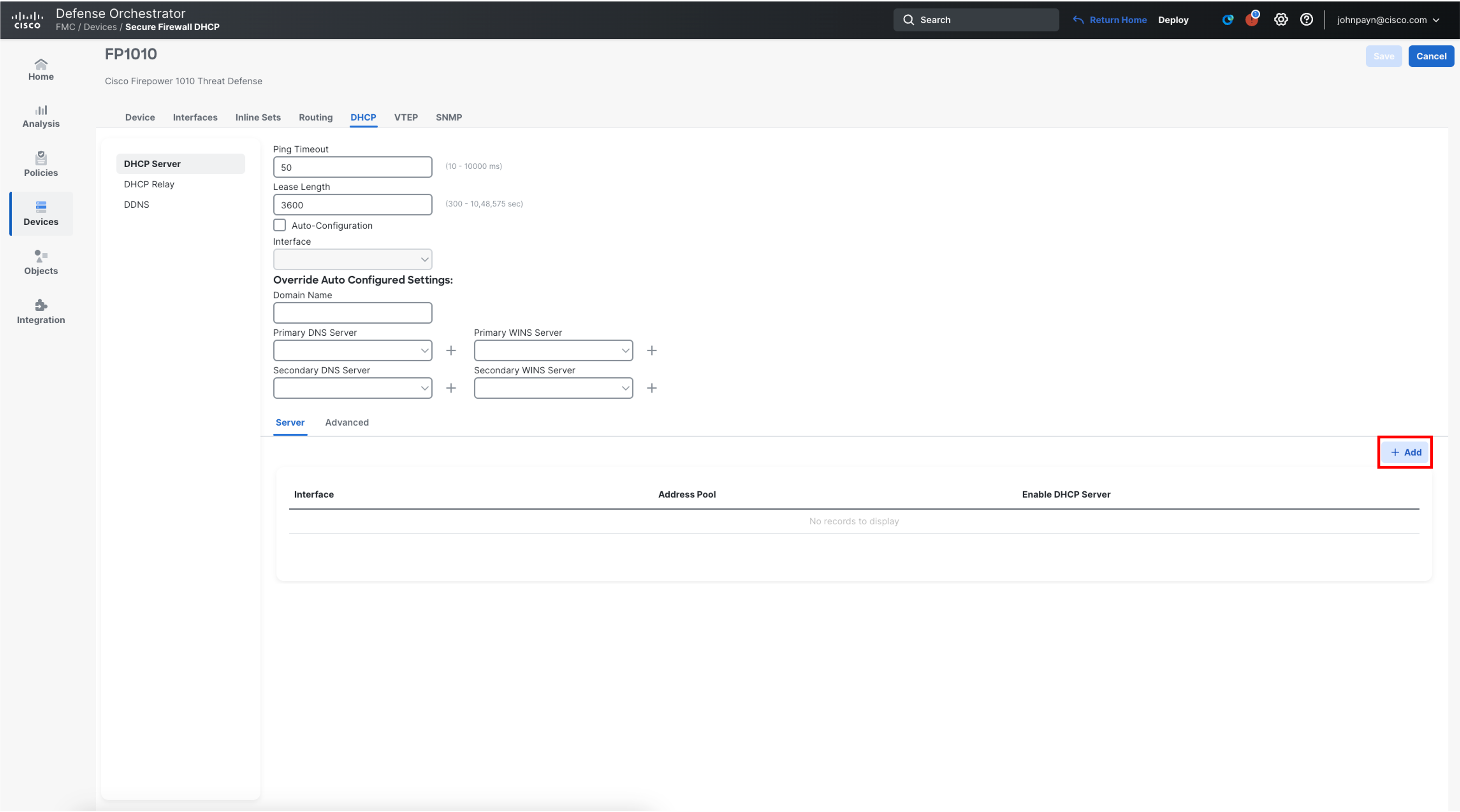
-
Select inside from the Interface drop-down list
-
ForAddress Pool, enter the range of IP addresses which will be used by the DHCP Server 192.168.95.10-192.168.95.100
-
Enable the DHCP Server on the selected interface and click OK
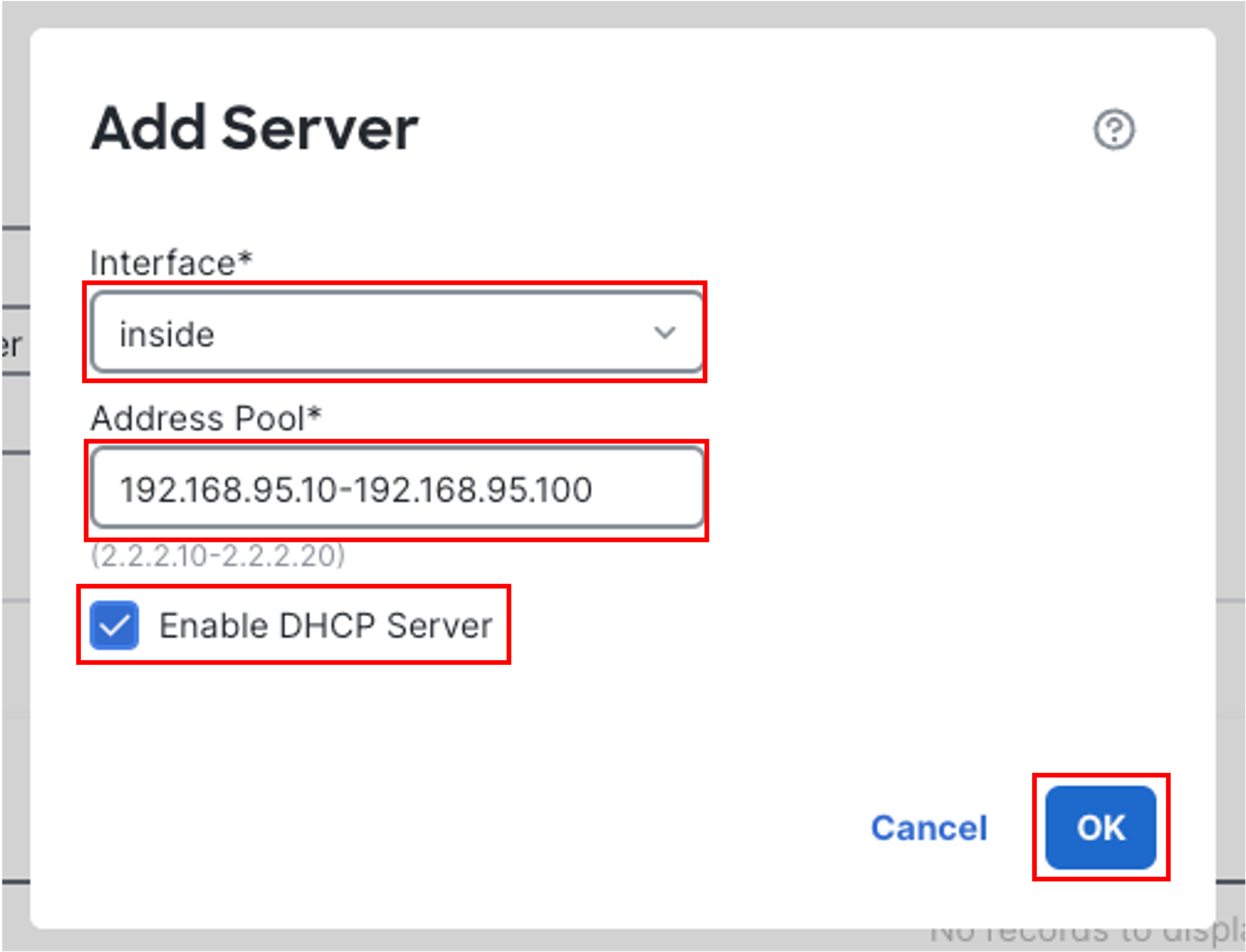
-
Enable Auto-Configuration and select outside from the Interface drop-down list.
Note:
Auto-configuration enables the DHCP server to provide the DHCP clients with the DNS server, domain name, and WINS server information obtained from a DHCP client running on the specified interface , in this case, outside interface.
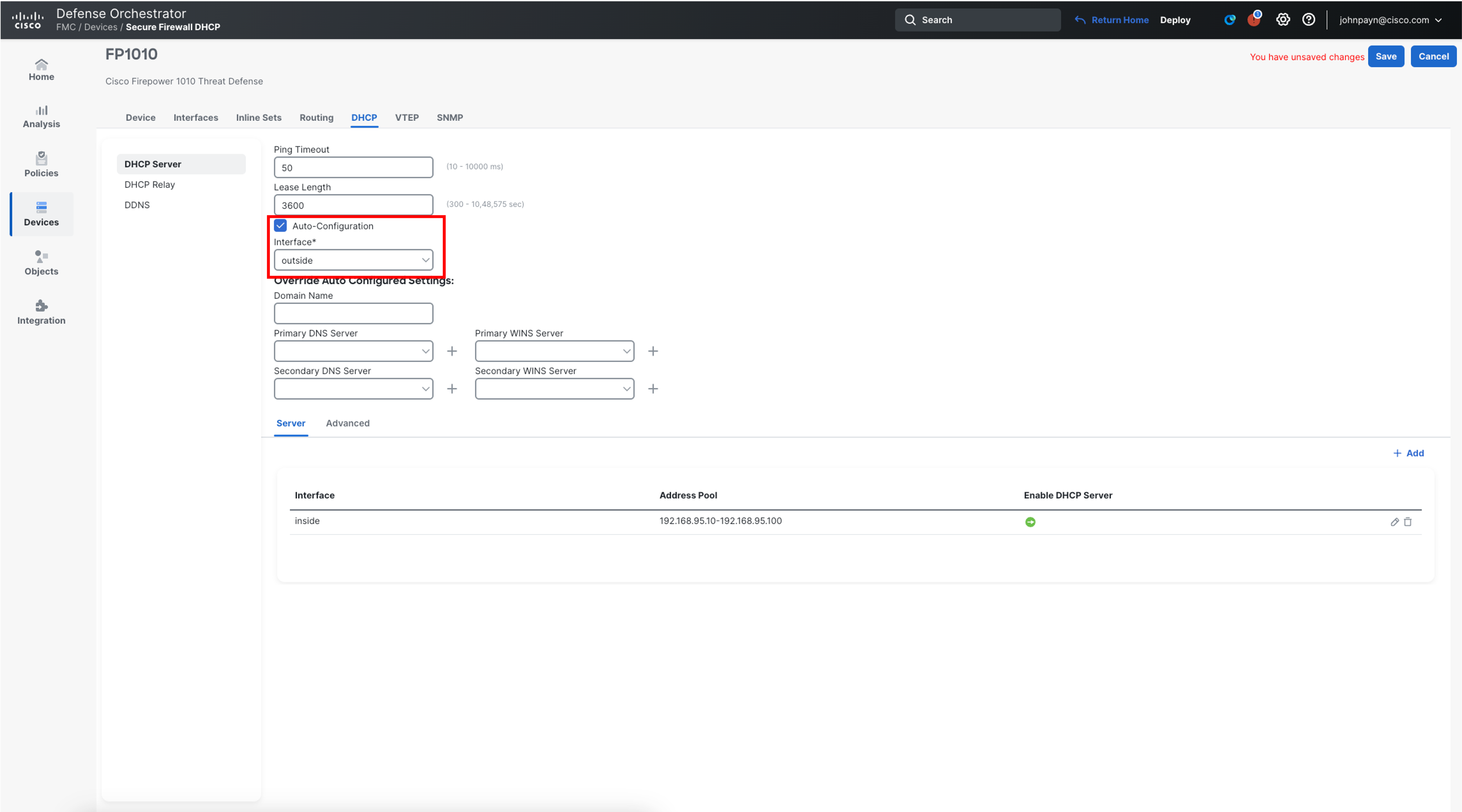
-
Click Save on the top right of the page to save the configuration changes to the FMC.
DNS Server Configuration
-
To configure the dedicated servers to be used by Secure Firewall device for DNS resolution, navigate to Devices > Platform Settings from the left navigation bar.
-
Click New Policy and then select Threat Defense Settings.
-
Enter the Name as FP1010-PlatformSettings.
-
Choose your Firewall from the Available Devices list and add it to the Selected Devices.
-
Click Save.
Warning
You might get a warning while pushing the platform policy to the firewall as there is already DNS configuration present on the device from the initial bootup. Click Ok to proceed.
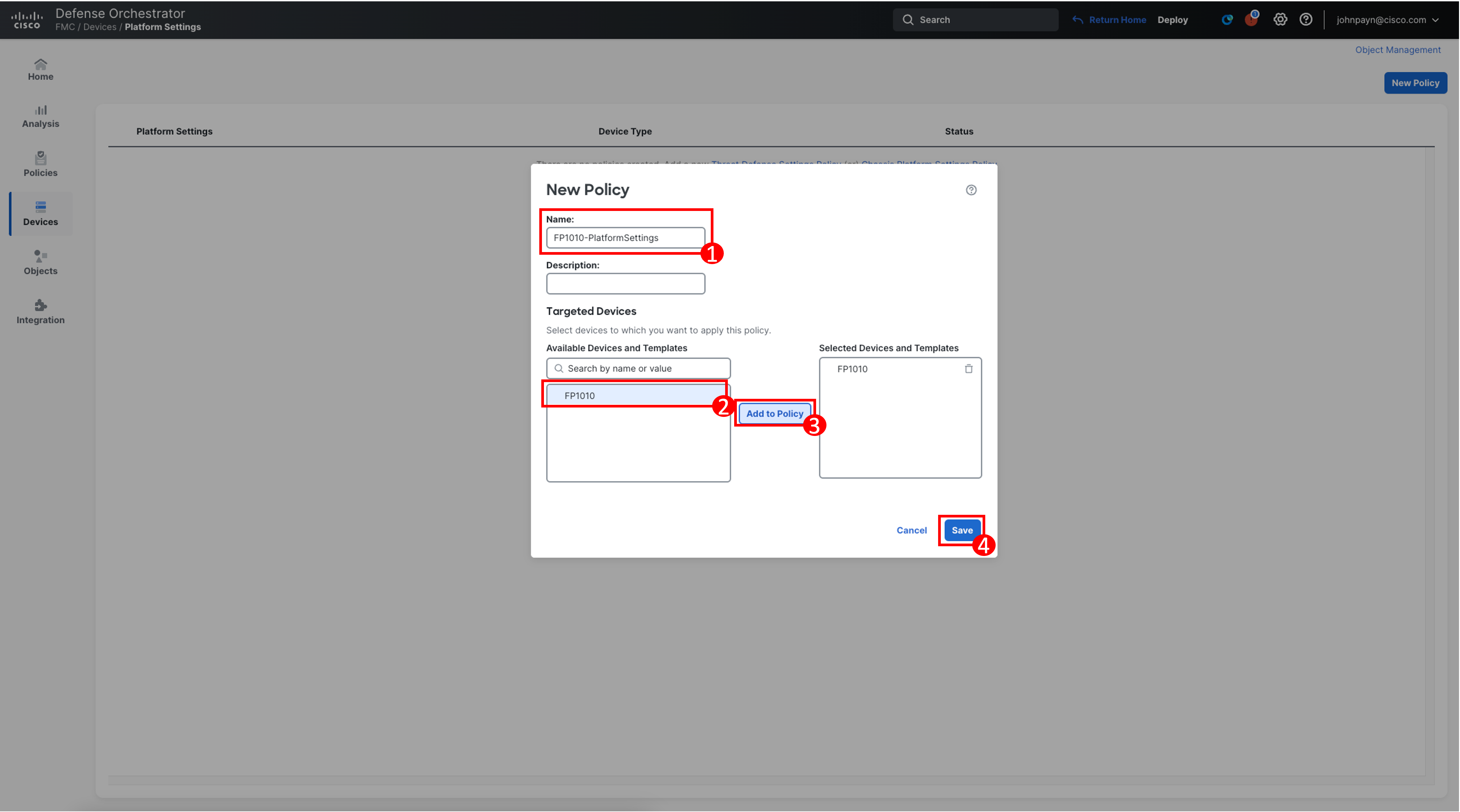
-
To configure DNS server, follow these steps:
-
Click DNS. Toggle Enable DNS name resolution by device
-
Click Add next to the DNS Server Groups.
-
Click New Group in the configuration popup.
-
Enter Umbrella_DNS for name and 208.67.222.222,208.67.220.220 for DNS Servers. Click Save.
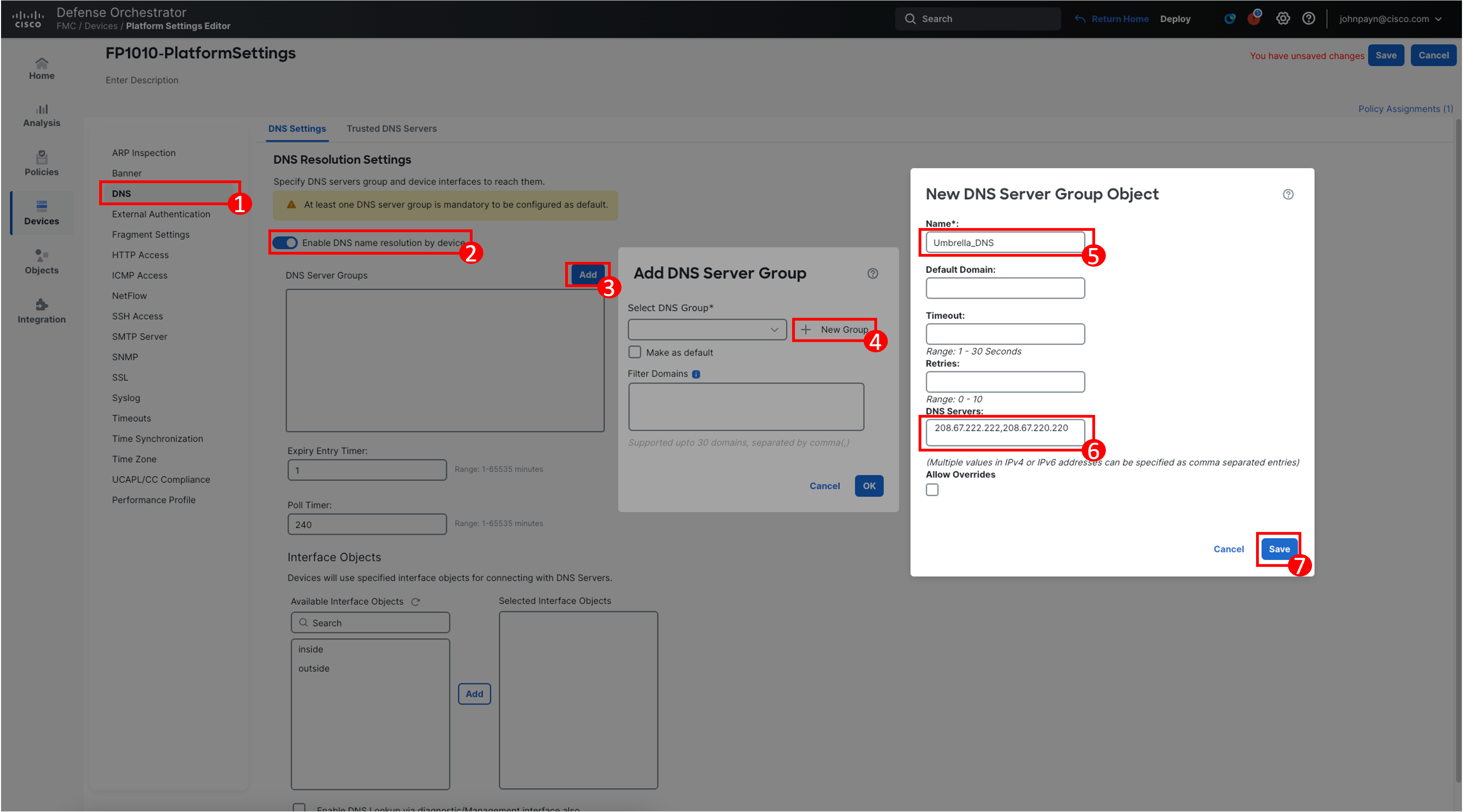
-
Select Umbrella_DNS from the DNS Group drop-down list. Select Make as Default. Click Ok.
-
Click Save on the top right of the page to save the configuration changes to the FMC.
-
NAT Configuration
-
To configure the dynamic NAT configuration to allow the LAN network users to be able to access the internet, click Devices from the main menu ribbon at the top and then select NAT.
-
Click New Policy.
-
Name the policy FP1010NAT, select the FP1010 from the available devices, click Add to Policy and click Save.
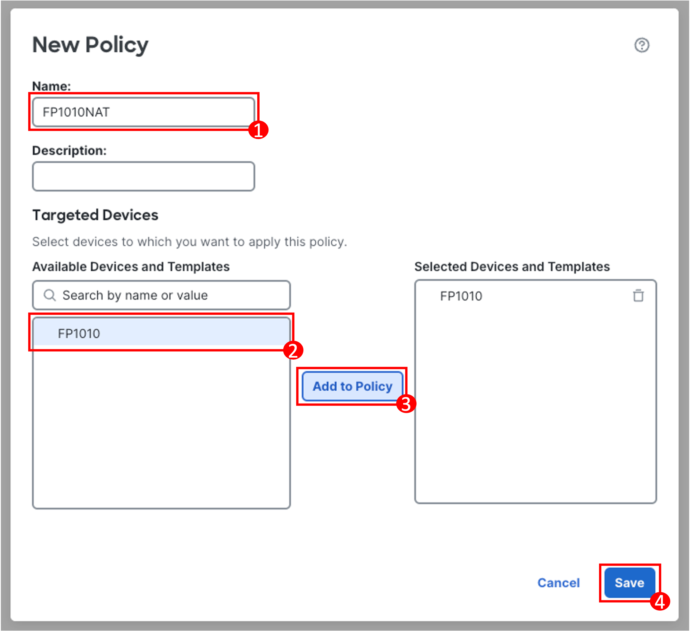
-
To configure the rules to allow Outbound Internet access, click Add Rule in the upper-right.
-
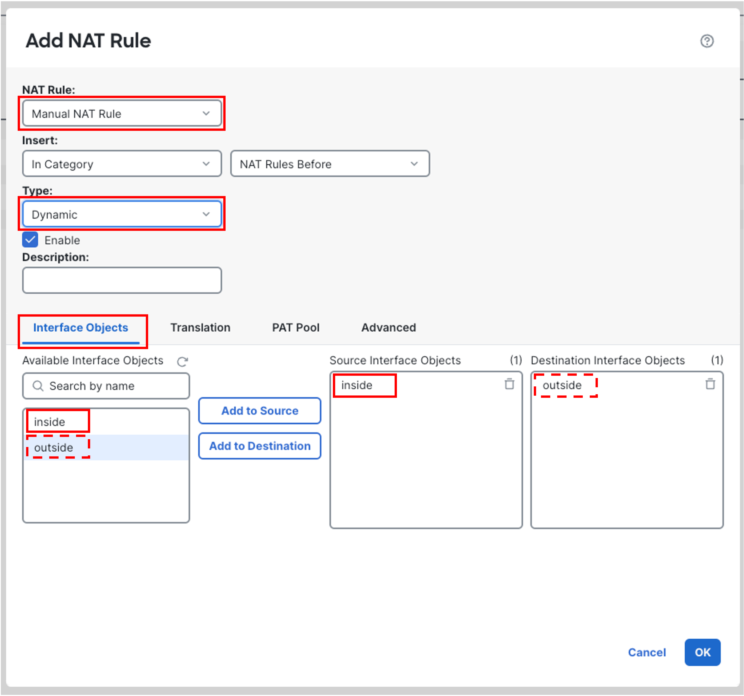
For NAT rule, select Manual NAT Rule
-
For Type, select Dynamic
-
Click Interface Objects
-
Select Inside. Click Add to Source.
-
Select Outside. Click Add to Destination.
-
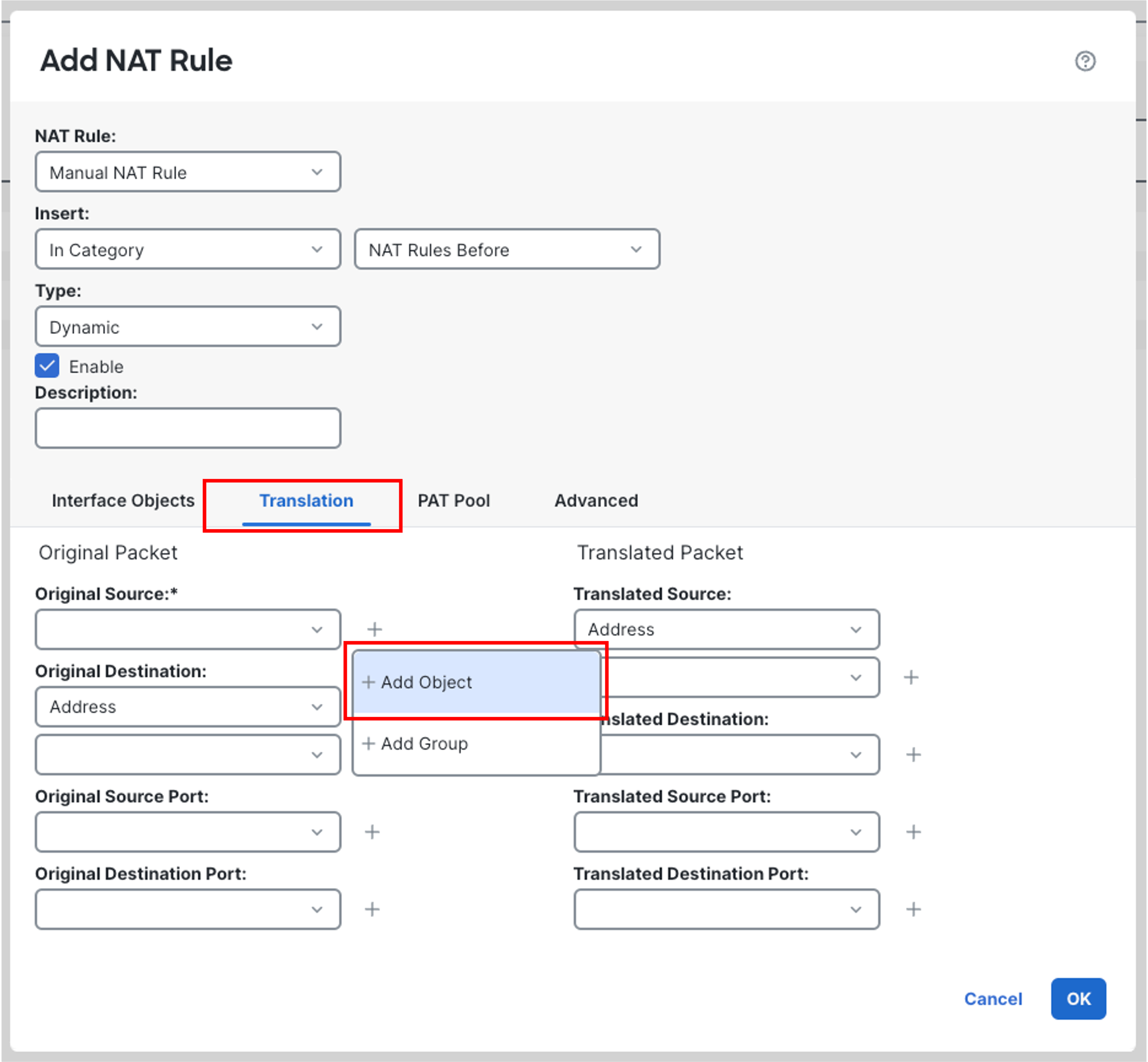
Click Translation
-
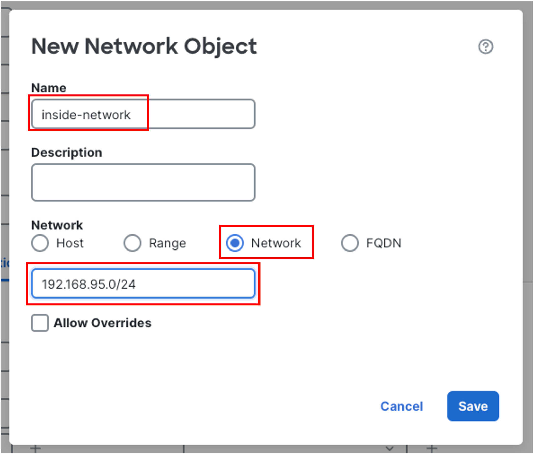
Click the plus icon next to Original Source. Click Add Object and create a Network Object as shown below. Click Save.
-
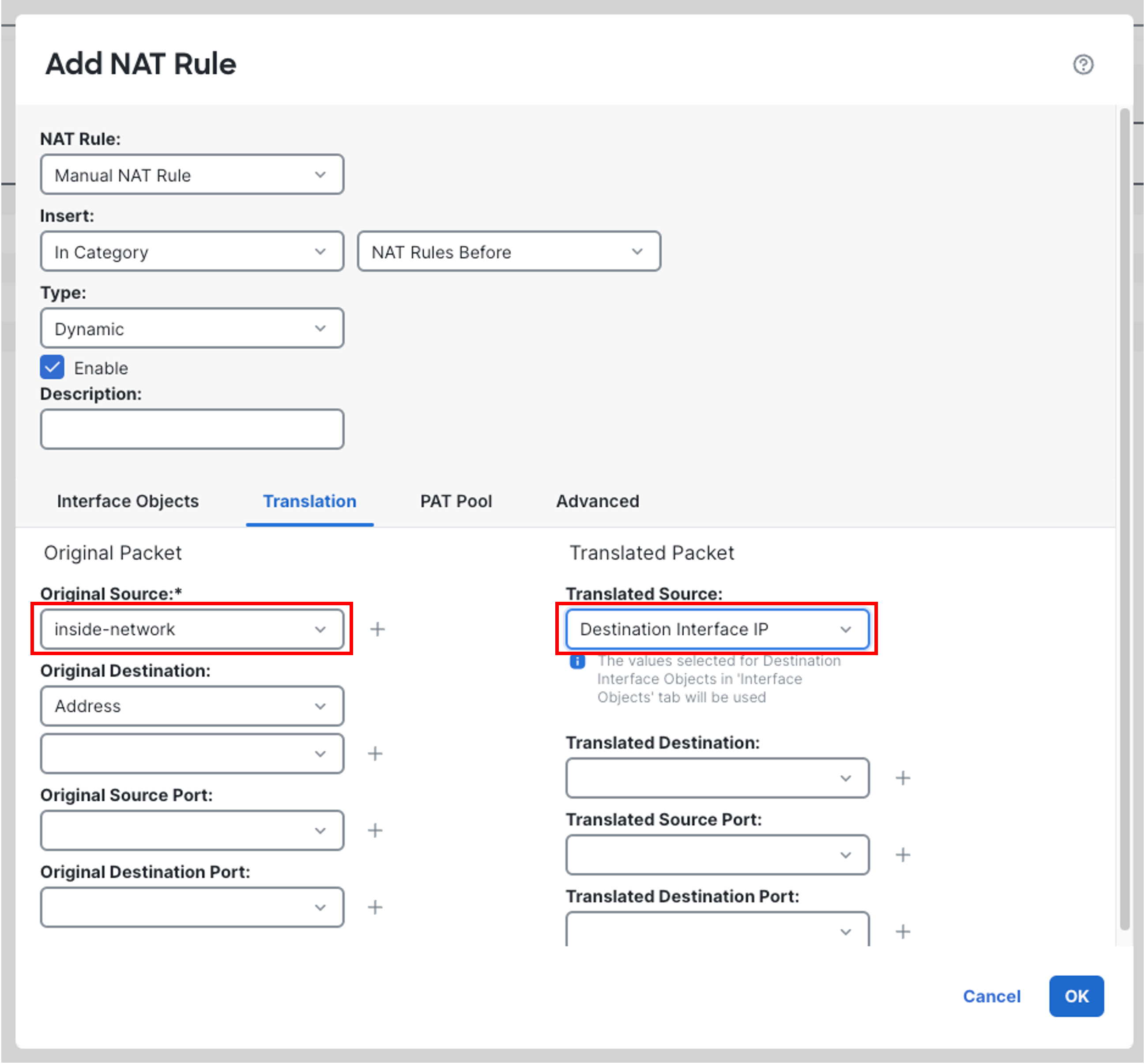
Ensure inside-network is already selected as Original Source , if not, click on drop-down list and select inside-network. Select Destination Interface IP from the Translated Source drop-down list.
-
Click OK and then click Save to save the NAT policy.
-
-
Routing Configuration
By the virtue of DHCP configuration on the upstream device, Firewall 1010's outside interface is assigned a DHCP address well as a default route. For this lab, you will be using that route and not configuring any additional routes.
Access Control Policy (ACP) Configuration
- During onboarding, the device is assigned the Default Access Control Policy to the Firewall. It is a generic policy with the default action of Block All Traffic. Now, we will create a new Access Control Policy to allow Outbound Internet traffic and assign it to the Firewall.
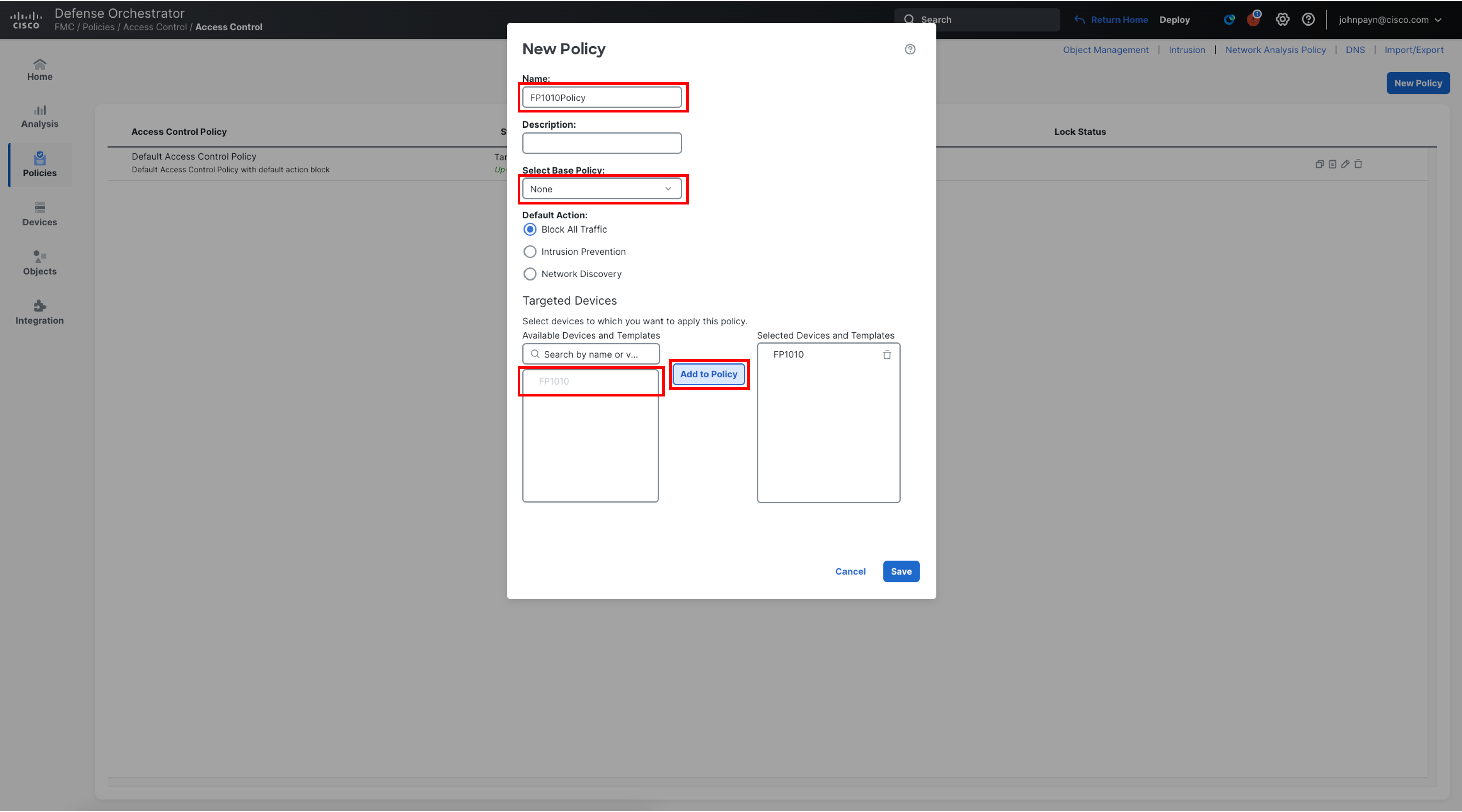
- From the Main Menu on the left, choose Policies > Access Control > Access Control. Then select New Policy and enter the following details.
- Name: FP1010Policy
- Select Base Policy: None. This setting can be used to inherit configuration from a parent Access Control Policy, which can be overridden within the child policy.
- Default Action: Block All Traffic
- Targeted Devices: Select FP1010 from the list of Available Devices. Click Add to Policy. It should be added to the Selected Devices pane.
- Click Save.
Note
You might get a Warning as the Firewall was already assigned the policy Default Access Control Policy at the time of the onboarding. To accept the warning, click Yes and proceed further.
-
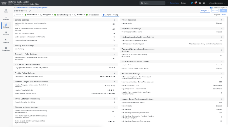
Now, we will configure some additional settings that give us more visibility into Encrypted Traffic, without decrypting it. You can read more about this capability here. Click More > Advanced Settings to where you will see a page similar to the one below:
-
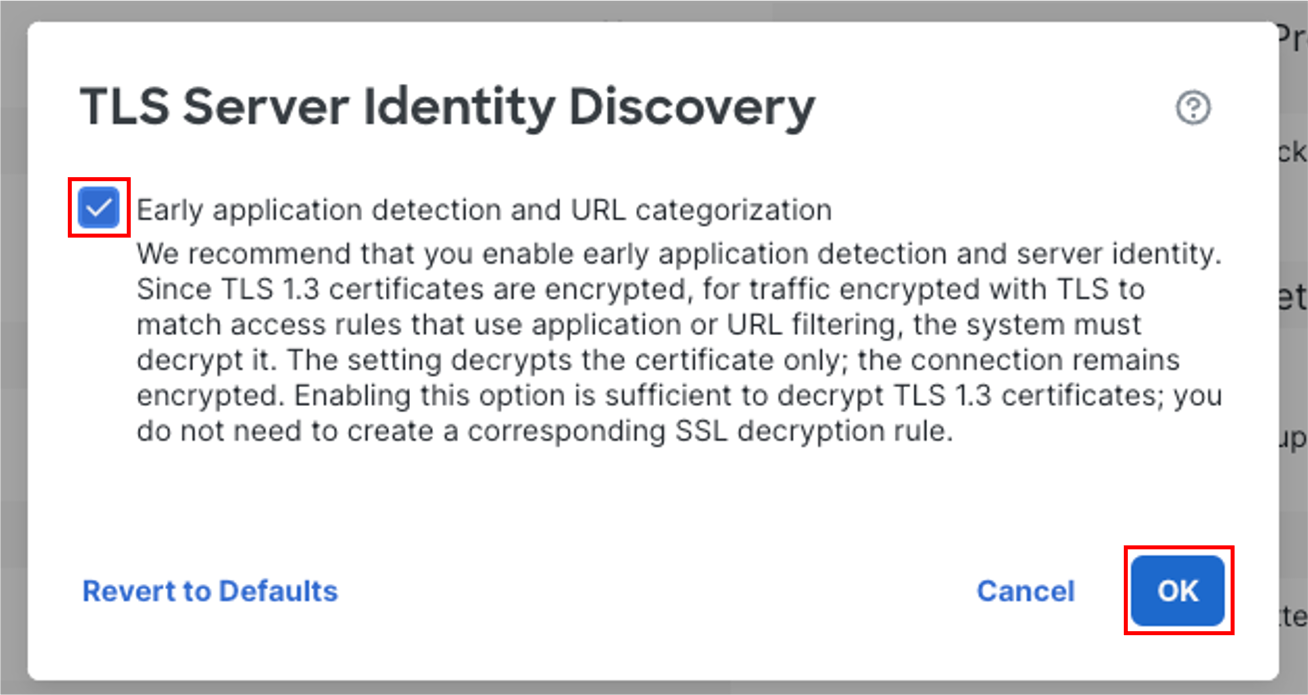
Find TLS Server Identity Discovery and click on the pencil icon. Select the checkbox and click OK.
-
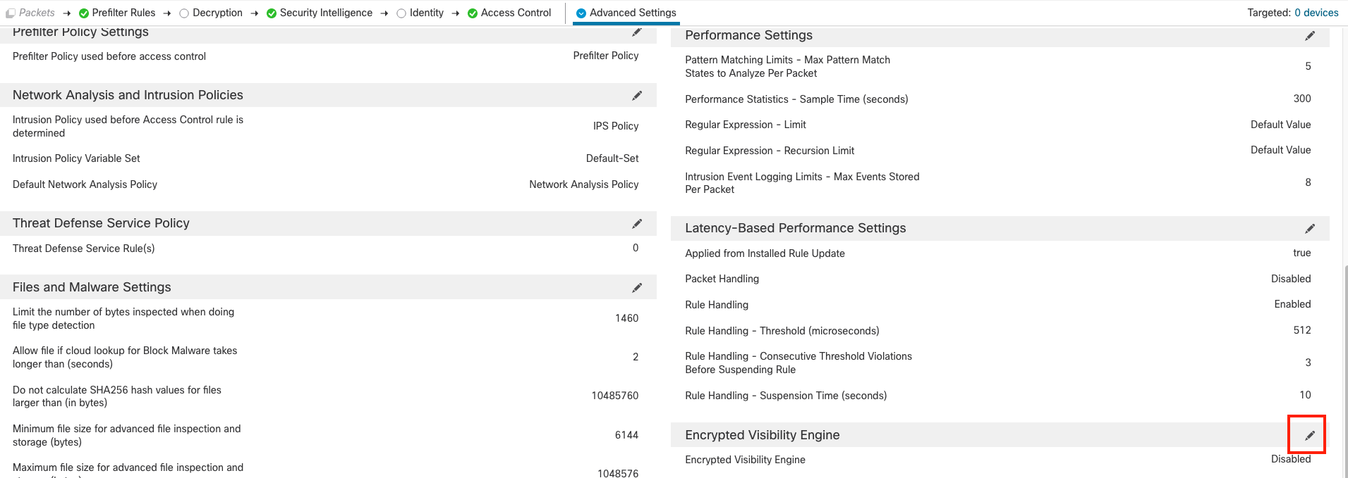
To enable Encrypted Visibility Engine, first scroll-down and click the pencil icon, toggle the slider for Encrypted Visibility Engine and click OK. The features are explained in the configuration popup. You can take some time to read about it.
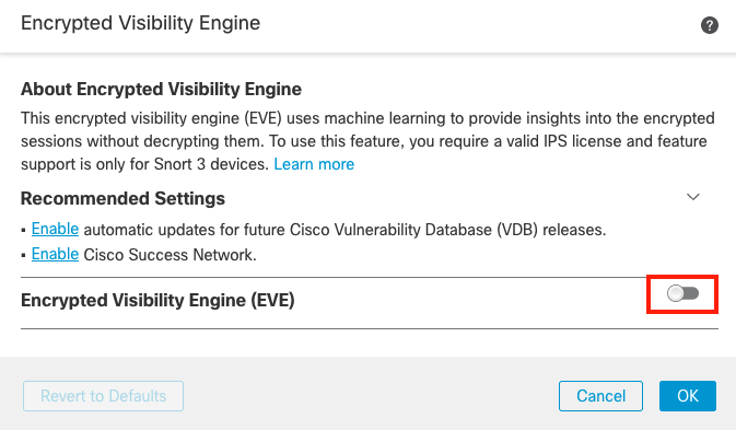
Note
Do not toggle the slider to enable Block Traffic Based on EVE Score.
-
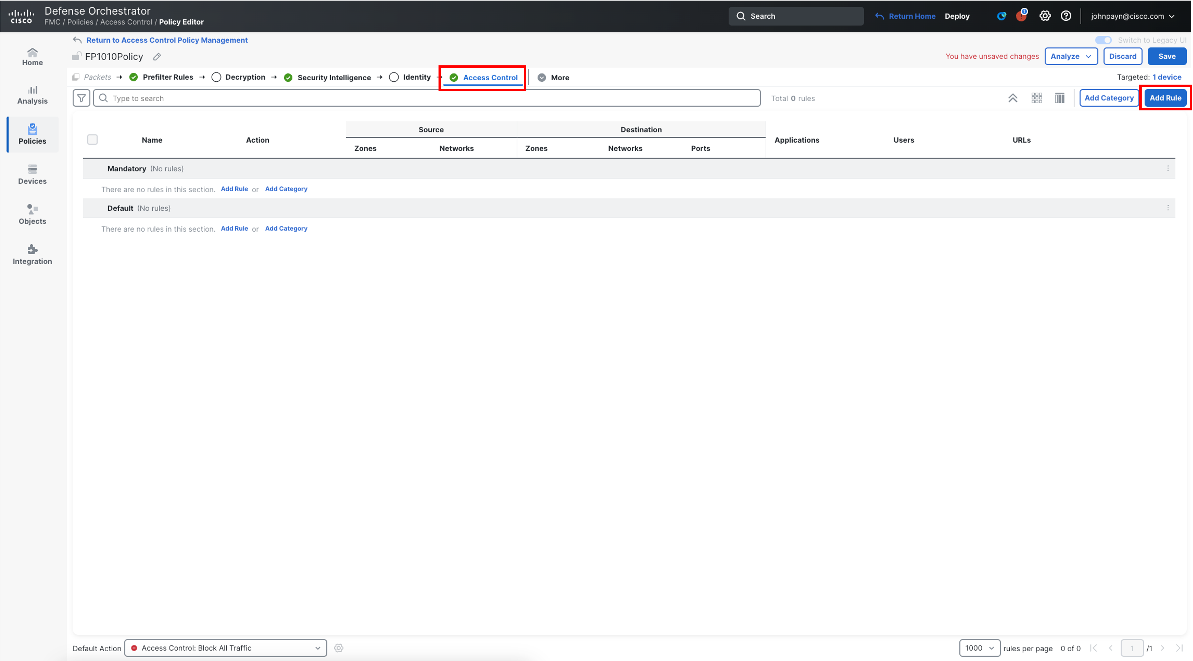
Click Access Control towards the top in the policy selector. Click Add Rule, and configure the following rule.
-
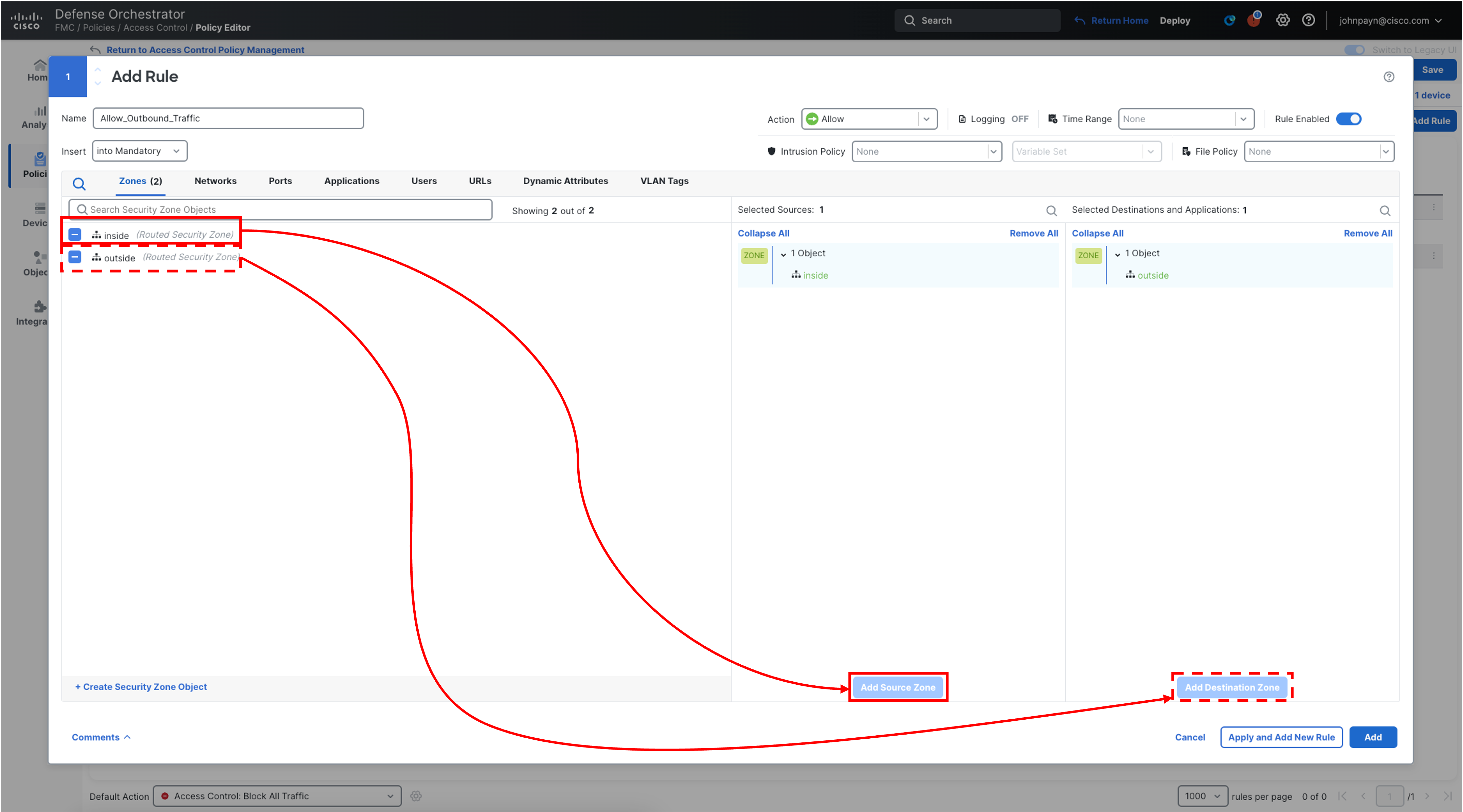
Name: Allow_Outbound_Traffic
-
Select inside from Zones and click Add Source Zone
-
Select outside , and click Add Destination Zone
-
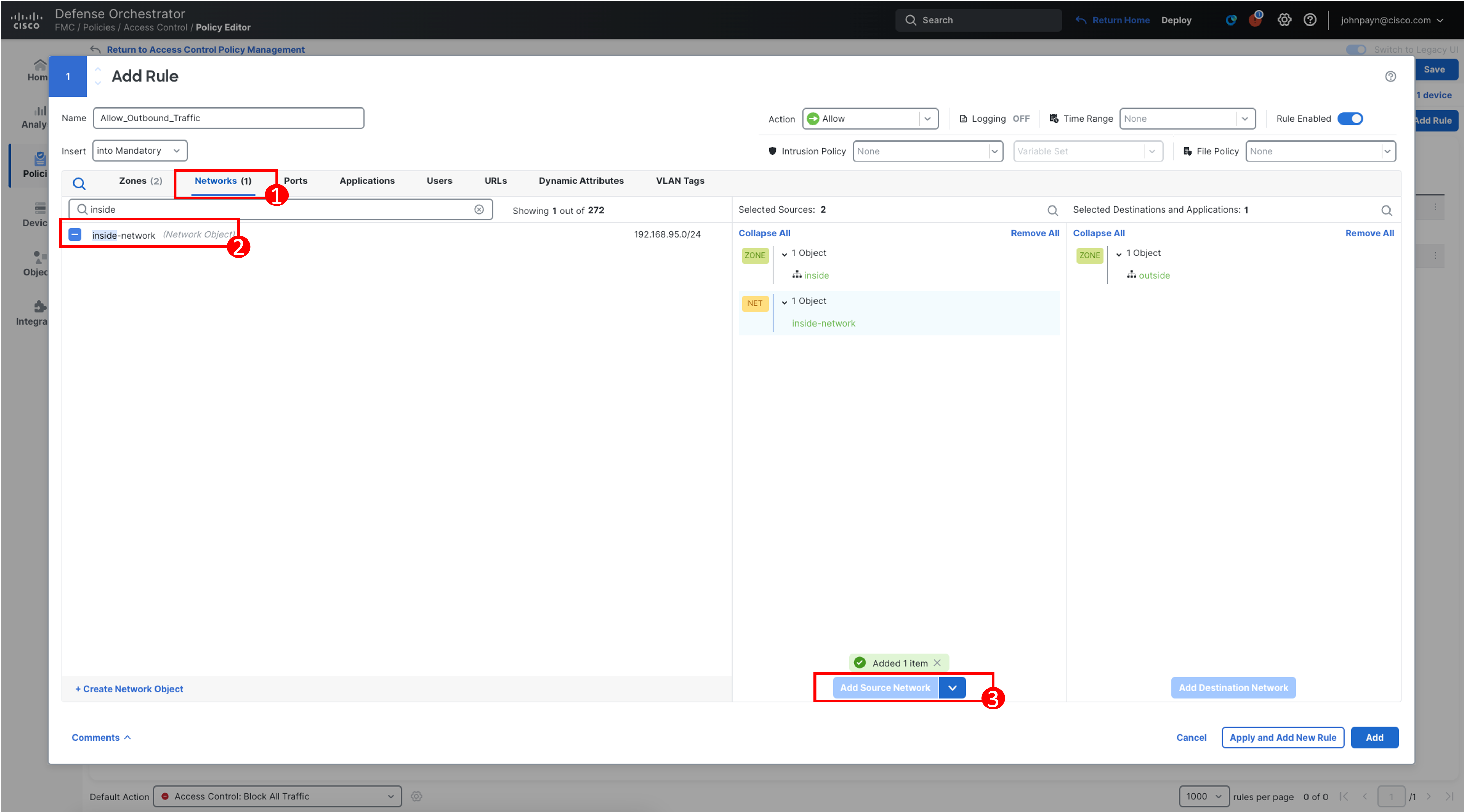
Click Networks, and search for inside-network. Select and click Add Source Network
-
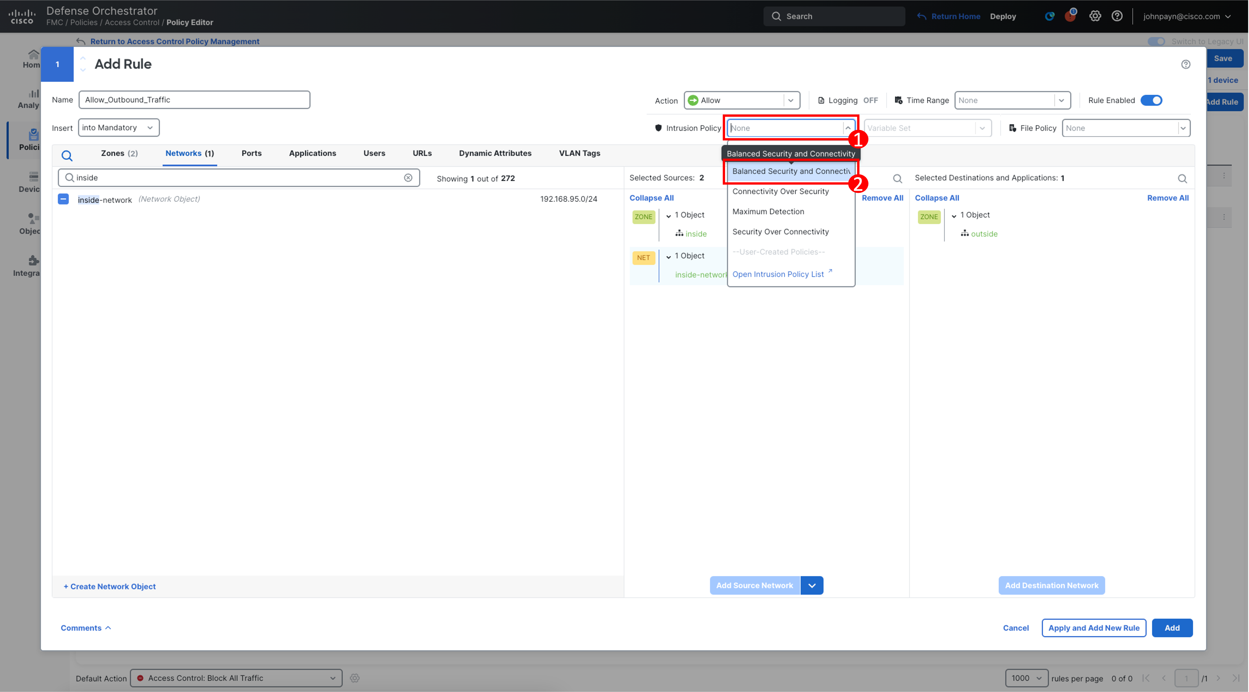
In the Intrusion Policy drop-down list, select Balanced Security and Connectivity. There are additional IPS tuning mechanisms available which are not being covered in this lab section.
-
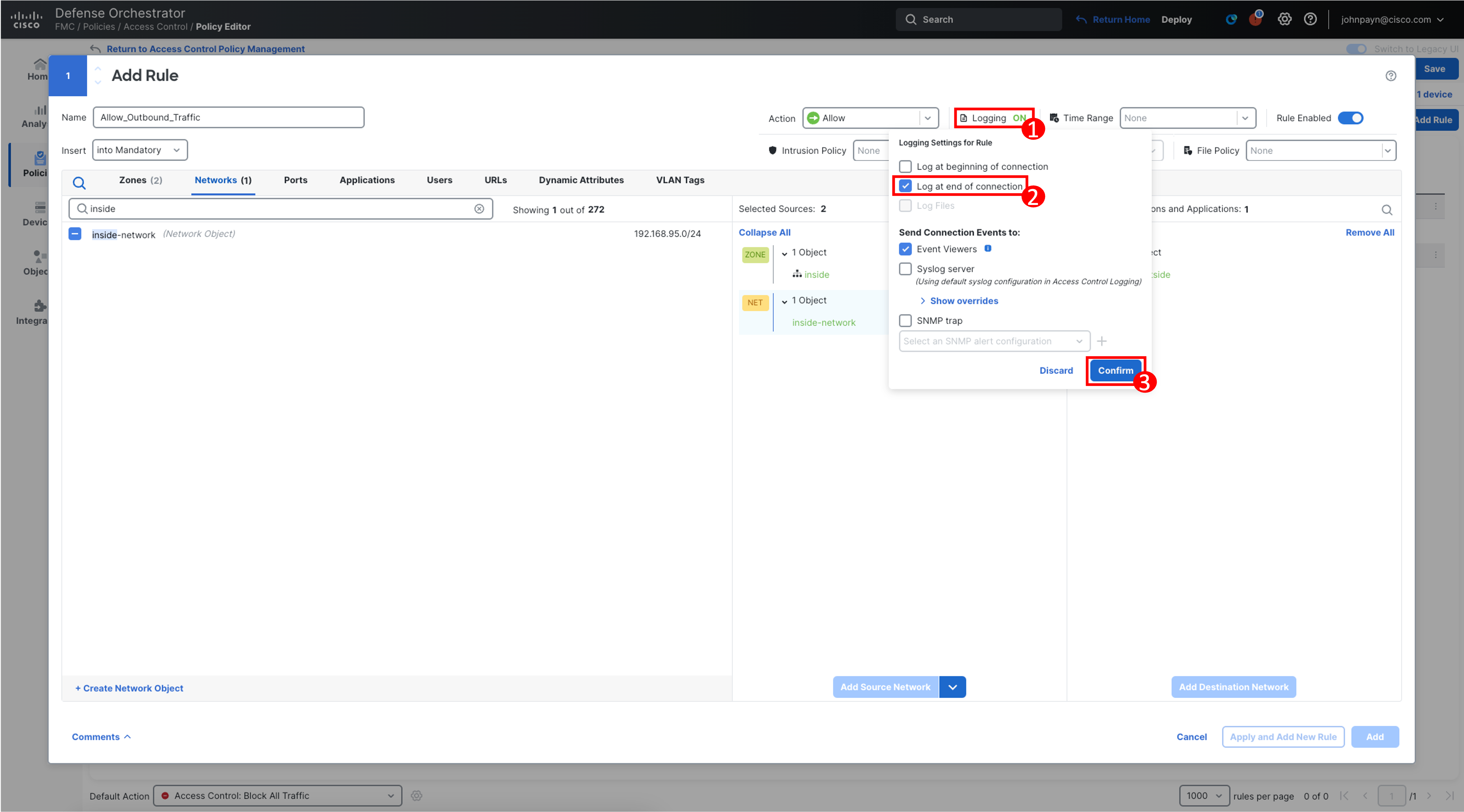
Select Logging" and in the popup select Log at end of connection. The destination for the Connection Events is automatically selected as Event Viewers. Click Confirm.
Note
There are more capable logging settings available. However, for this lab, we are just enabling the Connection Events to be sent to the Security Cloud Control Event Viewer. Also, as part of best practices, we enabled logging only at the end of a connection.
-
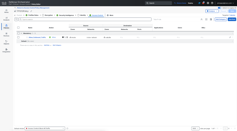
Click Add, and then click Save at the top, to save all the changes to the Access Control Policy configuration. Your Access Control Policy should match the configuration in the screnshot below:
Additional Steps for POV/Customer Demo
To ensure additional configuration options within Access Control Policy, it is highly recommended that you follow the steps in the Task2 of the Threat (Attack IQ) - Training Outline guide before you plan to present the demo to customers or leverage the firewall to secure your network.
A sample access control policy highlighting most of the capabilities of Secure Firewall Threat Defense looks as follows:
Note
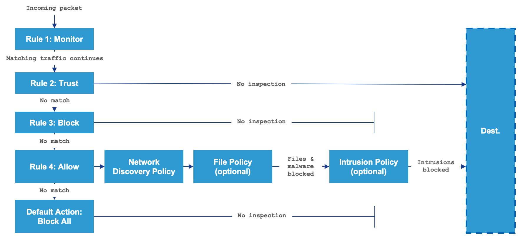
Access Control Policy is a set or collection of rules that define how devices on a network communicate. This feature empowers Secure Firewall Threat Defense to not only provide traditional firewall features like traffic control based on Layer 3 and 4 but also enhance security using advanced options, unlike other Cisco solutions, like security intelligence, file and malware detection, deep packet inspection, decryption , URL filtering, network discovery and snort IPS engine powered by TALOS, one of the world's largest security research organization.
All of these configuration options are tied together within the Access Control Policy and the new user interface alleviates configuration complexity and helps administrators to configure rules efficiently. To learn more about the Access Control rule processing and the effective security mechanisms it employs, please refer to the following diagram and/or Access Control Policy link.
Deploying the configuration
-
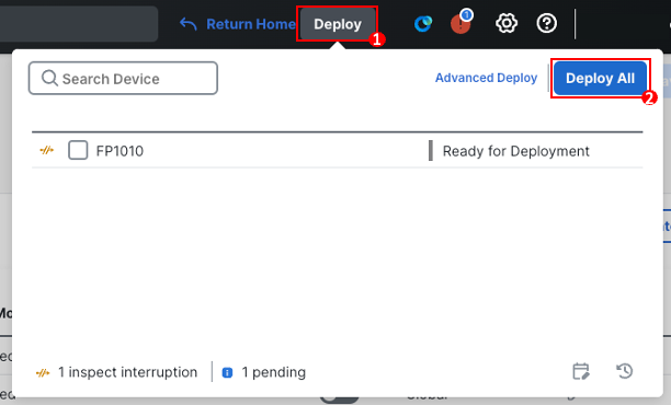
To confirm all the configuration changes are pushed successfully to the firewall, click Deploy in the upper right.
-
Select the device you wish to Deploy to and then click Deploy within the deploy popover menu.
-
Ensure that the deployment succeeds. Click the icon to the right of the Deploy button in the menu bar to see the status for deployments. Ignore any warnings if there are any that prevent the deployment.
-
Once the deployment has been completed successfully, click Return Home in the top menu bar.
-
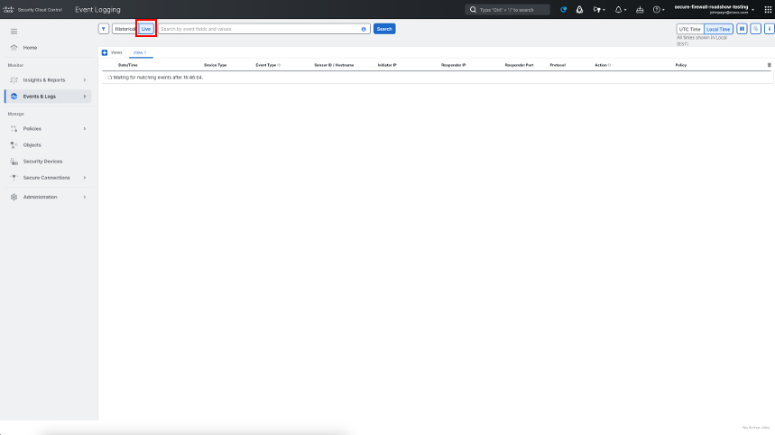
Navigate to Events & Logs Events. This will take you to the Unified Event Viewer available in Security Cloud Control for viewing events sent to the cloud. Select Live at the top to toggle to real-time mode.
-
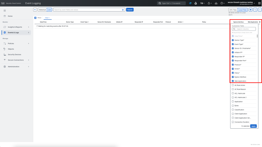
Click on the column selector on the right to include Egress Interface and Web Applicationas columns in the Event Viewer.
Verification
Please read carefully
Firewall 1010 inside interface (Ethernet1/2) is configured as DHCP server so once you connect your own workstation to this interface, you should get an IP address within the range of 192.168.95.10 - 192.168.95.100.
Ensure that your wireless network doesn't overlap or interfere with which is used by Firewall 1010 to assign IP to local LAN users on the inside interface.
-
Ensure the following:
- Your workstation/laptop is connected to the inside interface (i.e. E1/2) of FPR1010
- You are able to ping Ethernet1/2 interface IP of 192.168.95.1.
- You are able to resolve domain names successfully
-
On your workstation, launch the internet browser and navigate to google.com or cisco.com and confirm the websites are accessible.
-
You should see the Events streaming in, as the websites open up. Click Pause and expand a single event to view the details associated with that event such as Firewall name, Policy name, Rule name, Network details etc.
CAUTION
Before proceeding further. ensure that the Firewall 1010 is shutdown gracefully to avoid any issues with configuration and/or database corruption. Please follow the steps below to shutdown the firewall gracefully.
Shutdown Firewall Gracefully
-
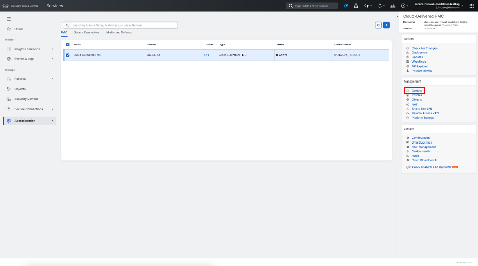
Navigate to Administration > Firewall Management Center
-
Click Devices
-
Choose Devices > Device Management and next to your Firewall 1010, click Edit (pencil icon)
-
Click Device tab

-
To shut down the device, click Shut Down Device (cross icon) in the System section.

-
When prompted, confirm that you want to shut down the device by clicking Yes.
NOTE
Wait approximately 3 minutes to ensure the system has shut down successfully.
License migration
This section lists down the steps needed to move your cdFMC tenant from the roadshow's Smart licensing account to your own Smart account for licensing purposes.
-
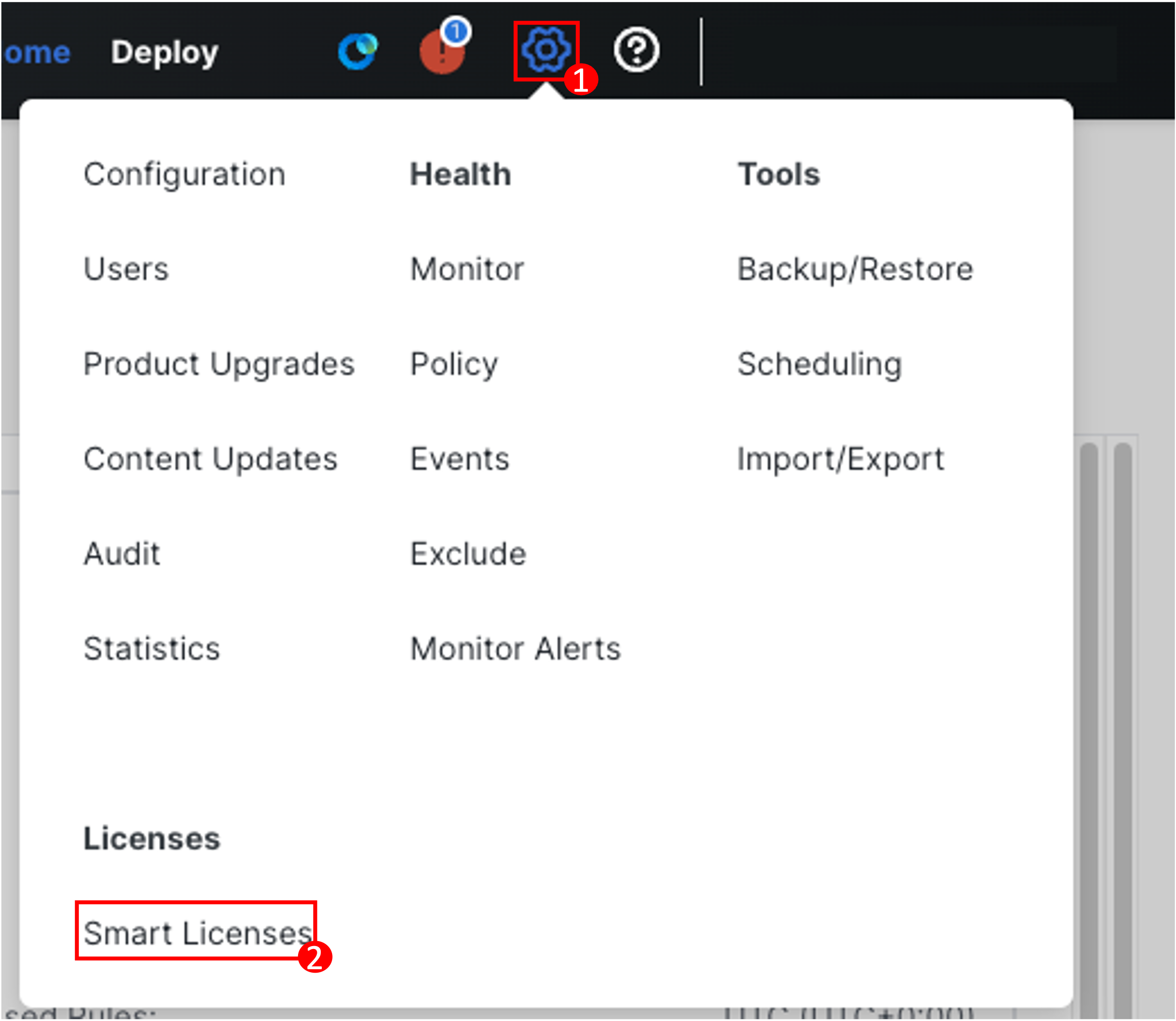
Navigate to System (gear icon) > Licenses > Smart Licenses
-
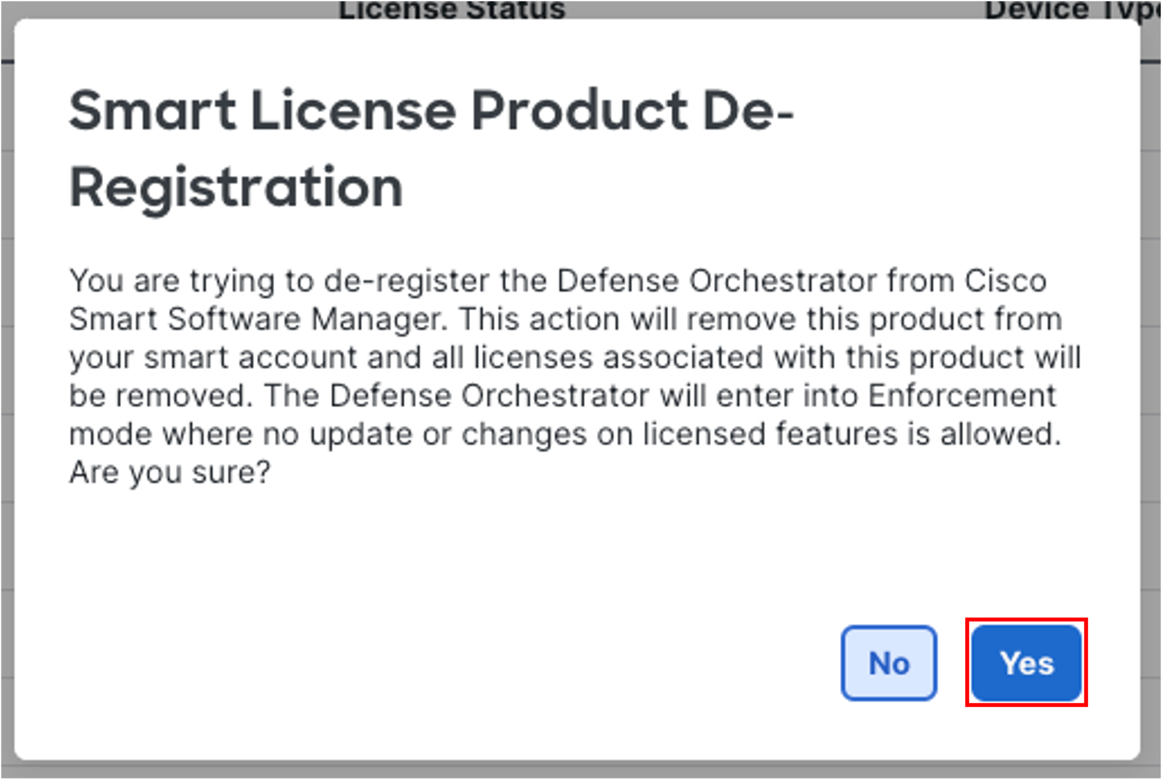
Click Deregister

-
Click Yes to confirm the de-registration
-
Once de-registration is successful, navigate to your https://software.cisco.com and log in into your Smart account to generate a token.
Note
Ensure you generate a token from your own virtual account and have the correct licenses added in your smart licensing account before you start this license migration. Follow this document to know how to generate token: https://www.cisco.com/c/en/us/support/docs/licensing/common-licensing-issues/how-to/device-management/lic220943-how-can-i-create-a-token-to-register-my.html
-
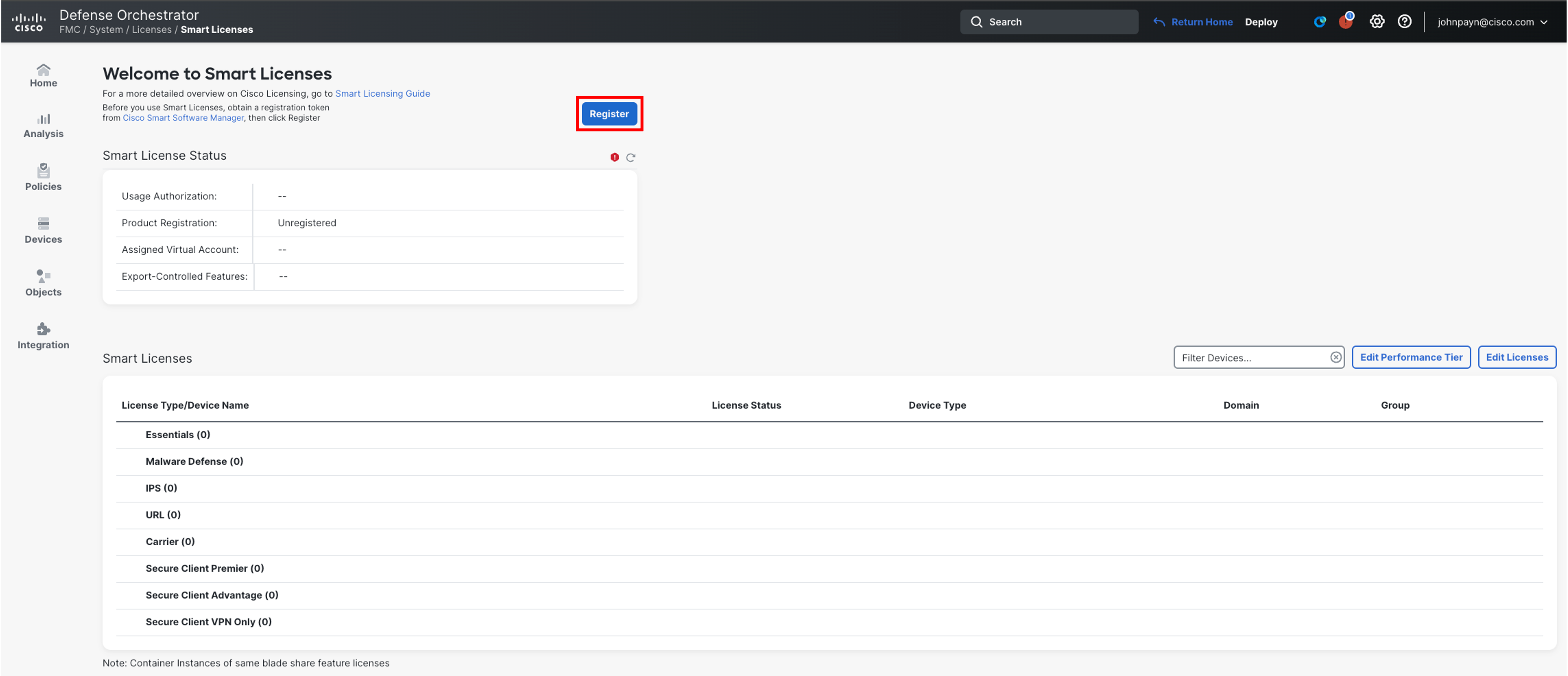
Back on the cdFMC Smart Licenses page, click Register.
-
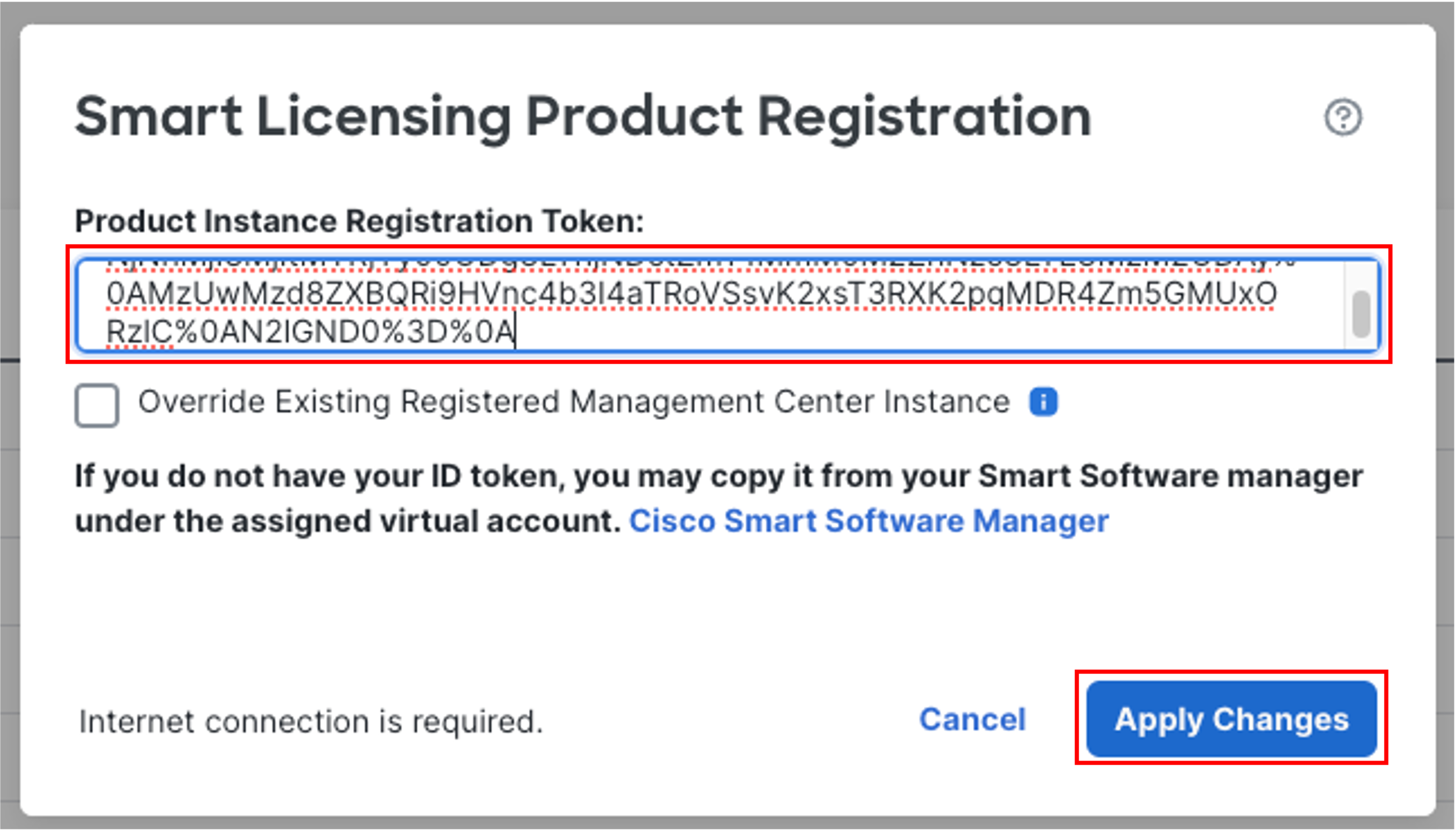
Add the token generated in Step 4 in the Product Instance Registration Token box and click Apply Changes.
-
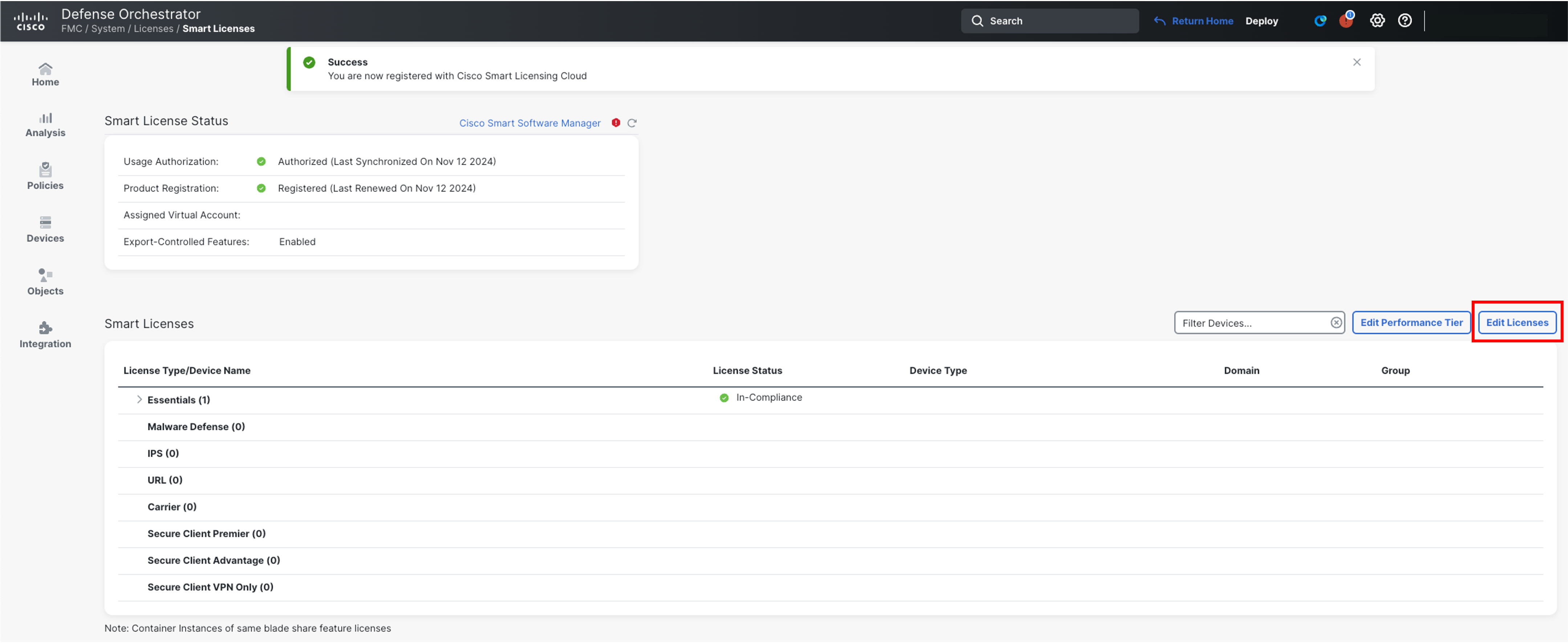
After a short time, verify the status shows Authorized and Registered

-
Click Edit Licenses on far right to add the device specific licenses
-
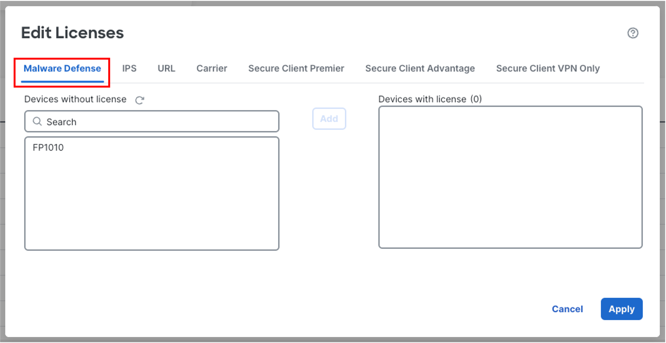
The Malware Defense tab should already be selected in the Edit Licenses pop-up. If not, select this tab before moving to the next step.
-
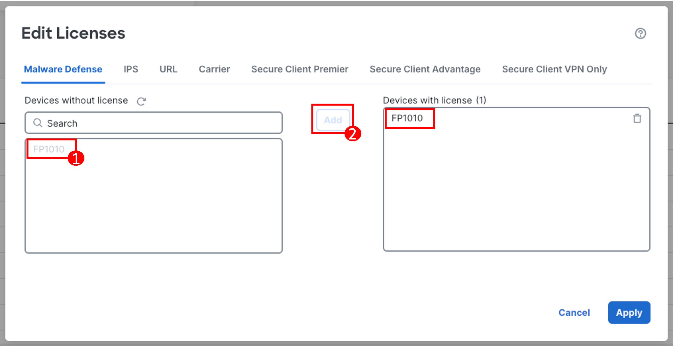
Select your device on the left and click Add to move it to right under Devices with license section.
-
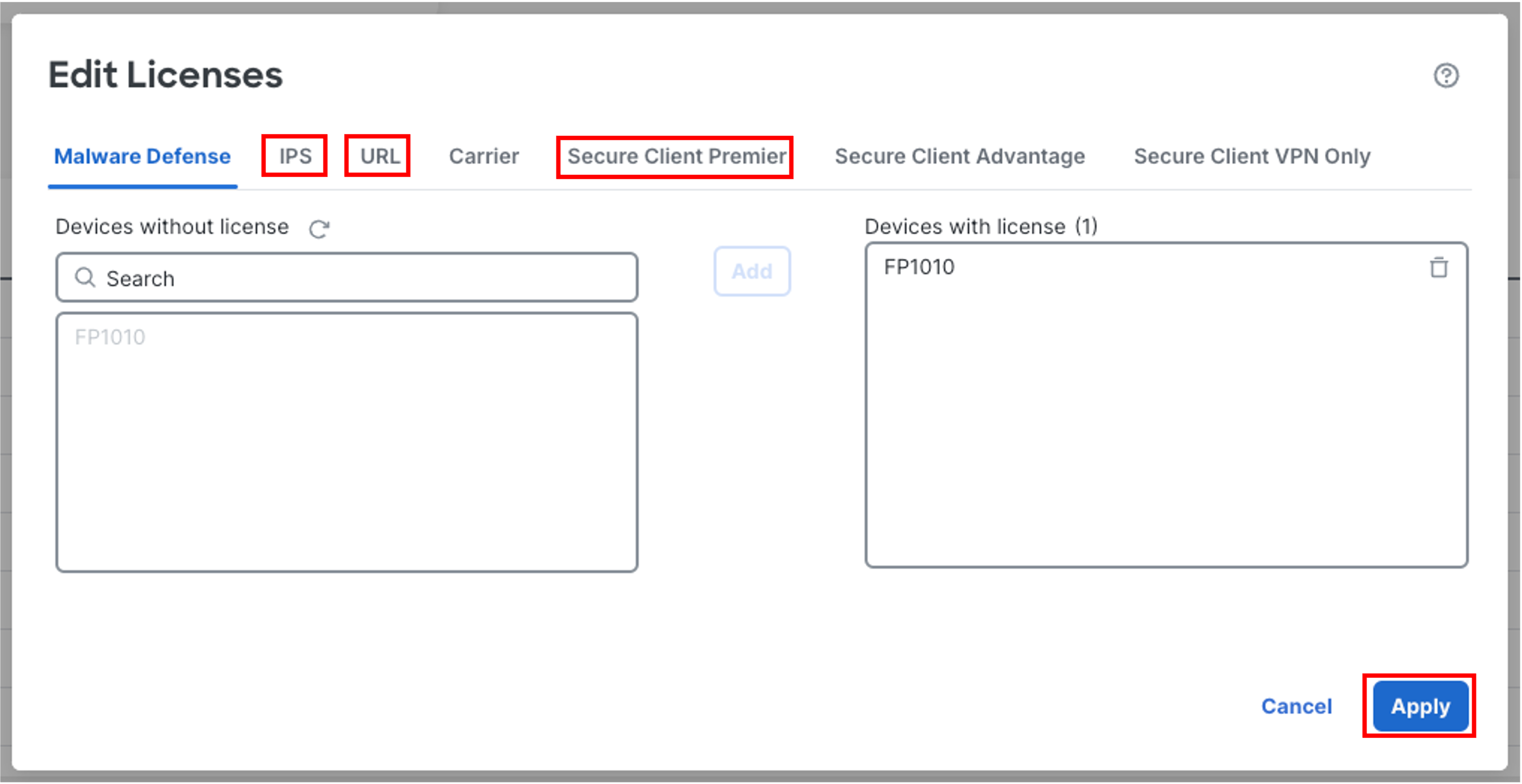
Repeat the same steps above in Step 10 for IPS, URL and Secure Client Premier. Once licenses are added for all the four features, click Apply
Summary
The concludes the steps required to configure the Firewall 1010 to be used as a security appliance in your office/home network. Though not all the security capabilities are covered in this task, the configuration on this device can be used as a baseline for demonstration purposes and you can configure additional security features to enhance the security posture.
📚Additional Resources
Updated about 1 year ago


