Scenario 4 - PBR with SGT/User Identity
Policy Based Routing provides administrators with the flexibility to route traffic based on certain parameters of the packet rather than just using the destination IP address. In the previous versions, we had introduced PBR based on IP addresses and port numbers and then added the option to match the application to route the traffic. In this version, we add additional options to route the traffic based on the user’s SGT or their identity/group information from AD. These options provide more flexibility to the administrators on how they want to route the traffic.
Lab Tasks
These are the tasks in the scenario below. If you are familiar with the Secure Firewall you may do these on your own, or for step-by-step instructions see below.
- Task 1 - Add ISE as a RADIUS server for authenticating RAVPN users
- Task 2 - Configure RAVPN
- Task 3 - Configure Access Control Rules
- Task 4 - Add Static Routes
- Task 5 - Configure Policy Based Routing based on SGT
- Task 6 - Configure NAT Rules
- Task 7 - Verify Policy Based Routing
- Task 8 - Configure Policy Based Routing based on User Identity
- Task 9 - Verify Policy Based Routing
Lab Topology

Prerequisite - Ensure ISE is Correctly Joined to the AD Server
For this lab, Cisco ISE authenticates and authorizes the VPN users. First, we'll need to ensure that AD is correctly joined with ISE. To check, open ISE using the Quick Launch by clicking ISE Web. This will open a browser window to the ISE login screen.
-
The credentials are pre-filled, click Login.
-
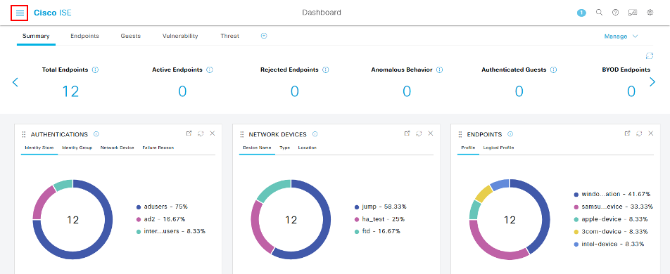
Click the three lines in the top left of the screen to open up the Navigation panel.
-
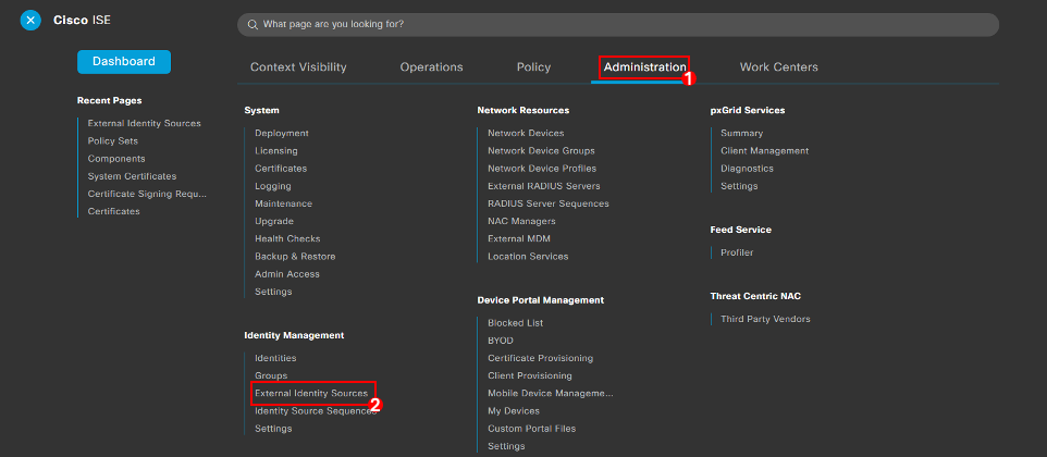
Navigate to Administration > External Identity Sources.
-
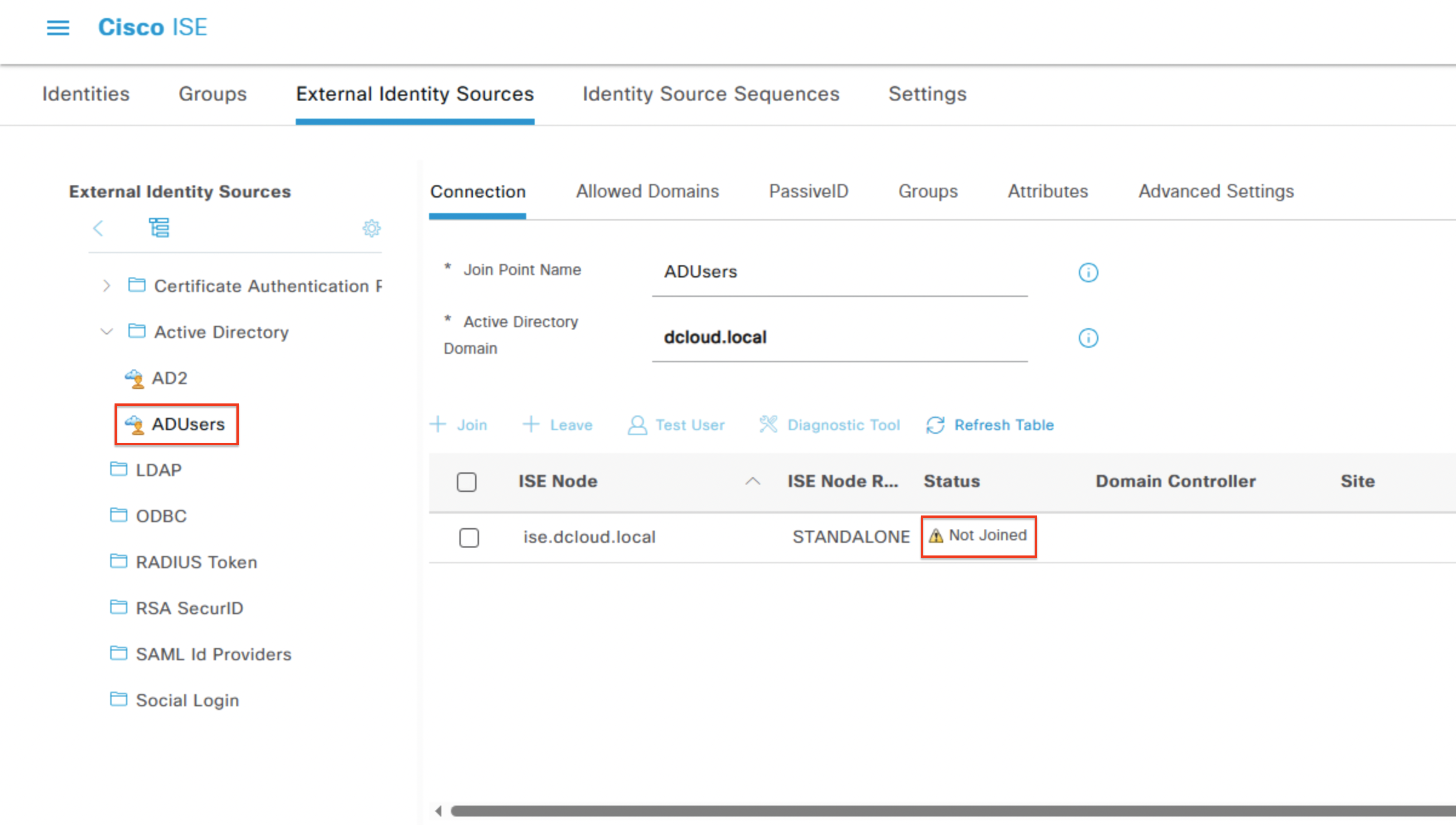
Click ADUsers on the left drop-down menu and check the Status column. The status should show as Not Joined.
Note
If the status column displays Operational, then move onto Task 1 - Add ISE as a RADIUS Server for Authenticating RAVPN Users.
-
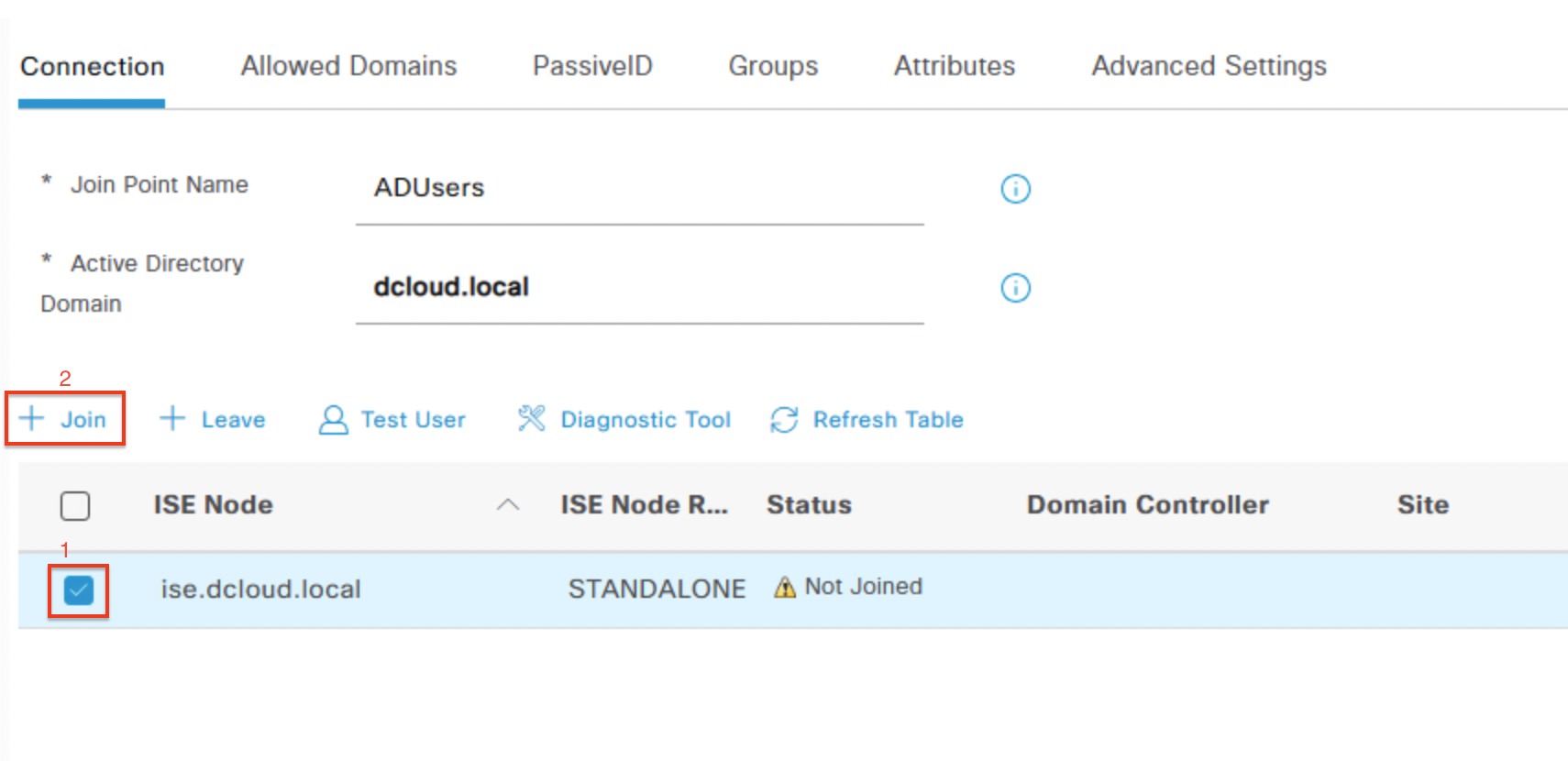
Click the checkbox for ise.dcloud.local, then click + Join.
-
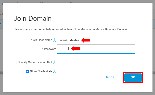
In the Join Domain dialog box enter the following credentials:
-
AD User Name: administrator
-
Password: C1sco12345
-
Click OK.
-
-
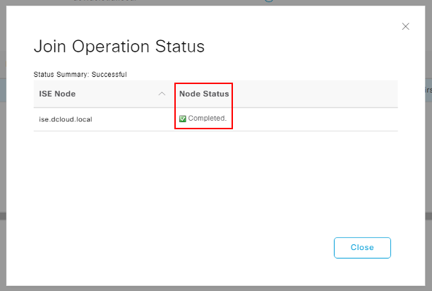
A dialog box will pop up showing a Completed status in the Node Status column.
-
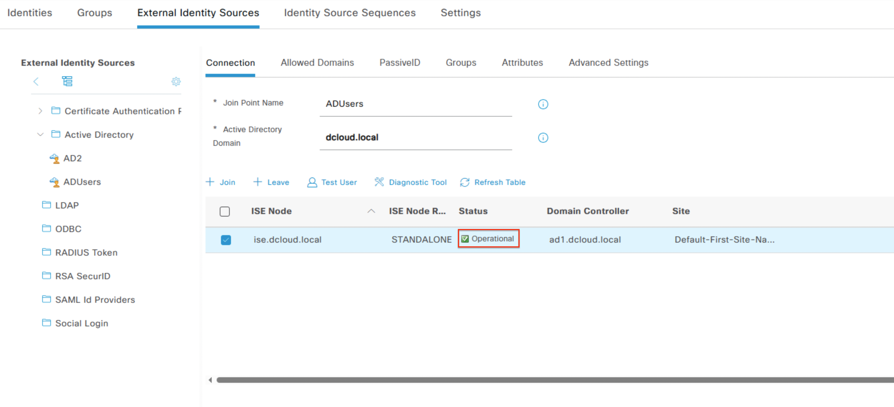
Click Close and in the External Identity Sources menu, under the Status column ensure that the value is shown as Operational.
-
Continue to Task 1 - Add ISE as a RADIUS Server for Authenticating RAVPN Users.
Task 1 - Add ISE as a RADIUS server for authenticating RAVPN Users
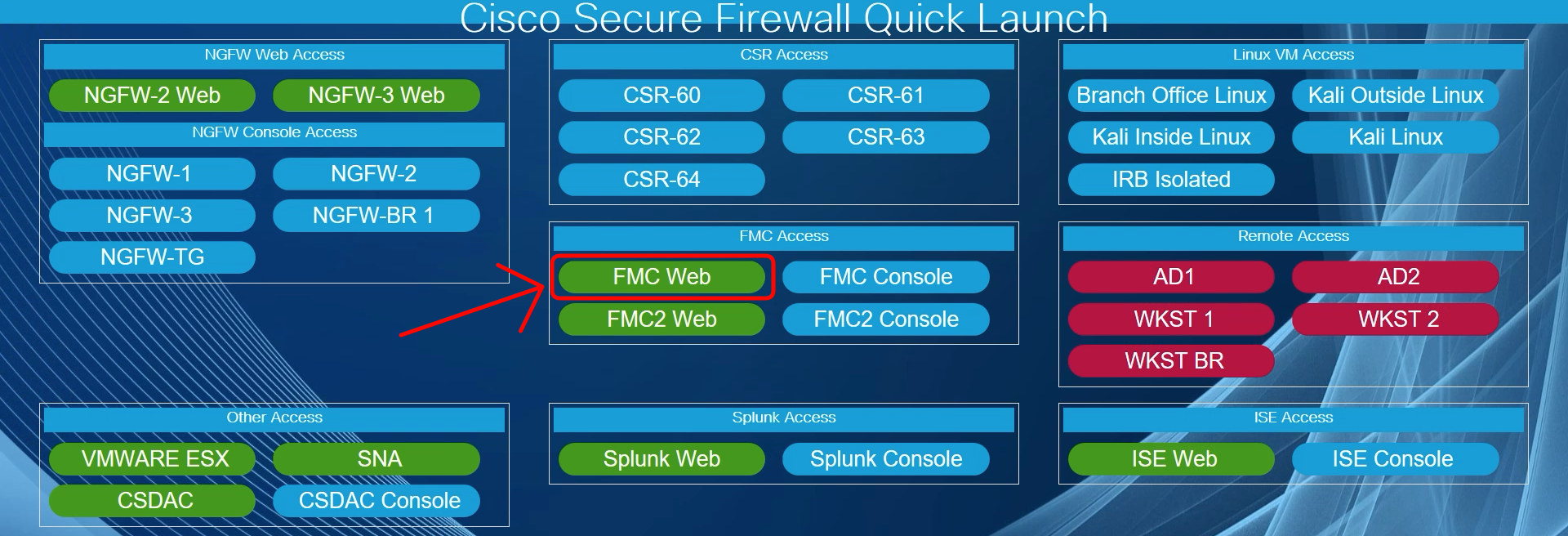
- Using the Quick Launch or the Google Chrome browser connect to the FMC web UI.
Login as admin/C1sco12345. These credentials should be pre-populated in the browser.
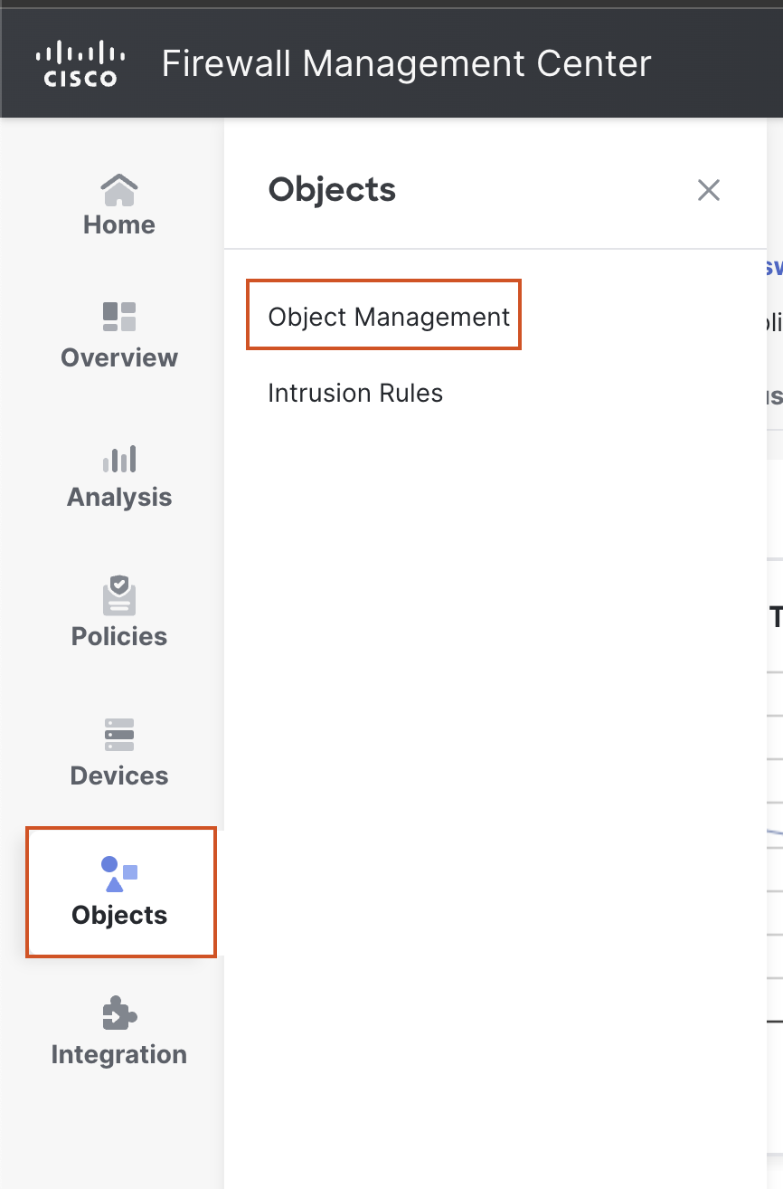
- Navigate to Objects > Object Management. In the left bar, go to AAA Server > RADIUS Server Group, then click on Add RADIUS Server Group.

- In the Pop-up box, configure the RADIUS server details as follows:
- Name: ISE
- Click the + Sign next to RADIUS Servers and provide the following details:
- IP Address/Hostname: 198.19.10.130
- Key: C1sco12345
- Leave other settings as default and click on Save.
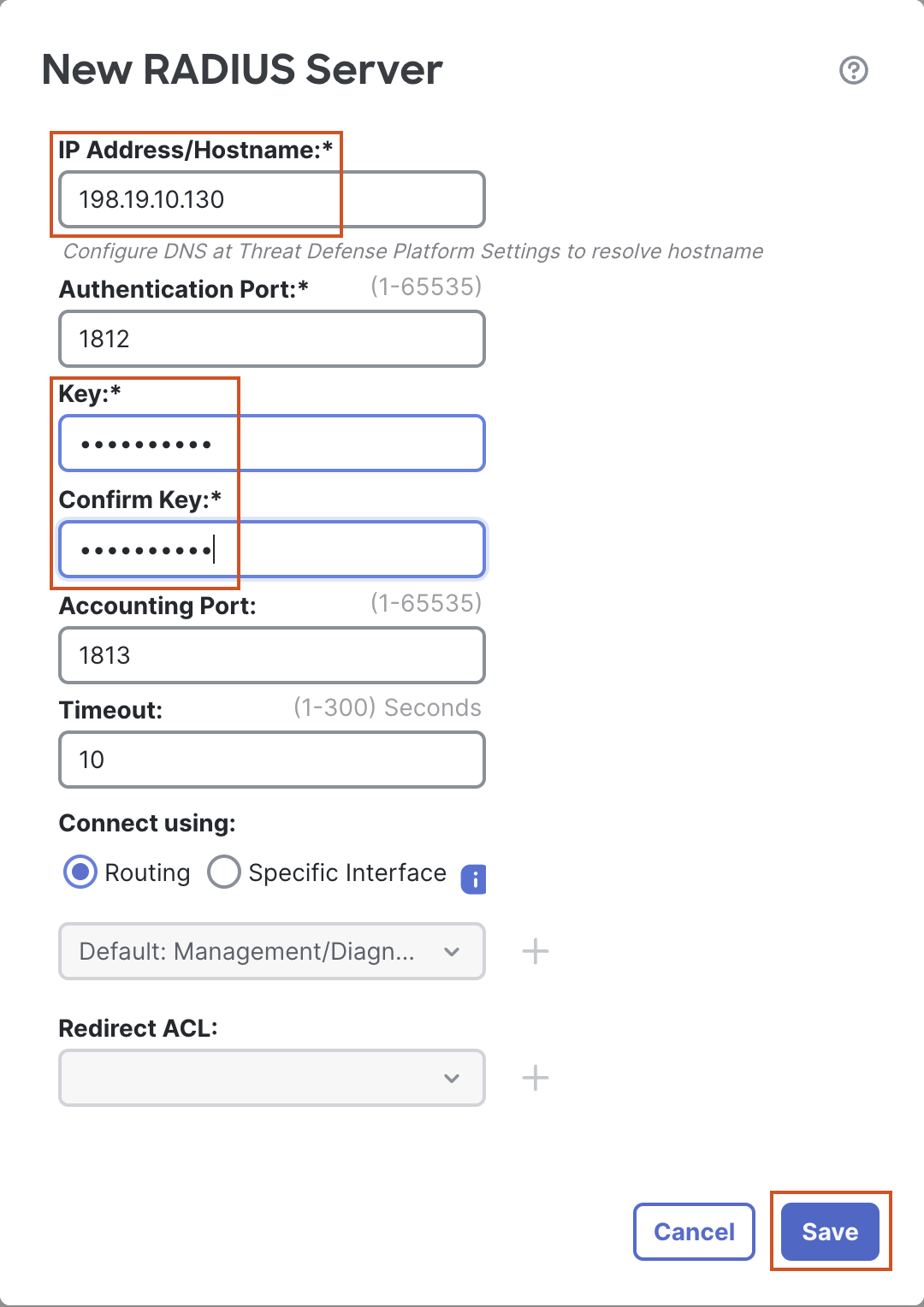
- Leave All other settings as default and click on Save.
Task 2 - Configure RAVPN
-
Navigate to Devices > VPN > Remote Access and click on Add. The Remote Access VPN wizard will open up.
-
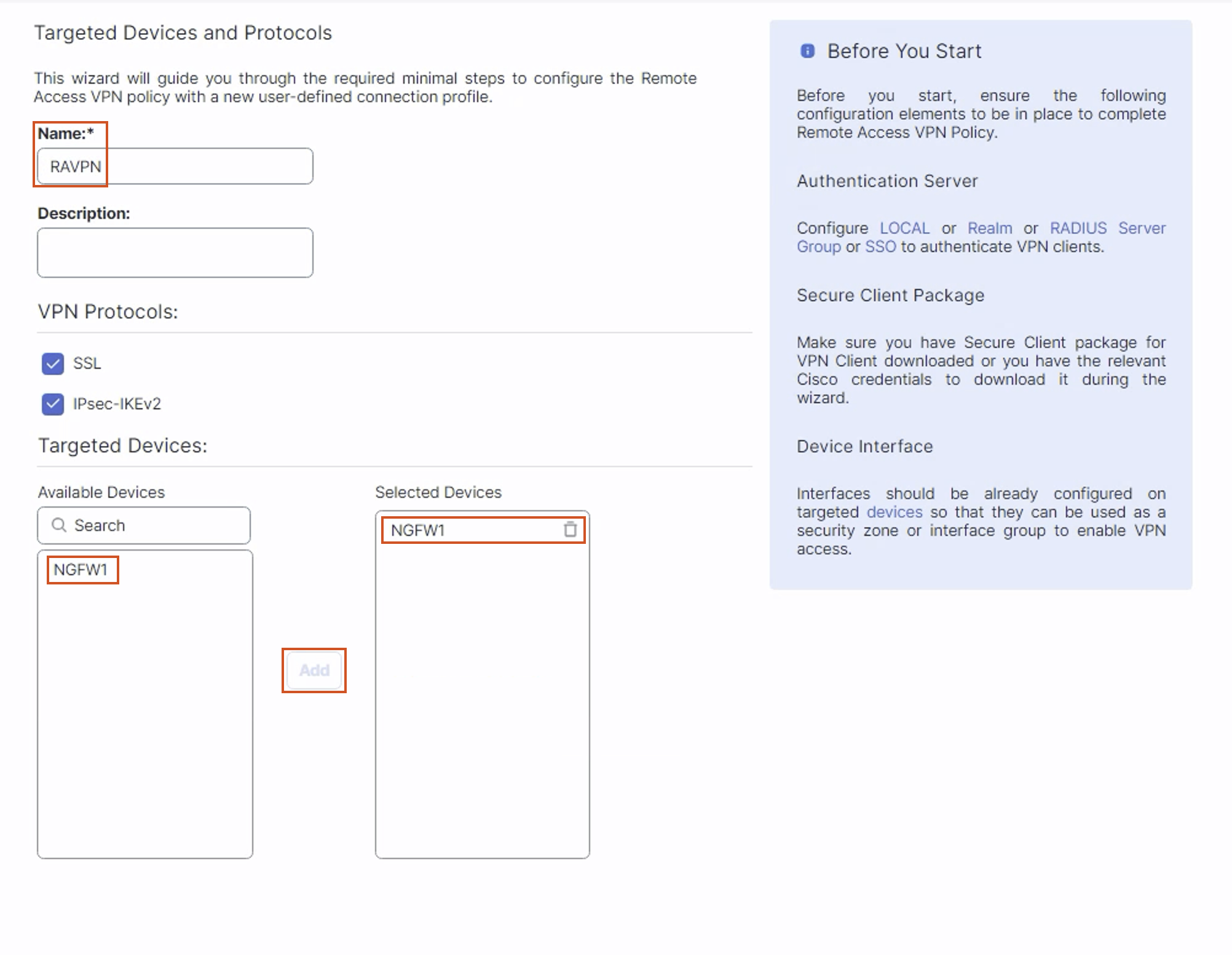
In the Policy Assignment tab configure the details as below:
- Name: RAVPN
- In the Targeted Devices Section, select NGFW1, then click on Add to move NGFW1 to the Selected Devices Section.
- Leave Other Settings as default and click Next.
-
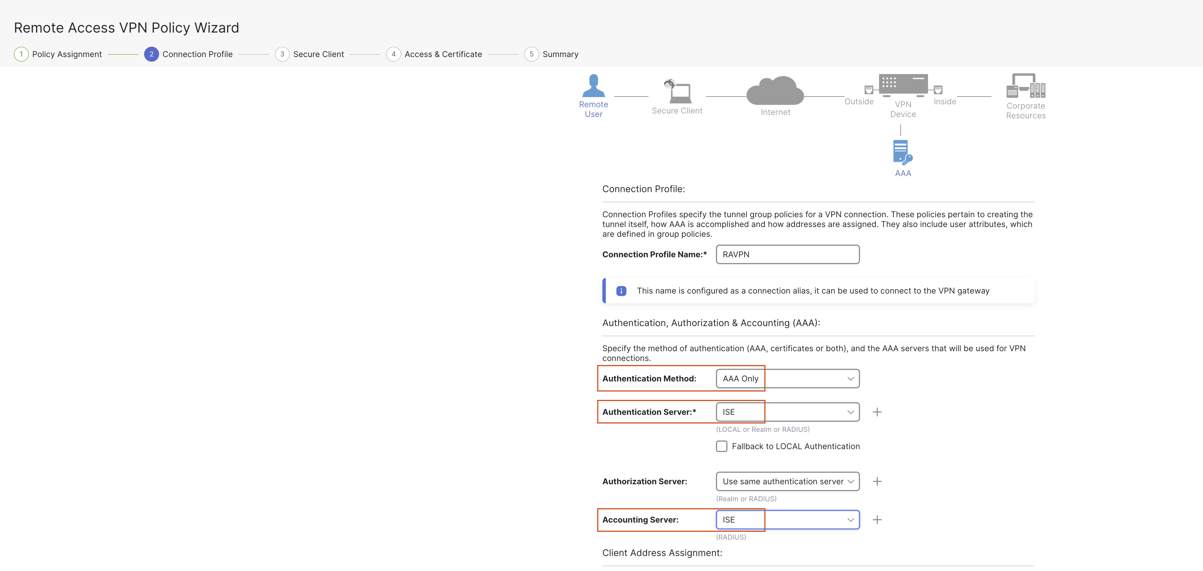
In the Connection Profile tab configure the details as below:
3a. Connection Profile Name: RAVPN (will be pre-filled from the Name in the previous tab)
3b. Authentication Method: AAA Only
3c. Authentication Server: Select "ISE" from the drop down (the server created in the previous step).
3d. Accounting Server: Select "ISE" from the drop down (the server created in the previous step).
3e. Client Address Assignment:
-
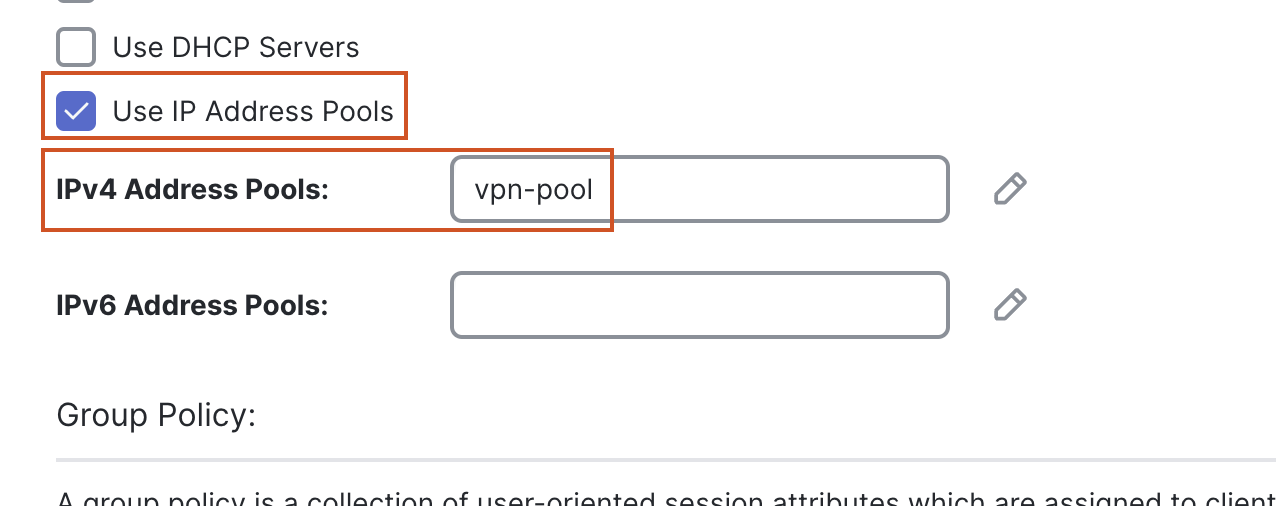
The "Use IP Address Pools" checkbox will be selected by default. We will create an IPv4 address pool in the next step.
-
Click on the pencil (edit) icon next to the IPv4 Address Pools.
-
In the pop up box, click on the + sign next to Available IPv4 Pools.
- In the pop up box, provide the following details:
- Name: vpn-pool
- IPv4 Address Range: 172.16.1.2-172.16.1.254
- Mask: 255.255.255.0
- Leave other settings as default and click Save.
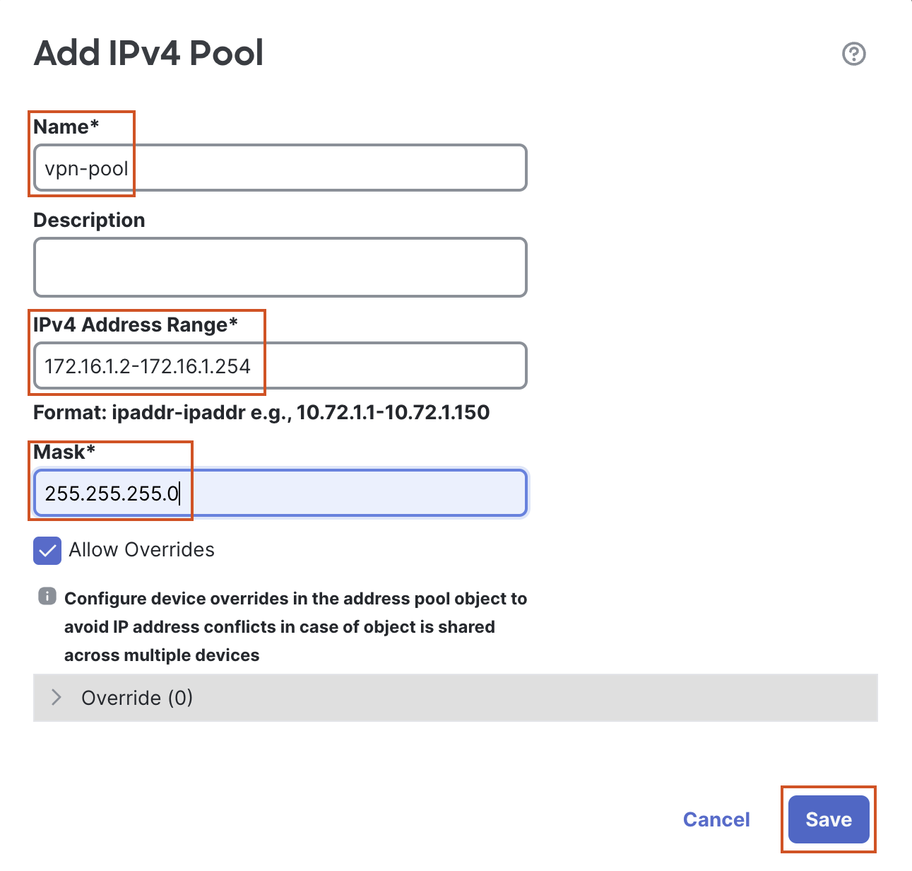
- In the pop up box, provide the following details:
-
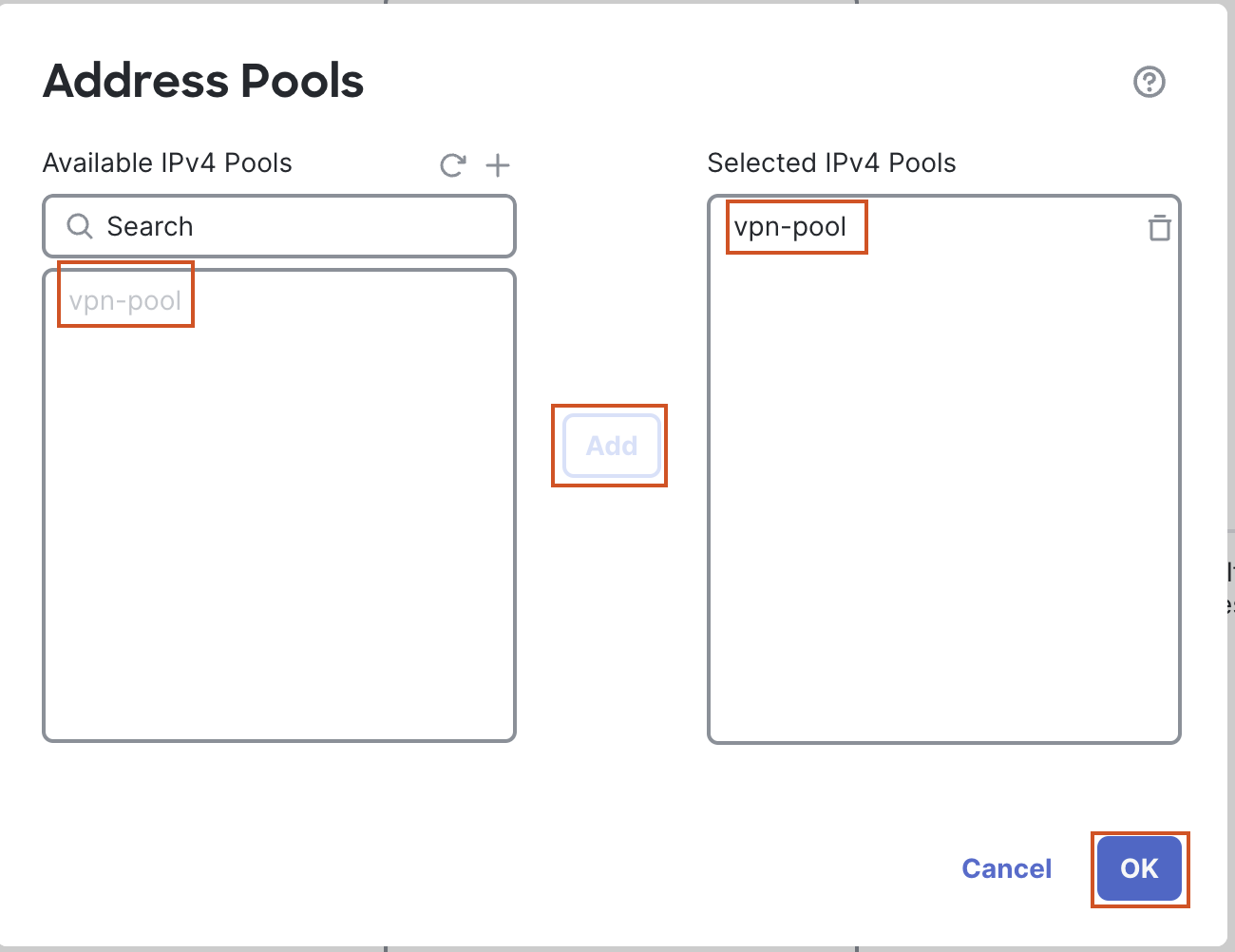
Select the newly created address pool and click on Add to move the pool to the Selected IPv4 Pools section.
-
Click on OK.
3f. Group Policy:
-
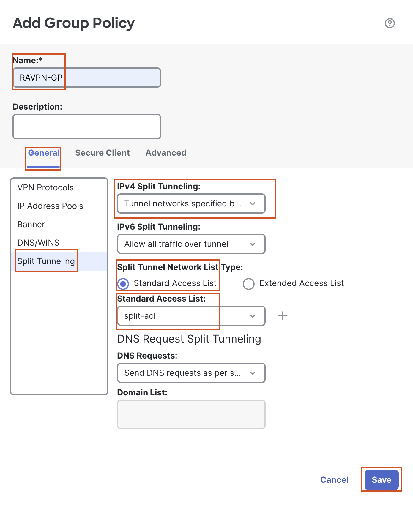
Click on the + sign next to Group Policy to create a new group policy. In the pop up box configure the following details:
-
Name: RAVPN-GP
-
In the General Tab:
-
Go to the Split Tunneling section on the left:
-
Change IPv4 Split Tunneling to "Tunnel networks specified below" from the dropdown
-
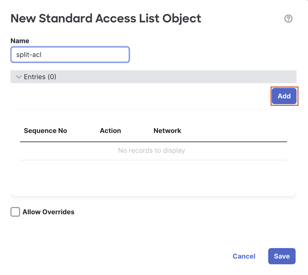
Click on the + sign next to Standard Access List. In the pop up configure the following details:
-
Name: split-acl
-
Click on Add to add a new ACE. In the pop up box to add an ACE, click on the + sign next to Available Network to add a new object.
-
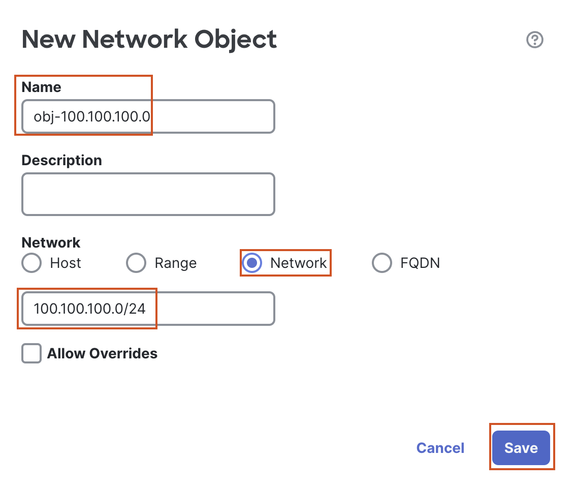
In the pop up box to add a New Network Object, configure the following details:
- Name: obj-100.100.100.0
- Select the Radio button next to Network.
- In the text box below enter 100.100.100.0/24.
- Click Save to save the object.
-
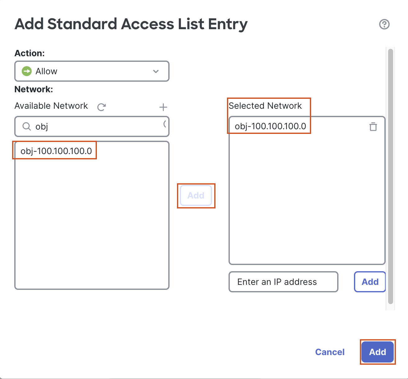
In the Available Network Section select the newly created object (obj-100.100.100.0), and click on Add to move the object to the Selected Network section. Click on Add below to add the access list entry to the access list.
-
-
Click on Save to save the Access List, and select the ACL from the drop down.
-
-
-
-
-
-
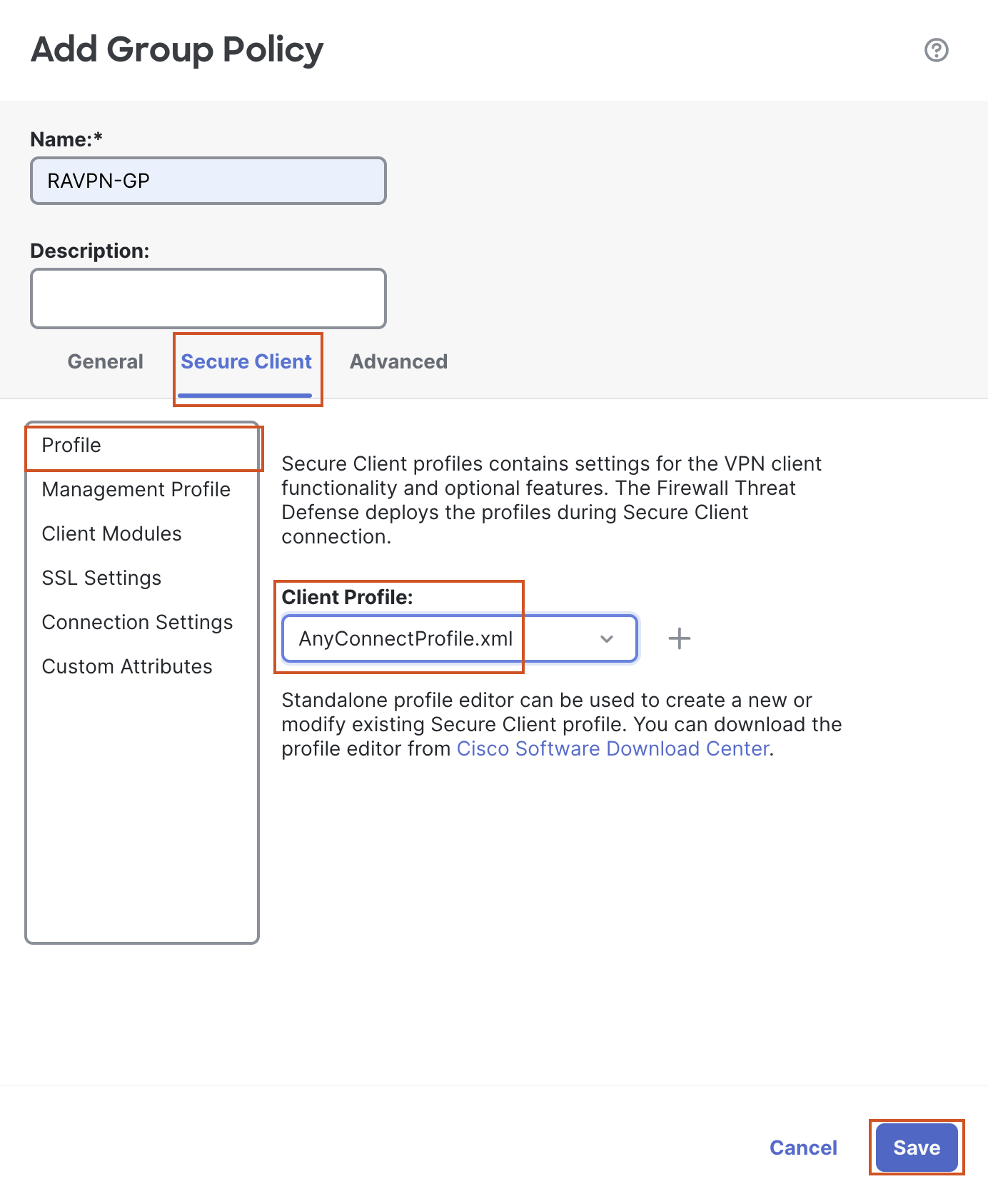
Leave all other settings at default and move to the Secure Client Tab.
-
Select the Profile section on the left.
-
Click on the + sign next to Client Profile
-
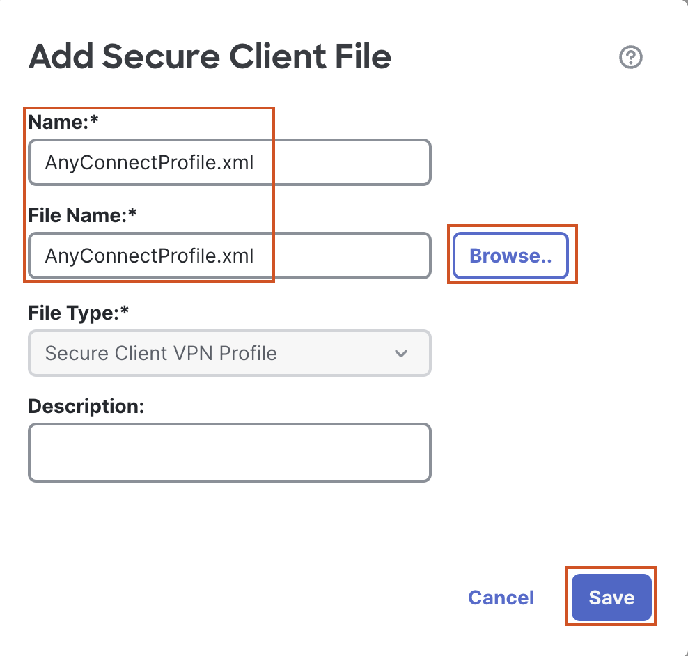
Click on Browse
- In the pop up box, go to Desktop > RAVPN Files and select the AnyconnectProfile.xml file and click on Save.
- In the pop up box, go to Desktop > RAVPN Files and select the AnyconnectProfile.xml file and click on Save.
-
Select the AnyConnectProfile.xml from the drop down.
-
-
-
Leave all other settings as default and click on Save to save the group policy.
-
Select the newly created group policy from the drop down and click on Next.
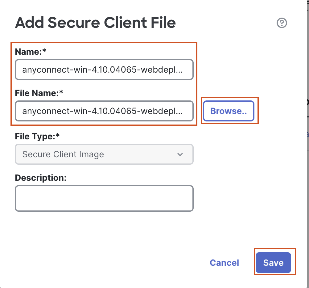
- In the Secure Client Tab, click on the + sign to add the AnyConnect webdeploy image.In the pop up box, click on Browse, and go to Desktop > RAVPN files and select the anyconnect-win-4.10.04065-webdeploy.pkg package. Click on Save.
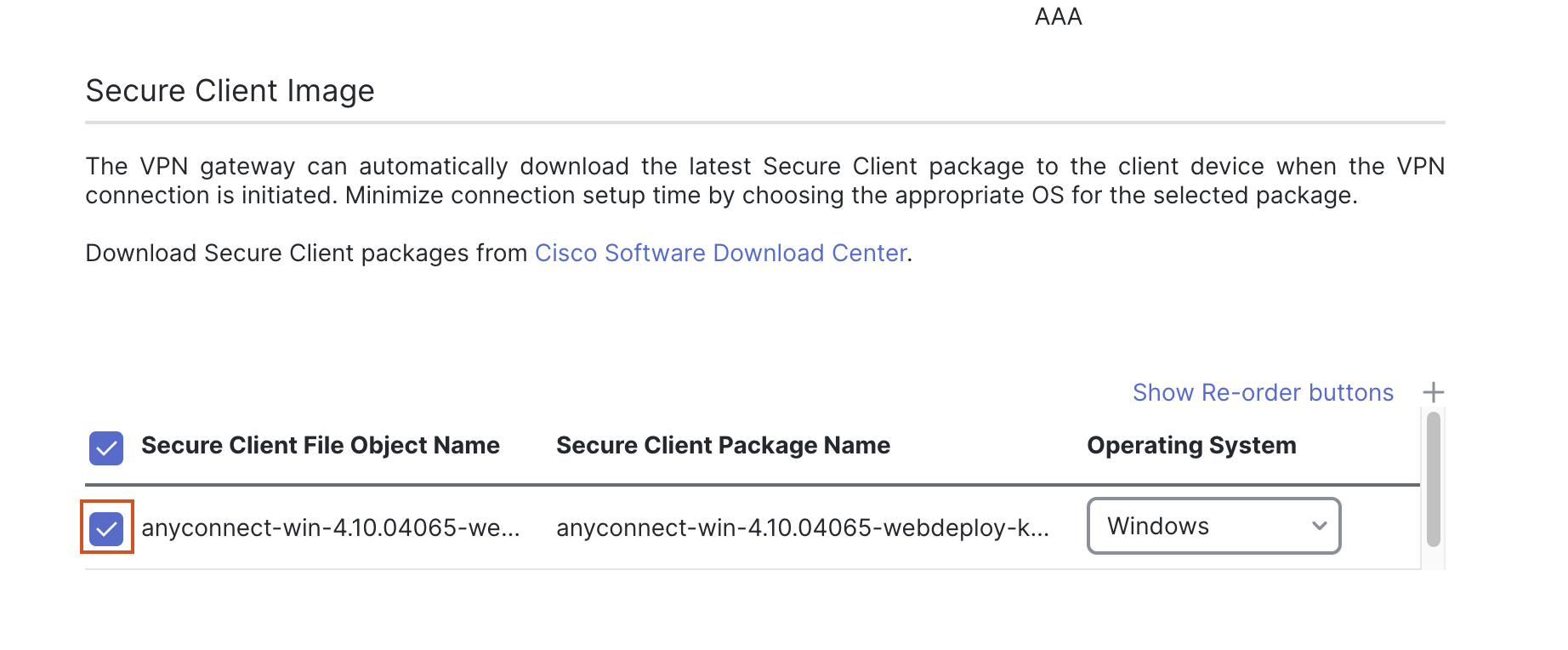
- Select the check box next to the uploaded image and click on Next.
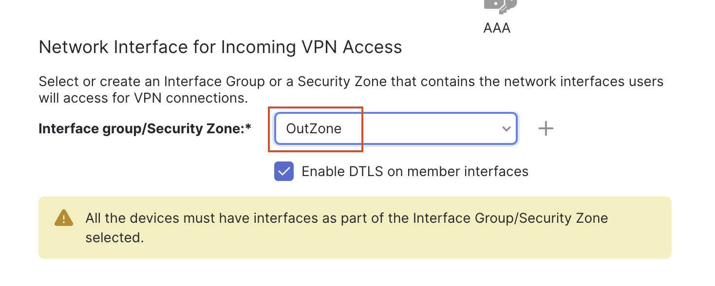
- In the Access and Certificate Tab
- From the drop down next to Interface Security/Security Zone, select OutZone as the zone.
-
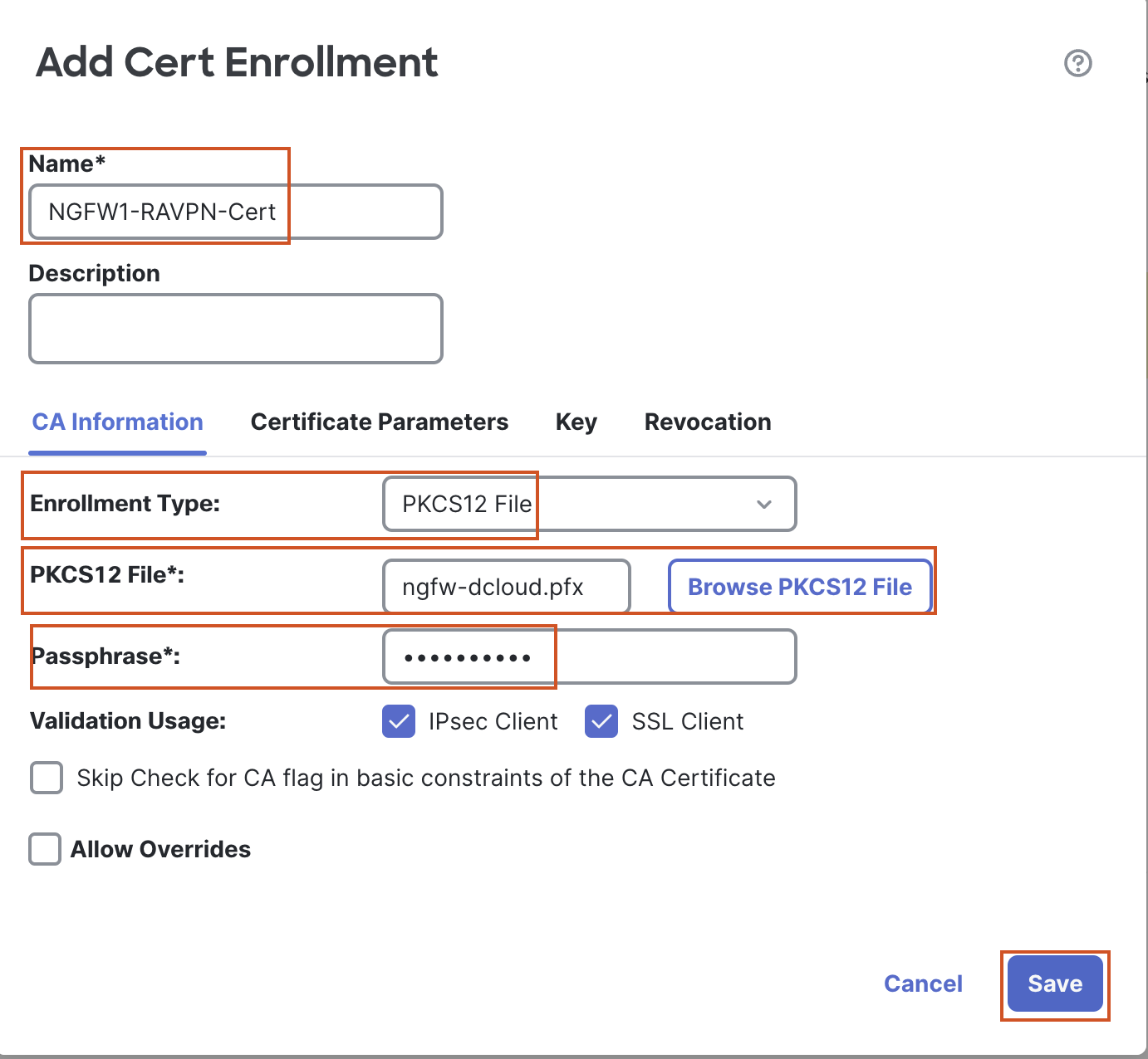
Click the + sign next to Certificate Enrollment. In the pop up box, configure the following details:
- Name: NGFW1-RAVPN-Cert
- Change Enrollment Type to PKCS12 File.
- Click on Browse PKCS12 File and go to Desktop > Certificates > Lab Certificates > Other Certificates and select “ngfw-dcloud.pfx”.
- Use the passphrase "C1sco12345".
- Leave other settings as default and click on Save.
-
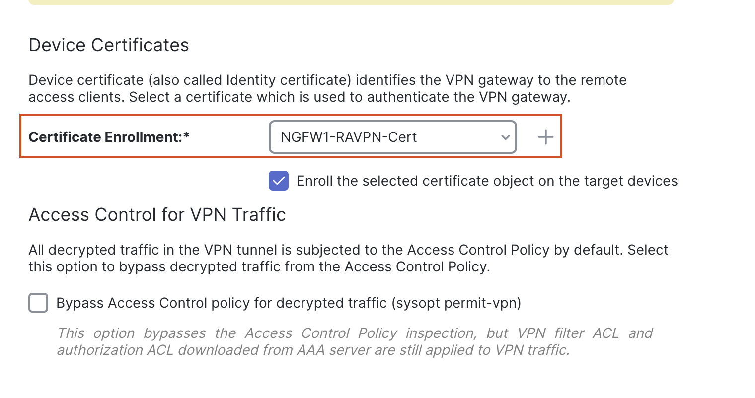
Select the certificate from the drop down.
- Click on Next.
- Click on Finish.
Task 3 - Configure Access Control Rule
- Go to Policies > Access Control > Access Control and click the Pencil (edit) icon next to NGFW1.
-
Click on Add Rule.
-
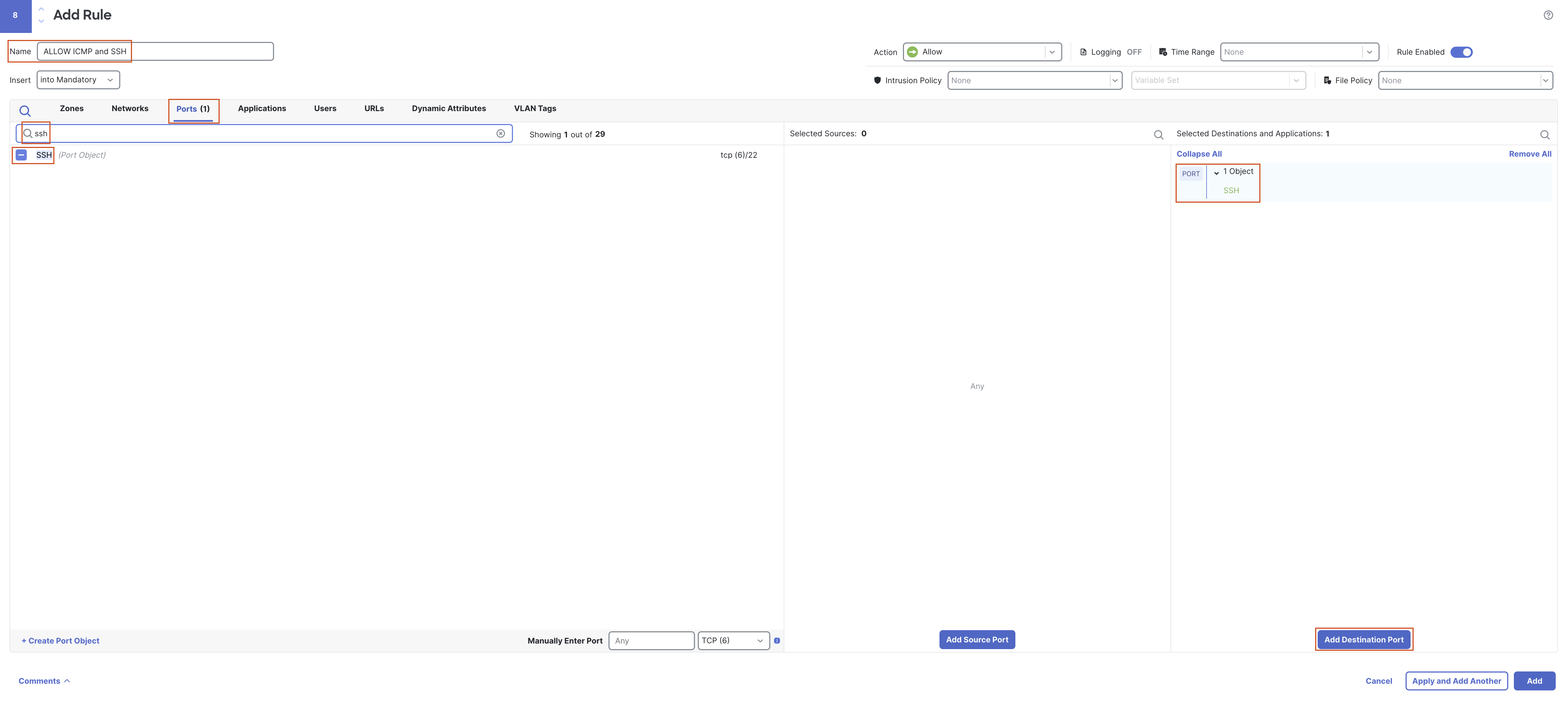
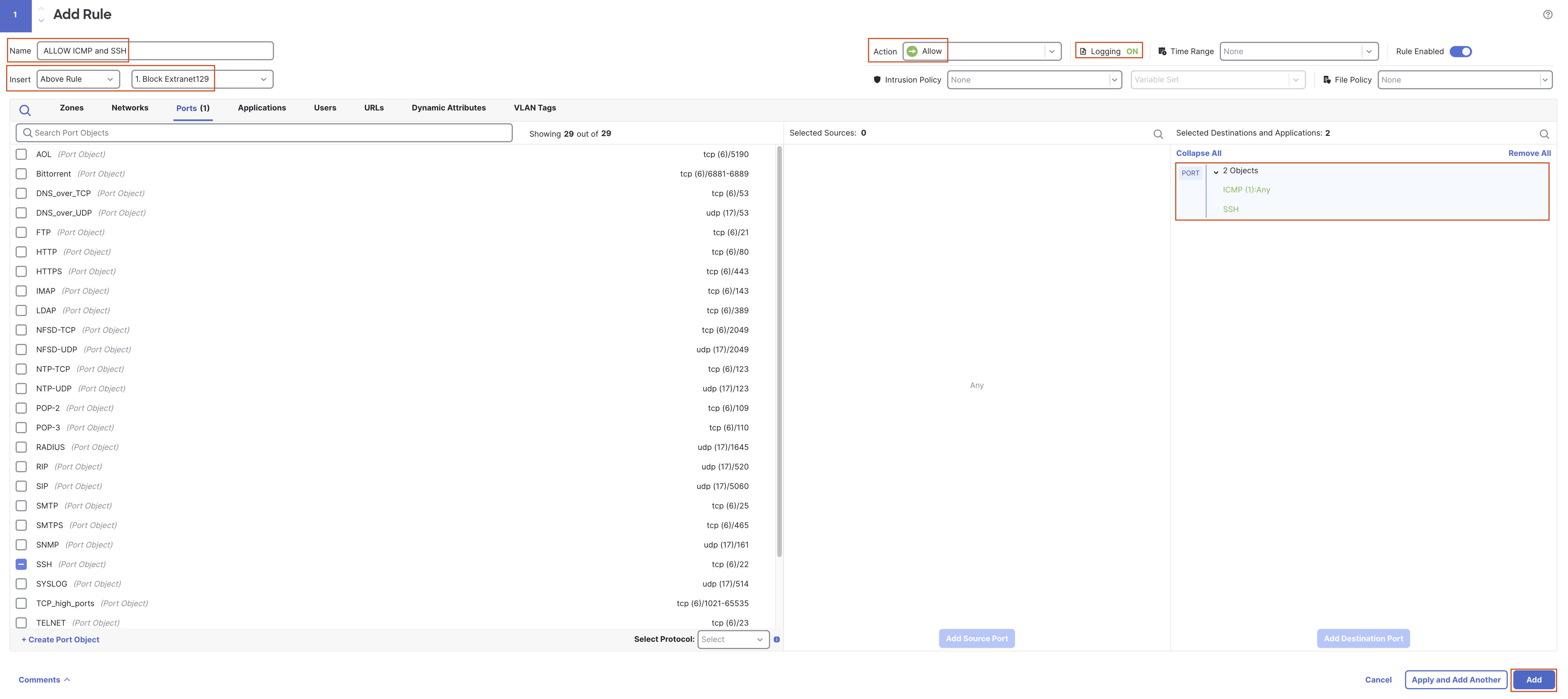
Name: Allow ICMP and SSH
-
Go to the Ports tab.
-
In the Search Port Objects field enter "SSH", select SSH and click on Add Destination Port.
-
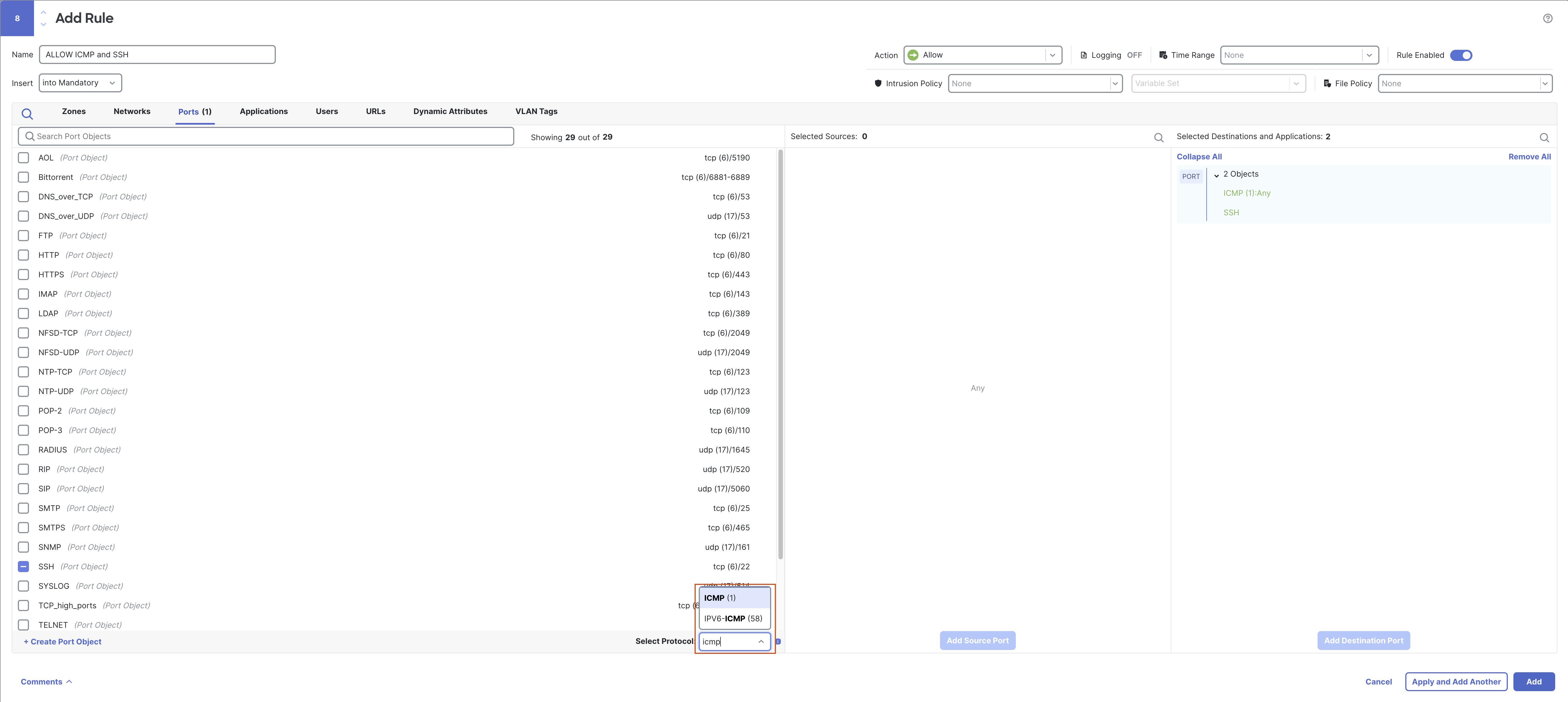
Remove "SSH" from the search box, and change the protocol to ICMP.
Note
Since this is a lab environment we have allowed SSH and ICMP from all source/zones. This may not be the case in production environment. The idea here is to allow the traffic to show how Policy Based Routing will work.
-
Leave Type as Any and click on Add to Destination.
-
In the Insert section change to “Above Rule” and select rule number 1 so that the rule gets added to the top.
-
Enable logging at the end of the connection.
-
Apply the rule and Save the changes.
-
-
Task 4 - Add Static Routes
- Go to Devices > Device Management and click the Pencil (edit) icon next to NGFW1.
- Go to the Routing Tab and go to Static Route in the left tab.
-
Click on + Add Route to add a new route.
-
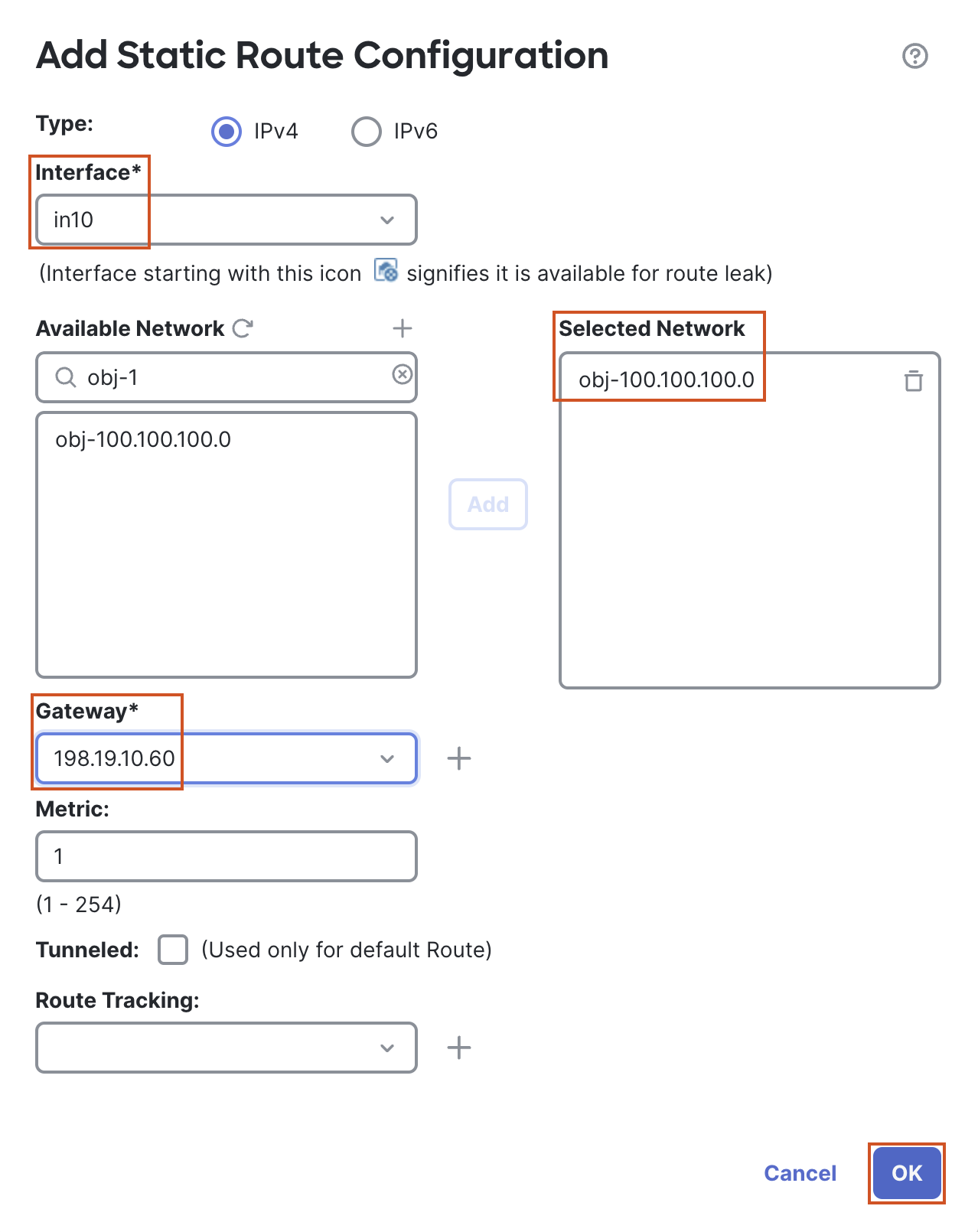
In the pop up box, configure the following details:
- Interface: in10
- In the Available Network section search for "obj-100.100.100.0" and move it to the Selected Network section
- Gateway: 198.19.10.60
- Click on OK to Add the route
- Click on + Add Route to add another route.
-
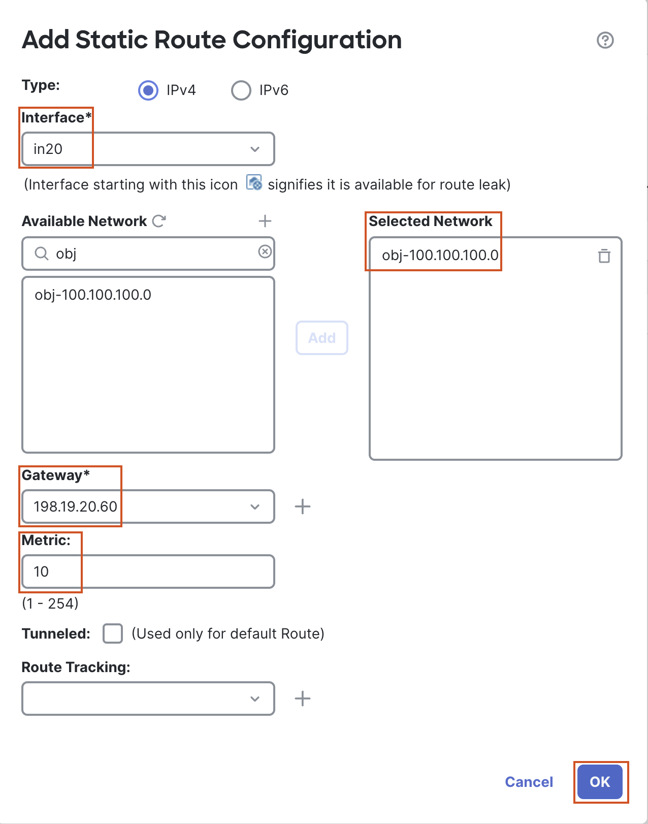
In the pop-up box, configure the following details:
- Interface: in20
- In the Available Network section search for "obj-100.100.100.0" and move it to the Selected Network section.
- Gateway: 198.19.20.60
- Change the Metric from 1 to 10.
- Click on OK to Add the route.
- Click on Save to save the changes.
Task 5 - Configure Policy Based Routing based on SGT
- Go to Objects > Object Management > Access List > Extended and click on Add Extended Access List to add an access list that will be used in Policy Based Routing.
-
In the pop up box, configure the following details:
-
Name: PBR-ACL
-
Click on Add.
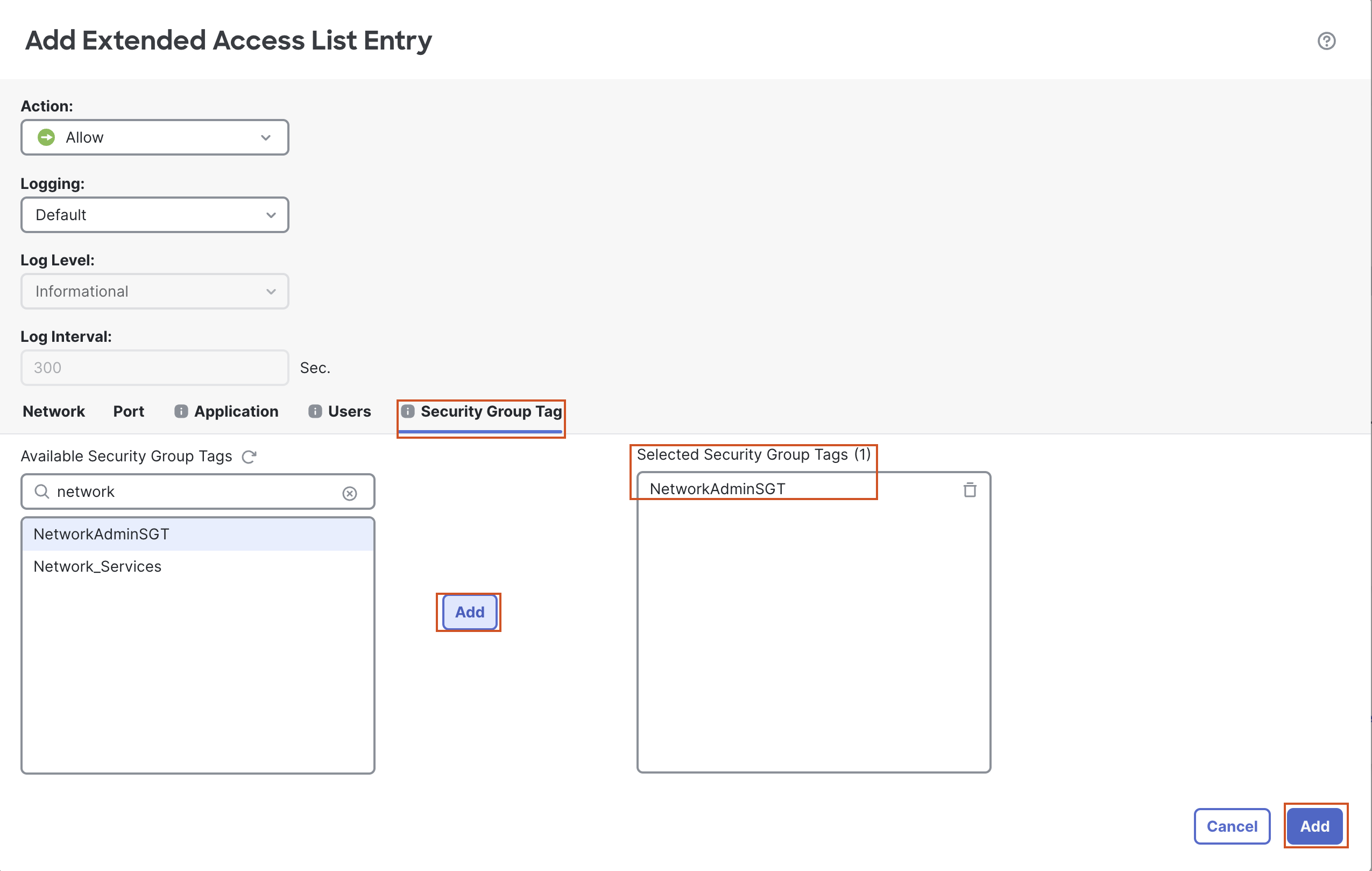
- Go to the "Security Group Tag" tab, search for "NetworkAdminSGT" and move it to the Selected Security Group Tags section.
- Click on Add to add the entry.
-
Click on Save to save the ACL.
-
Note
There may small corner-cases where the Security Group Tags are not populated in the Extended Access List Entry window. To fix this, we simply need to refresh the connection between FMC and ISE. Head over to Integration > Other Integrations > Identity Sources.
The radio button for ISE will be selected. Click the radio button next to None, then click Save.
In the confirmation dialog, click Confirm. Now, to refresh the connections we'll need to simply add ISE back as an Identity Source by selecting the radio button next to Identity Services Engine and clicking Save.
Now, repeat the steps in step 1 and the Security Group Tags will be populated in the Extended Access List Entry window.
- Go to Devices > Device Management and select the pencil icon next to NGFW1.
-
Go to the Routing tab and then Policy Based Routing.
-
Click on Add.
-
In the pop up, select "outside" as the Ingress Interface.
-
Click on Add to add the Match Criteria and Egress Interface.
-
In the pop up box, configure the following details:
- Match ACL: Select PBR-ACL from the drop down.
- From the Available Interfaces list, select "in20" and click on the + sign next to it to move it to the Selected Egress Interfaces.
- Click on Save.
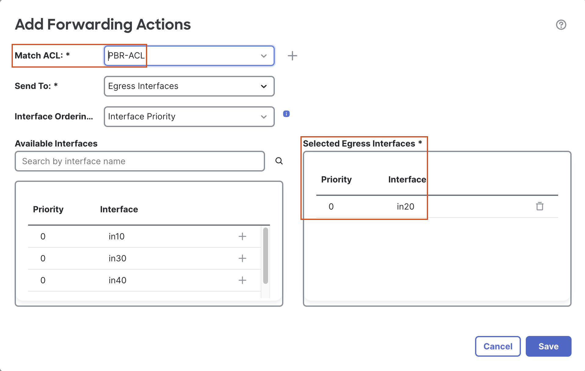
- The final entry will look like the following:
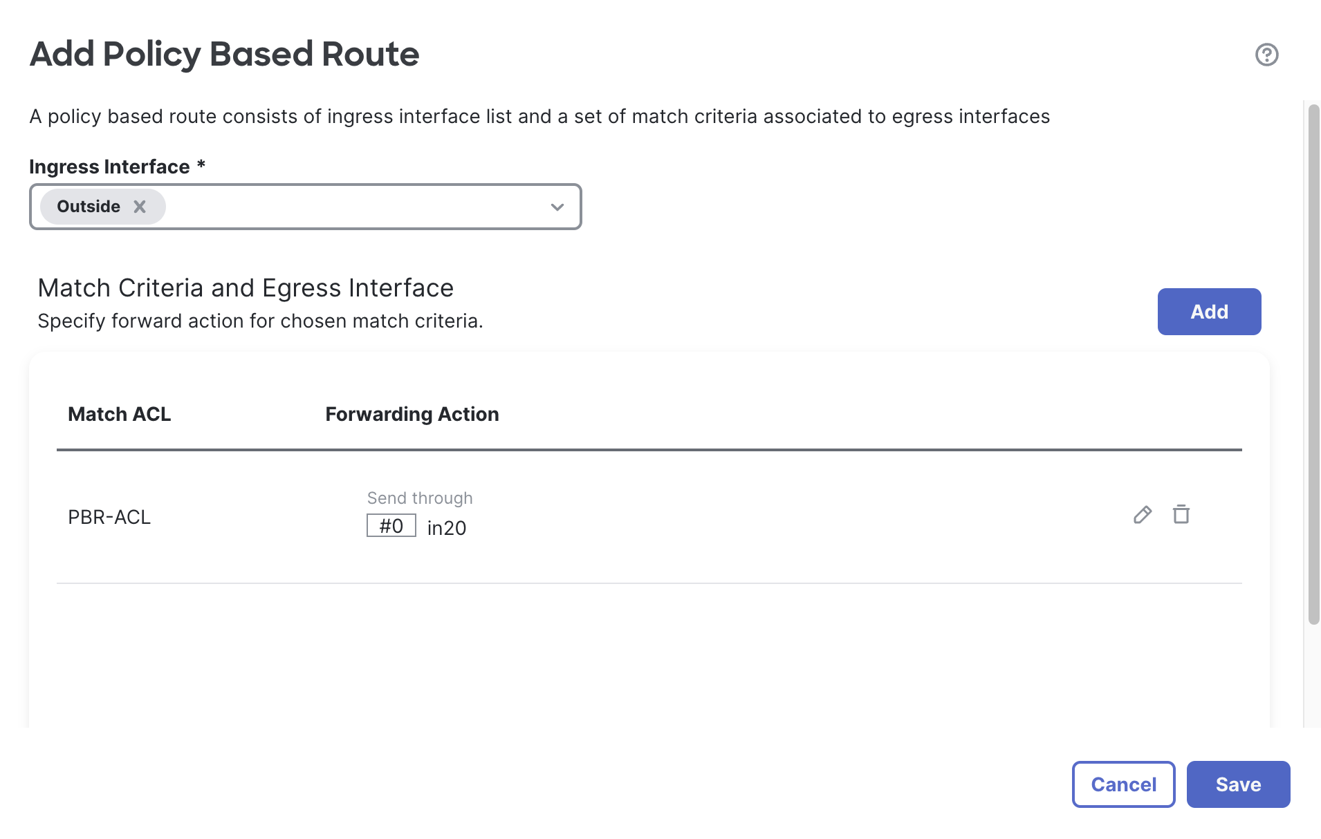
-
-
Click on Save to save the PBR entry.
-
Click on Save to save the changes.
Task 6 - Configure NAT Rules
- Go to Devices > NAT and edit the NGFW1 NAT policy.
- Click on Add Rule to add a PAT rule for traffic going through in10. In the pop up box, configure the following details:
- Select Dynamic from the "Type" drop-down menu.
- Go to Interface Objects tab:
- Configure OutZone as the Source Interface Object:
- Select OutZone under Available Interface Objects.
- Click Add to Source.
- Configure InZone1 as the Destination Interface Object:
- Select InZone1 under Available Interface Objects.
- Click Add to Destination.
- Configure OutZone as the Source Interface Object:
- Go to the Translation tab:
- Click the + sign next to Original Source and add an object for 172.16.1.0/24 by clicking Add Object:
- Name: obj-172.16.1.0
- Select the Radio button next to Network.
- In the text box below enter 172.16.1.0/24.
- Click Save to save the object.
- Select obj-172.16.1.0 in the Original Source.
- For the Translated Source select “Destination Interface IP” from the drop-down.
- Leave all other fields at default and click on OK.
- Click the + sign next to Original Source and add an object for 172.16.1.0/24 by clicking Add Object:
- Click on Add Rule to add another PAT rule for traffic going through in20.
- Select Dynamic from the "Type" drop-down menu.
- Go to Interface Objects tab:
- Configure OutZone as the Source Interface Object:
- Select OutZone under Available Interface Objects.
- Click Add to Source.
- Configure InZone2 as the Destination Interface Object:
- Select InZone2 under Available Interface Objects.
- Click Add to Destination.
- Configure OutZone as the Source Interface Object:
- Go to the Translation tab
- For the Original Source select the obj-172.16.1.0 object created earlier .
- For the Translated source select “Destination Interface IP” from the drop-down.
- Leave all other fields at default and click on OK.
- Click Save to save the changes.
- The final rules will look like this

- Deploy the policy by clicking Deploy > Deploy All.

Warning
Wait for the deployment to complete before proceeding.
Task 7 - Verify Policy Based Routing
- Using the Quick Launcher connect to the CLI of NGFW1. The credentials will be pre-populated.
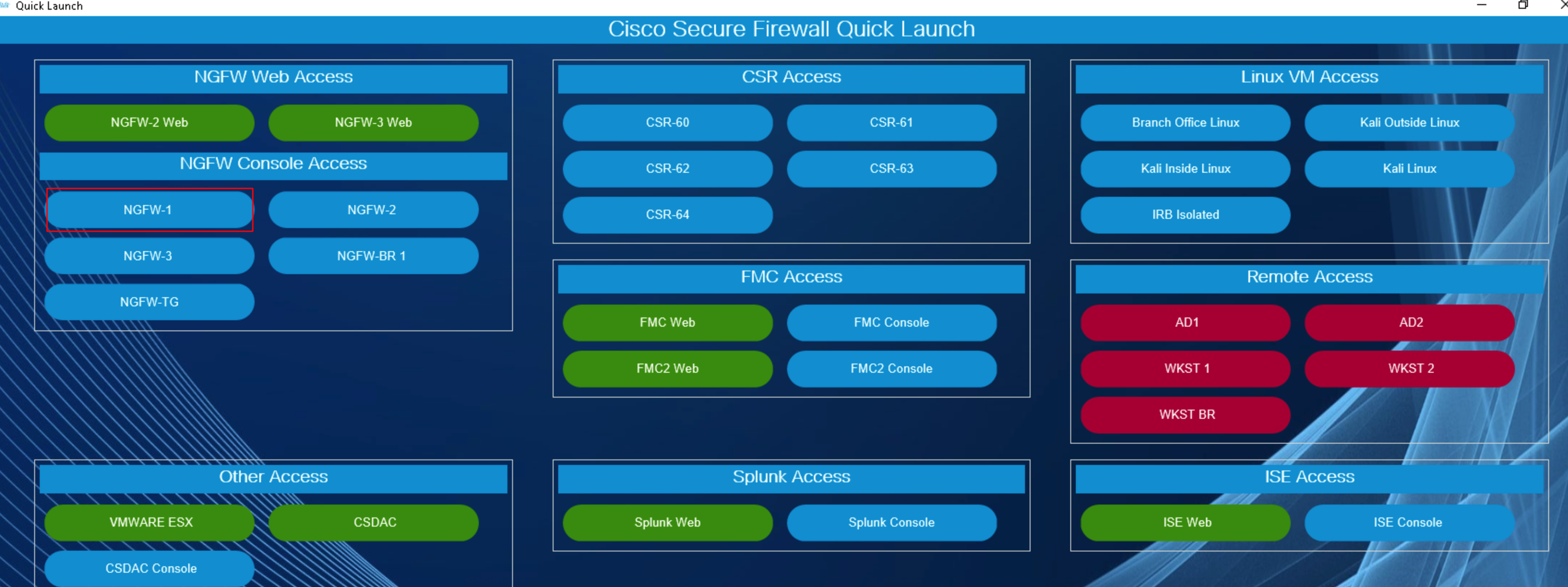
- Connect to the diagnostic CLI by using the following command:
system support diagnostic-cli
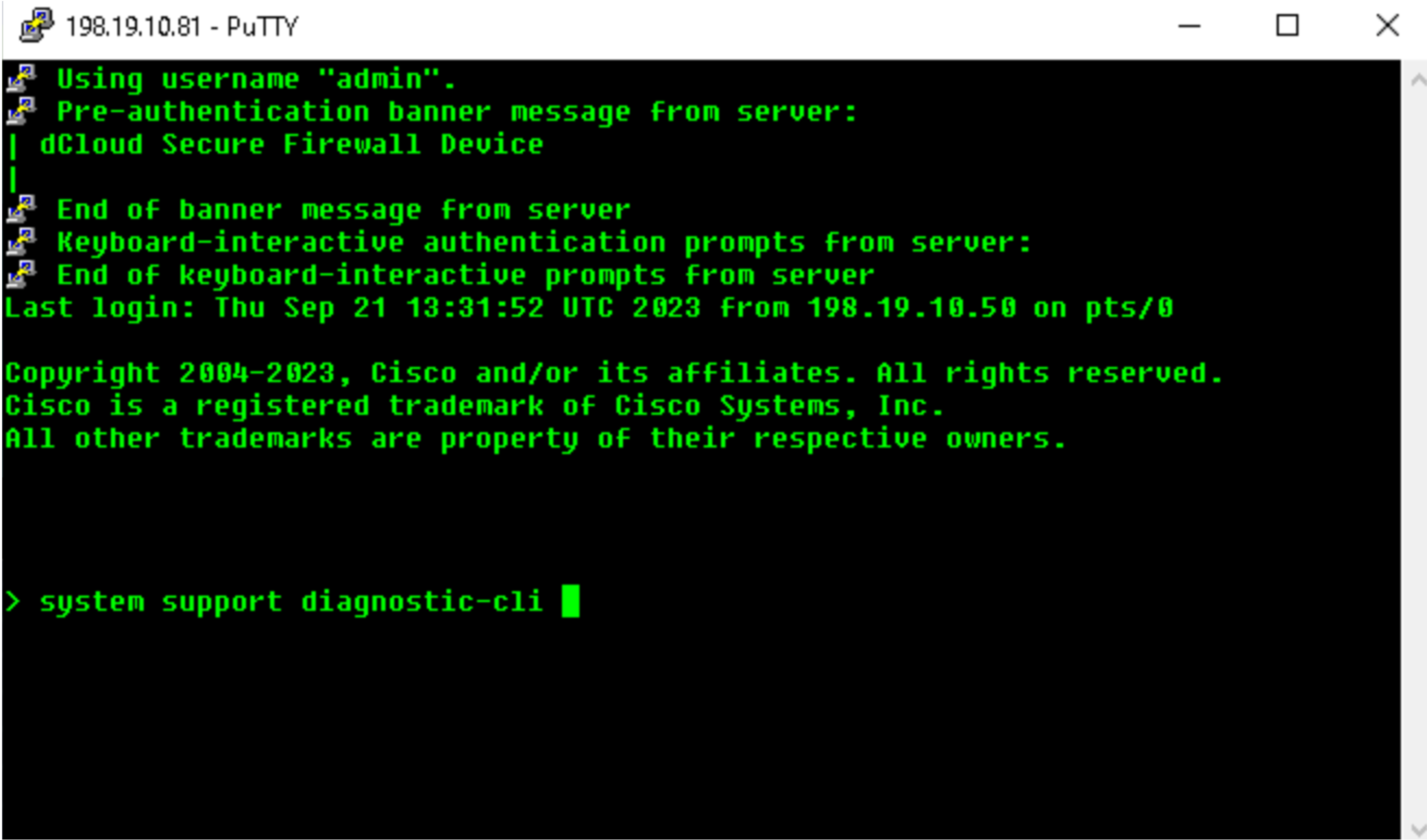
- Use the
enablecommand to log into enable mode (privileged mode) and leave the password blank. - Apply captures on in10 and in20 interfaces using the following commands:
capture cap10 interface in10 match ip host 198.19.10.1 host 100.100.100.1capture cap20 interface in20 match ip host 198.19.20.1 host 100.100.100.1

-
Next remote desktop to wkst2. We will use this workstation to RAVPN to the firewall.
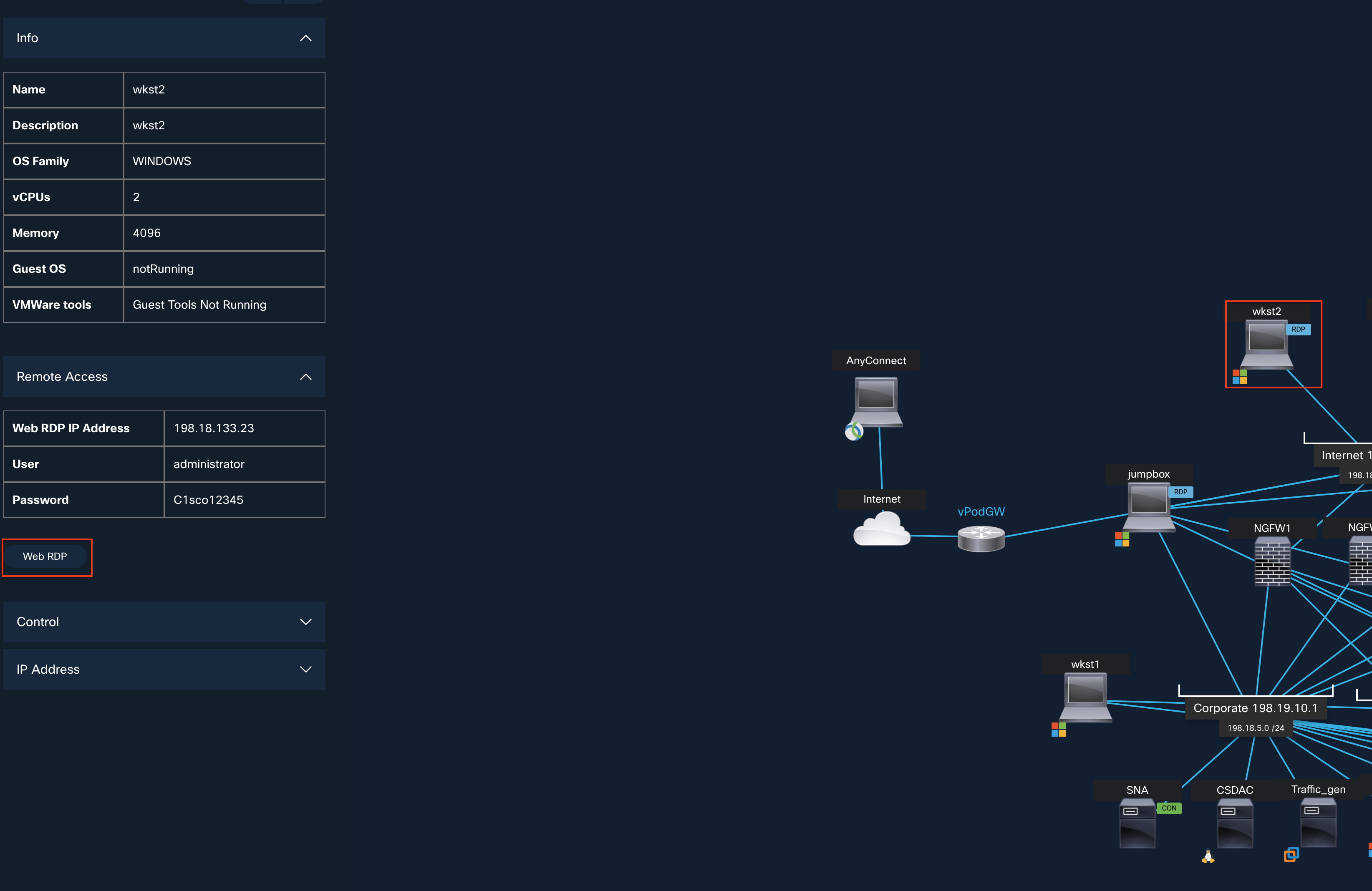
- First, we will test with a user whose connection will be routed based on the routes in the routing table (i.e. PBR will not be used).
- Open the AnyConnect client (Go to Windows > Cisco > Cisco AnyConnect Secure Mobility Client) and connect to NGFW1 (the profile and NGFW1 information is pre-populated)
- Use the following credentials:
- Username: engineeringuser
- Password: C1sco12345
Note
Since this is a lab environment, the Self-Signed Certificate is Enrolled for the RAVPN will show a warning message before making the connection. Click on Connect Anyway to proceed.
- Open the command prompt and ping 100.100.100.1
- Open the putty client (available on the desktop) and SSH to 100.100.100.1
- Note: We don't need to login to the router. Just the login prompt showing up is sufficient to capture the traffic in packet captures applied on the firewall.
- Use the following credentials:
- Return to the CLI of NGFW1.
- Use the
show routecommand to check the routing table. We will see the route for 100.100.100.0/24 through interface in10.
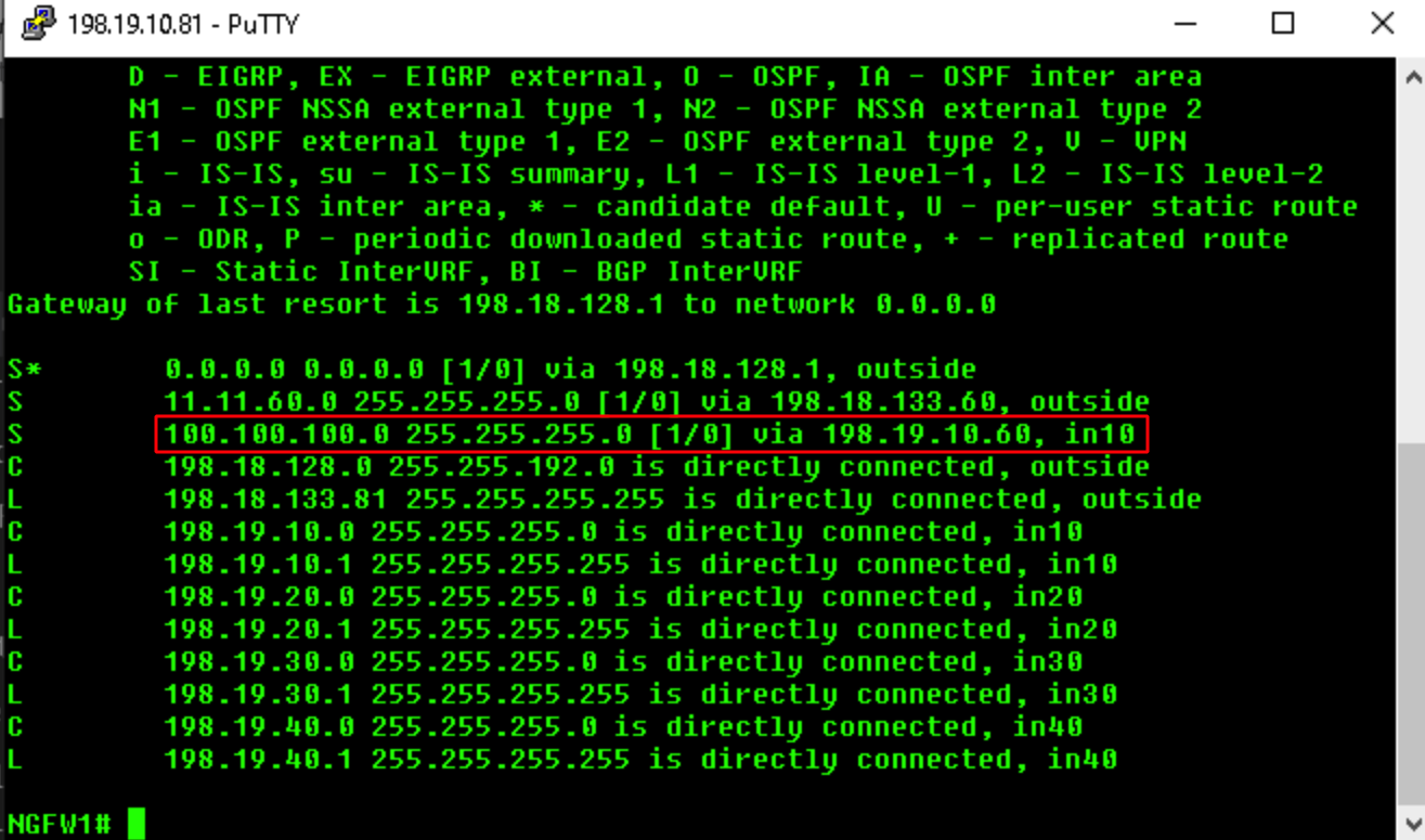
- Use the
show capturecommand to check the captures. We will see some packets/bytes in cap10, but no packets/bytes in cap20, showing that the packets used in10 interface as egress.
- Use the
show capture cap10command will show more details about the packets. We can see ICMP and SSH packets in the capture.
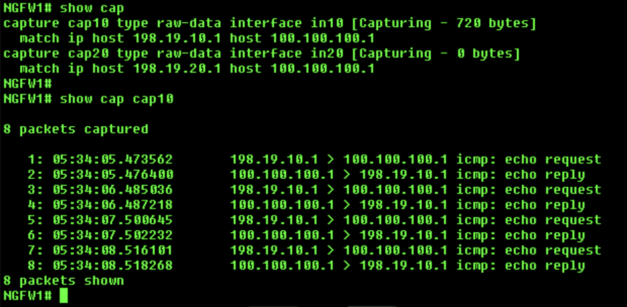
- Clear the captures using the
clear cap /allcommand. - Return to wkst2, disconnect the RAVPN session, and reconnect to NGFW1 using the following credentials:
- Username: networkadminuser
- Password: C1sco12345
- Open the command prompt and ping 100.100.100.1.
- Open the putty client (available on the desktop) and SSH to 100.100.100.1.
- Note: We don't need to login to the router. Just the login prompt showing up is sufficient to capture the traffic in packet captures applied on the firewall.
- Return to the CLI of NGFW1.
- Do a "show capture" to check the captures. This time we will see some packets/bytes in cap20, but no packets/bytes in cap10, showing that the PBR policy was applied to this connection and the packets were sent through in20 interface, even though the route in the routing shows in10 as the egress interface.
- Use the
show capture cap20command to show more details about the packets. We can see icmp and ssh packets in the capture.
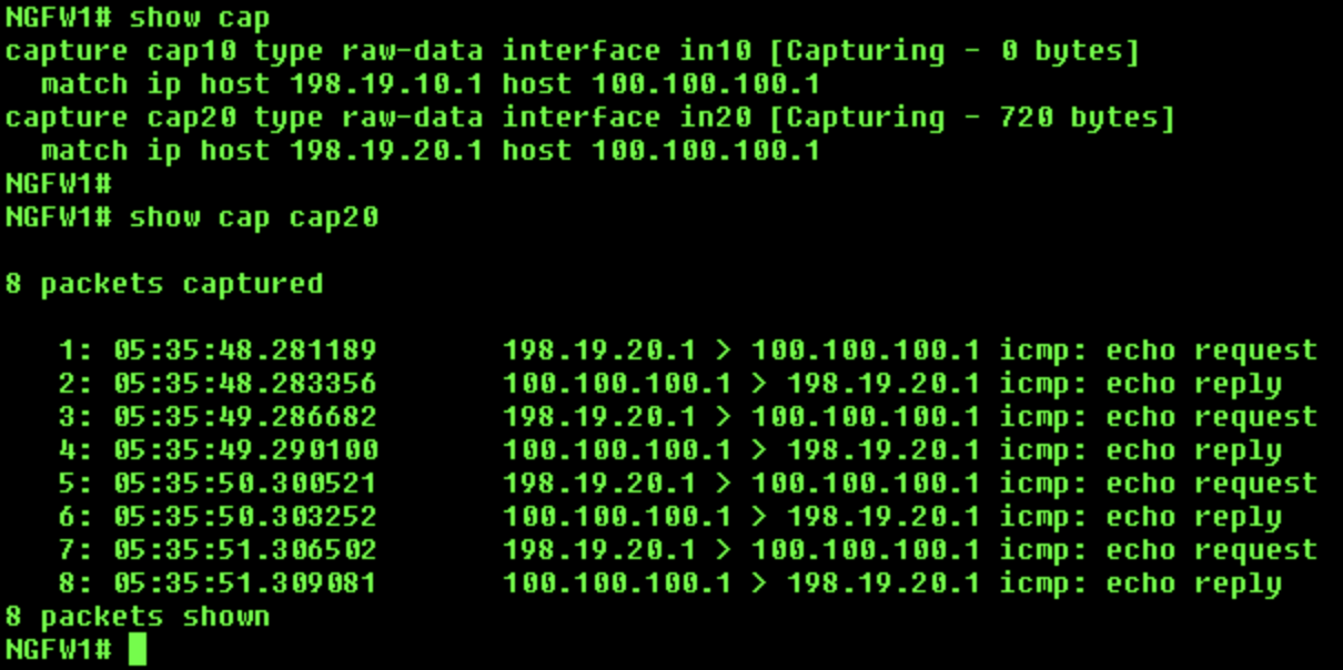
- Clear the captures using the
clear cap /allcommand.
Task 8 - Configure Policy Based Routing based on User Identity
- Now, we'll change the PBR policy to use the user's group information from the AD instead of SGT to route the packets.
- Go to Objects > Object Management > Access List > Extended and edit the PBR-ACL access list, then edit the entry created earlier:


- Go to the Security Group Tag tab and remove the SGT.
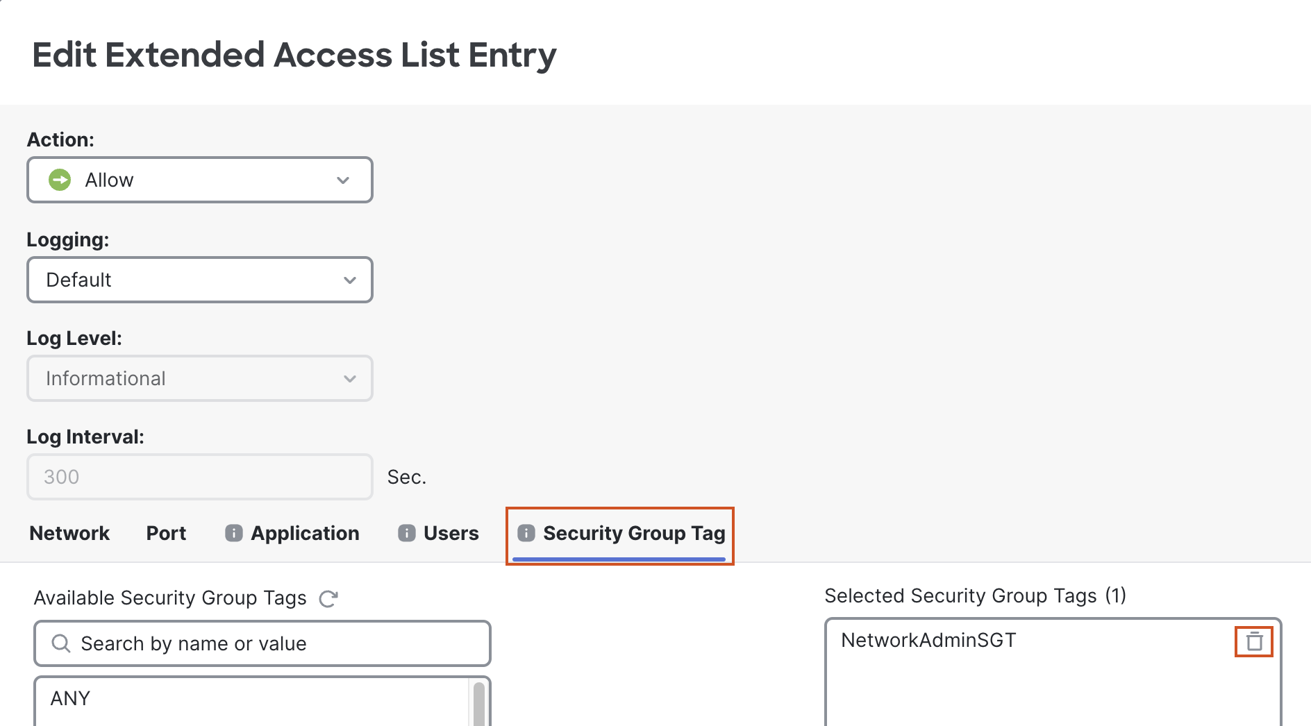
- Then go to the Users tab.
- In the Realm select dCloudRealm.
- Then in the Available Users box select NetworkAdminGroup.
- Click Save to save the updated entry.
- Click Save to save the changes to the ACL.
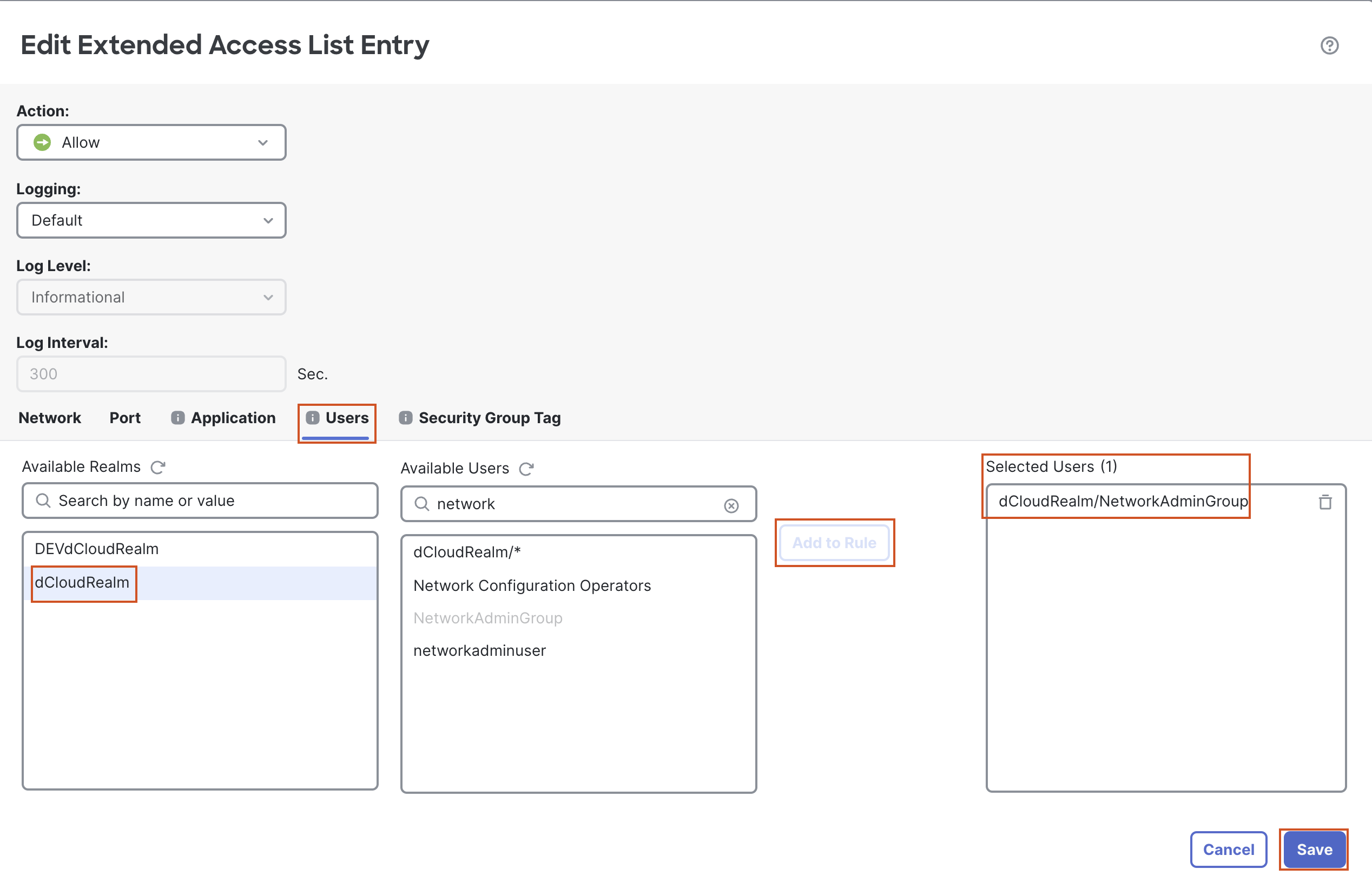
- Deploy the policy.
Task 9 - Verify Policy Based Routing
Note that this is essentially a repeat of the tests you did in Task 7. You should get the same results.
- Return to wkst2. You should still be logged into your RAVPN session as networkadminuser, so you should use PBR.
- Open the command prompt and ping 100.100.100.1.
- Open the putty client (available on the desktop) and SSH to 100.100.100.1.
- Note: We don't need to login to the router. Just the login prompt showing up is sufficient to capture the traffic in packet captures applied on the firewall.
- Return to the CLI of NGFW1
- Use the
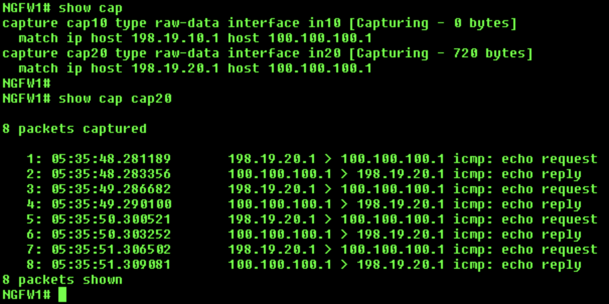
show capturecommand to check the captures. This time we will see some packets/bytes in cap20, but no packets/bytes in cap10, showing that the PBR policy was applied to this connection and the packets were sent through in20 interface, even though the route in the routing shows in10 as the egress interface.
- The
show capture cap20command will show more details about the packets. We can see ICMP and SSH packets in the capture.
-
Clear the captures using the
clear cap /allcommand. -
Now we will test with a user whose connection will be routed based on the routes in the routing table (i.e. PBR will not be used).
-
Go back to wkst2 disconnect your RAVPN session and reconnect using the following credentials:
- Username: engineeringuser
- Password: C1sco12345
- Open the command prompt and ping 100.100.100.1.
- Open the putty client (available on the desktop) and SSH to 100.100.100.1.
- Note: We don't need to login to the router. Just the login prompt showing up is sufficient to capture the traffic in packet captures applied on the firewall.
- Return to the CLI of NGFW1
- Use the
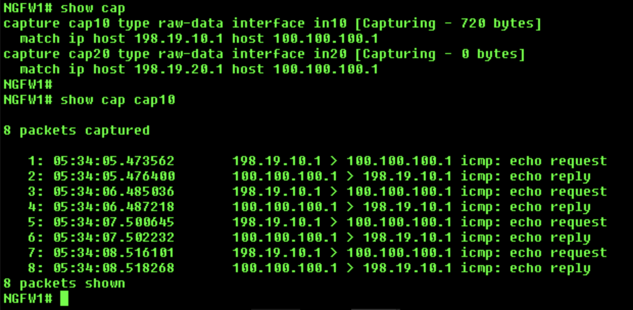
show capturecommand to check the captures. We will see some packets/bytes in cap10, but no packets/bytes in cap20, showing that the packets used in10 interface as egress. - Use the
show capture cap10command to show more details about the packets. We can see ICMP and SSH packets in the capture.
- Clear the captures using the
clear cap /allcommand.
Success
This concludes the lab for PBR with SGT and User Identity.
Updated 7 months ago
