
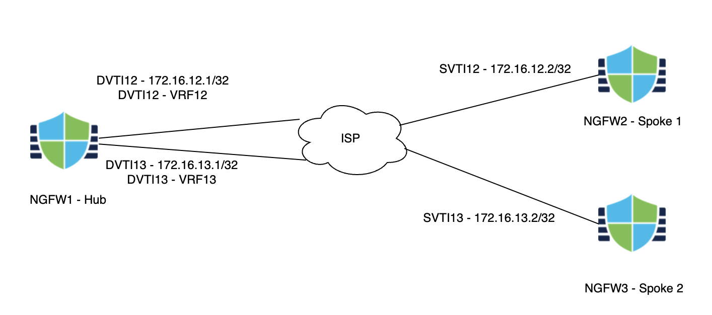
Scenario 6 - VRF Support for DVTI
Virtual Route Forwarding (VRF) enables customers to separate out routing and forwarding domains for ease of operations. VRFs were first introduced in version 6.6. In version 7.2, we introduced Dynamic Virtual Tunnel Interfaces for ease of building VPN tunnels. In this version, we add the ability to associate a DVTI with a VRF to help with network segmentation.
Lab Tasks
These are the tasks in the scenario below. If you are familiar with the Secure Firewall you may do these on your own, or for step-by-step instructions see below.
- Task 1 - Configure DVTIs on NGFW1
- Task 2 - Configure VRFs on NGFW1
- Task 3 - Configure SVTI on NGFW2
- Task 4 - Configure SVTI on NGFW3
- Task 5 - Configure VPN Topologies
- Task 6 - Verification
Task 1 - Configure DVTIs on NGFW1
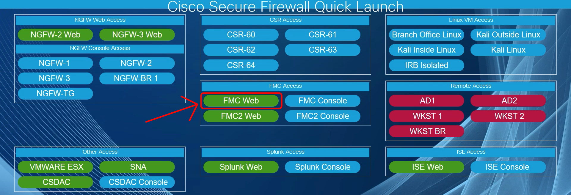
- Using the Quick Launch or the Google Chrome browser connect to the FMC web UI.
Login as admin/C1sco12345. These credentials should be pre-populated in the browser.
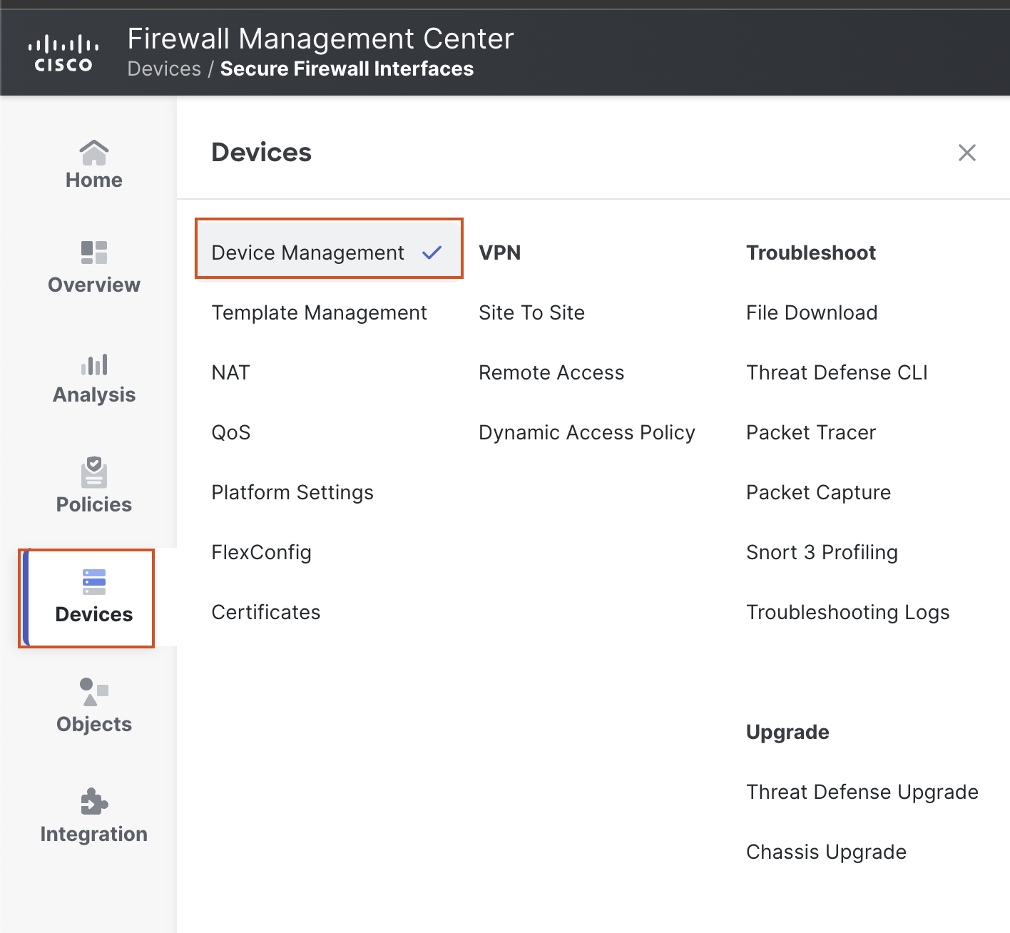
- Go to Device > Device Management and click the pencil (edit) icon next to NGFW1.
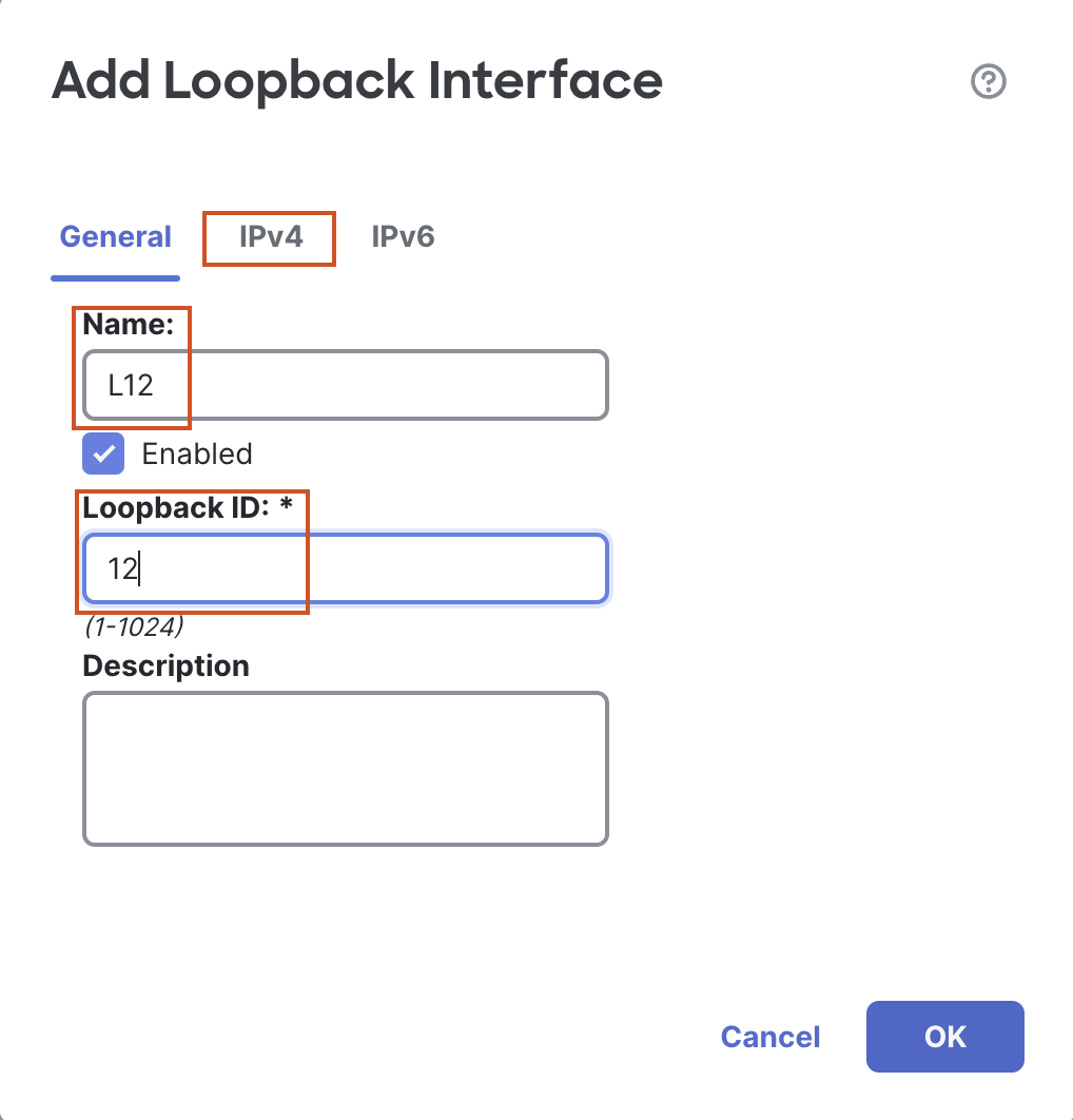
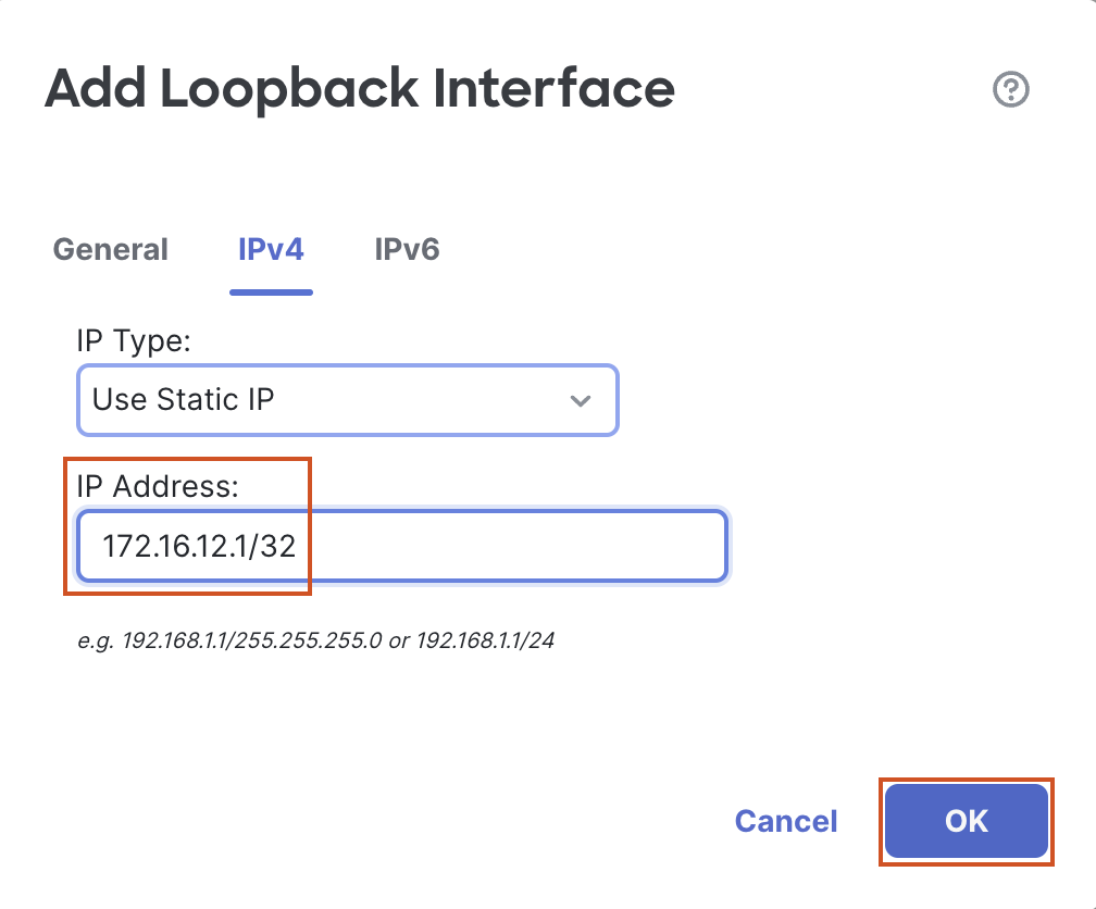
- Click on Add Interfaces > Loopback Interface to add a new loopback interface.
- In the pop up box, configure the following details:
- In the General Tab
- Name: L12
- Loopback ID: 12
- In the IPv4 Tab
- IP Address: 172.16.12.1/32
- In the General Tab
- Click on OK to save the interface.
- In the pop up box, configure the following details:
- Click on Add Interfaces > Loopback Interface to add another loopback interface.
- In the pop up box, configure the following details:
- In the General Tab
- Name: L13
- Loopback ID: 13
- In the IPv4 Tab
- IP Address: 172.16.13.1/32
- In the General Tab
- Click on OK to save the interface.

- In the pop up box, configure the following details:
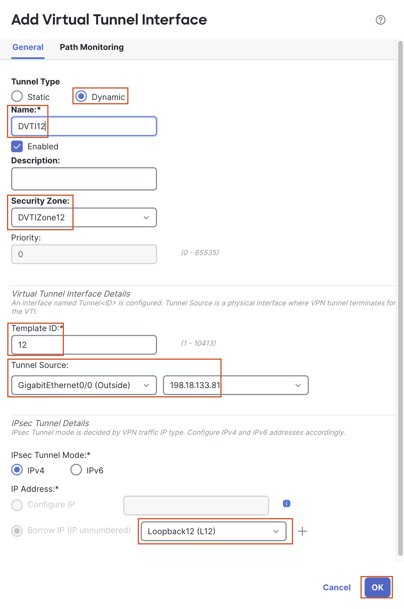
- Click on Add Interfaces > Virtual Tunnel Interface to add a VTI.
- In the pop up box, configure the following details:
- Tunnel Type: Dynamic
- Name: DVTI12
- Security Zone: In the drop-down, click New...
- Add a new zone named "DVTIZone12" and click OK.
- Template ID: 12
- Tunnel Source: GigabitEthernet0/0 (outside)
- Tunnel Source Address: 198.18.133.81 (outside interface IP address, available in the drop down once the tunnel source is selected)
- IP Address: Borrow IP (IP unnumbered) will be selected by default. From the drop down next to it, select Loopback12 (L12)
- Click on OK to save the DVTI.
- In the pop up box, configure the following details:
Note
For a DVTI, we cannot configure an IP address, a DVTI must borrow an IP address from an interface. Hence, "Borrow IP" option is selected by default and greyed out, since we cannot change this option.
- Click on Add Interfaces > Virtual Tunnel Interface to add another VTI.
- In the pop up box, configure the following details:
- Tunnel Type: Dynamic
- Name: DVTI13
- Security Zone: In the drop-down, click New...
- Add a new zone named "DVTIZone13" and click OK.
- Template ID: 13
- Tunnel Source: GigabitEthernet0/0 (outside)
- Tunnel Source Address: 198.18.133.81 (outside interface IP address, available in the drop down once the tunnel source is selected)
- IP Address: Borrow IP (IP unnumbered) will be selected by default. From the drop down next to it, select Loopback13 (L13)
- Click OK to save the DVTI.
- In the pop up box, configure the following details:
- Click Save to save the changes

Task 2 - Configure VRFs on NGFW1
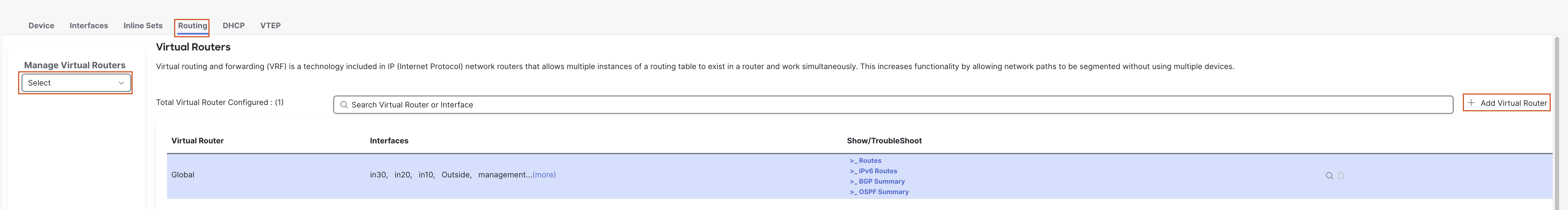
- You should still be editing the device NGFW1 (otherwise, go to Device > Device Management and click the pencil (edit) icon next to NGFW1). Go to the Routing tab.
- In the left bar, click on Manage Virtual Routers.
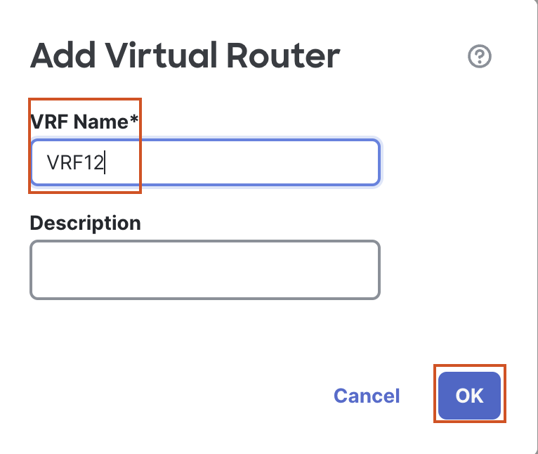
- Click on + Add Virtual Router to add a VRF.
- In the pop up box, enter the Name "VRF12".
- Click on OK to save the new VRF.
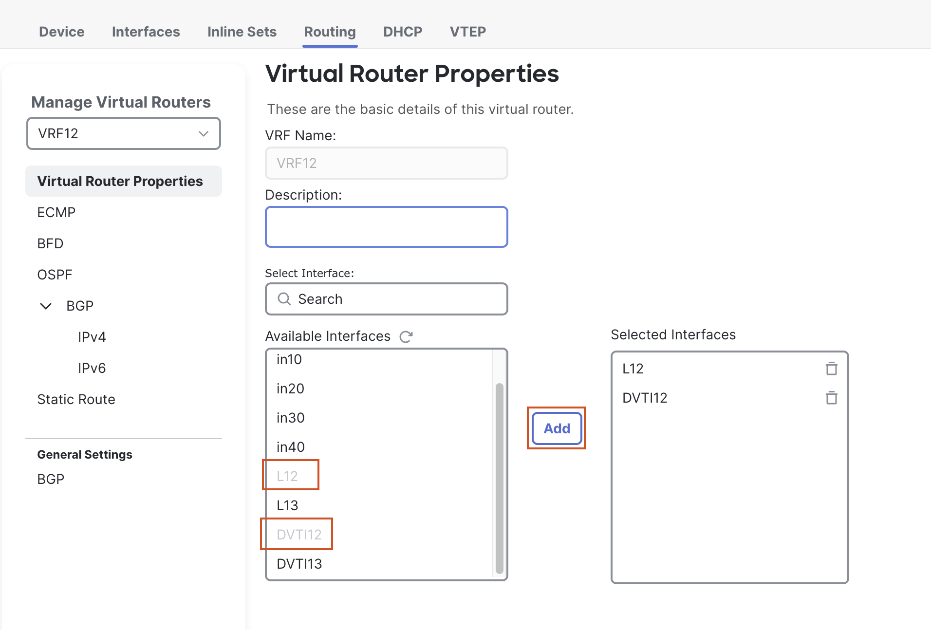
- A new page will open up to configure Virtual Router Properties.
- From the Available Interfaces section, select L12 and click on Add to move it to the Selected Interfaces section.
- Then select DVTI12, and click on Add to move it to the Selected Interfaces section.
- Click on + Add Virtual Router to add a VRF.
- In the left bar, click on Manage Virtual Routers again.
- Click on + Add Virtual Router to add another VRF.
- In the pop up box, enter the Name "VRF13".
- Click on OK to save the new VRF.
- A new page will open up to configure Virtual Router Properties.
- From the Available Interfaces section, select L13 and click on Add to move it to the Selected Interfaces section.
- Then select DVTI13, and click on Add to move it to the Selected Interfaces section.
- Click on + Add Virtual Router to add another VRF.
- Click on Save to save the changes.
Task 3 - Configure SVTI on NGFW2
- Go to Device > Device Management and click the pencil (edit) icon next to NGFW2.
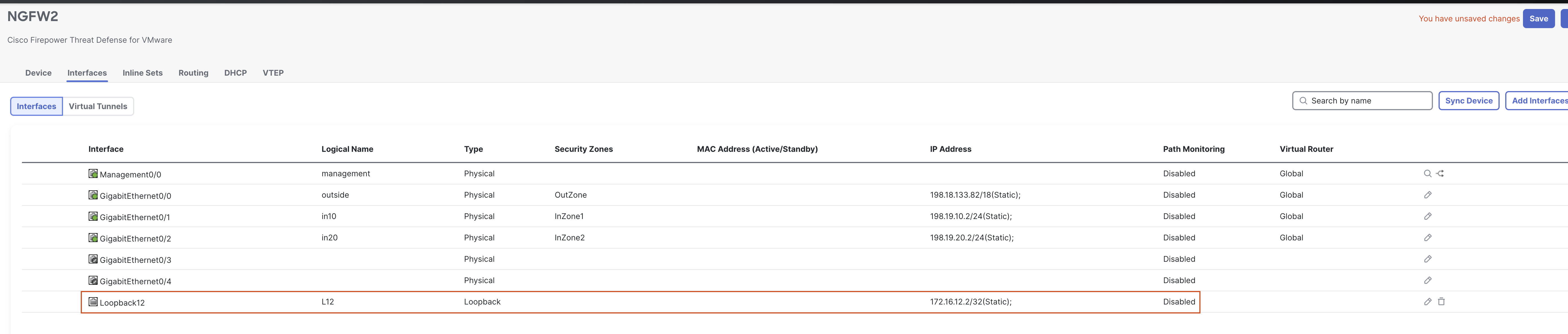
- Click on Add Interfaces > Loopback Interface to add a new loopback interface.
- In the pop up box, configure the following details:
- In the General Tab
- Name: L12
- Loopback ID: 12
- In the IPv4 Tab
- IP Address: 172.16.12.2/32
- In the General Tab
- Click on OK to save the interface.
- In the pop up box, configure the following details:
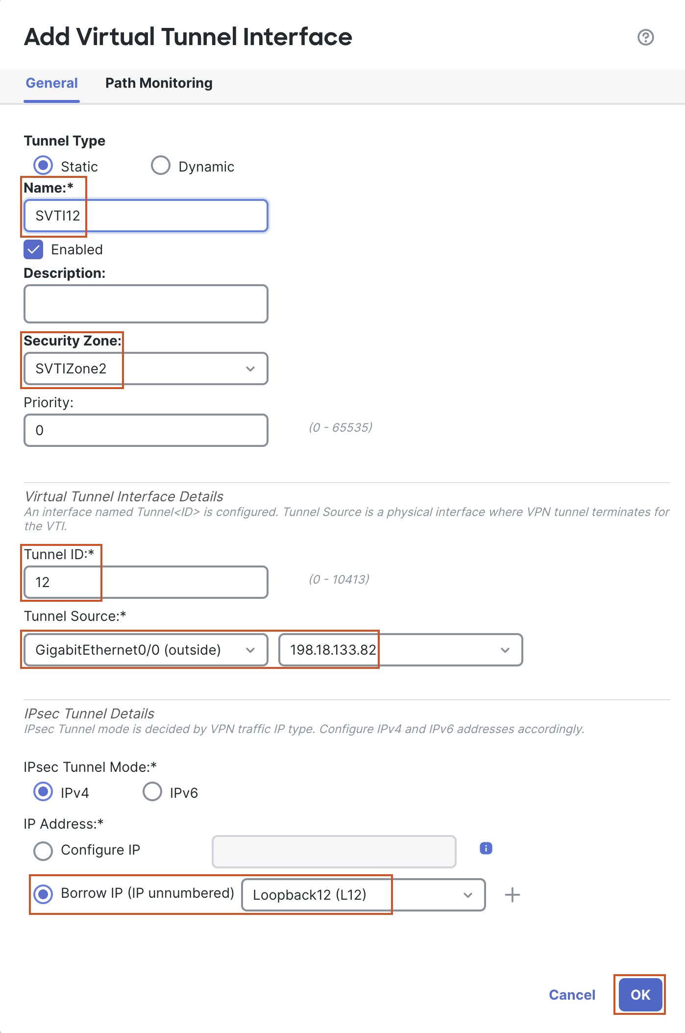
- Click on Add Interfaces > Virtual Tunnel Interface to add a VTI.
- In the pop-up box, configure the following details:
- Tunnel Type: Static
- Name: SVTI12
- Security Zone: In the drop-down, click New... .
- Add a new zone named "SVTIZone12" and click OK.
- Tunnel ID: 12
- Tunnel Source: GigabitEthernet0/0 (outside)
- Tunnel Source Address: 198.18.133.82 (outside interface IP address, available in the drop-down once the tunnel source is selected)
- IP Address: Click the radio button for Borrow IP (IP unnumbered) and from the drop-down list next to it, select Loopback12 (L12).
- Click OK to save the VTI .
- In the pop-up box, configure the following details:
- Click Save to save the changes
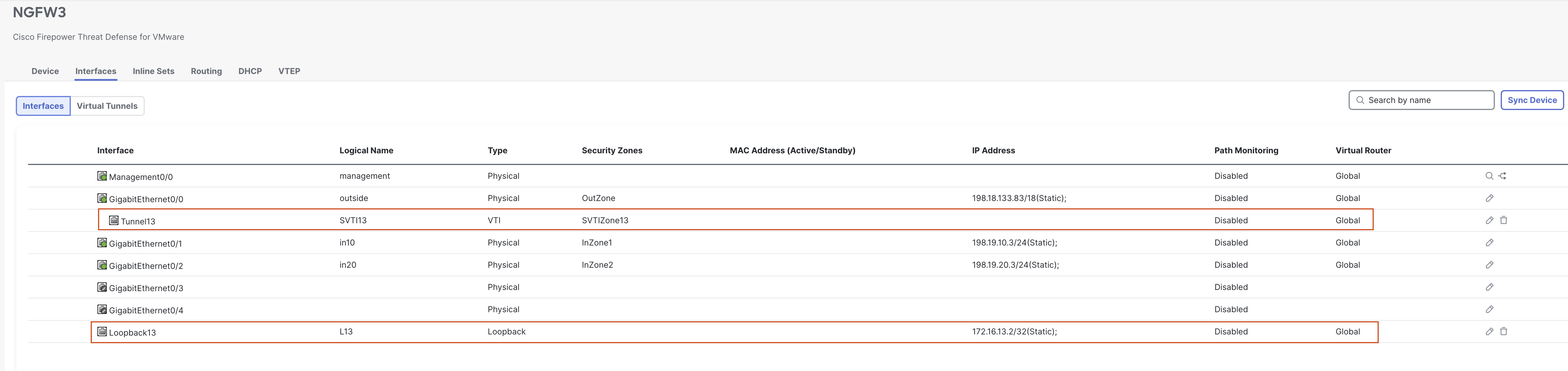
Task 4 - Configure SVTI on NGFW3
- Go to Device > Device Management and click the pencil (edit) icon next to NGFW3.
- Click on Add Interfaces > Loopback Interface to add a new loopback interface.
- In the pop-up box, configure the following details:
- In the General Tab
- Name: L13
- Loopback ID: 13
- In the IPv4 Tab
- IP Address: 172.16.13.2/32
- In the General Tab
- Click on OK to save the interface.
- In the pop-up box, configure the following details:
- Click on Add Interfaces > Virtual Tunnel Interface to add a VTI.
- In the pop-up box, configure the following details:
- Tunnel Type: Static
- Name: SVTI13
- Security Zone: In the drop-down, click New....
- Add a new zone named "SVTIZone13" and click OK.
- Tunnel ID: 13
- Tunnel Source: GigabitEthernet0/0 (outside)
- Tunnel Source Address: 198.18.133.83 (outside interface IP address, available in the drop-down once the tunnel source is selected)
- IP Address: Borrow IP (IP unnumbered) will be selected by default. From the drop-down next to it, select Loopback13 (L13).
- Click OK to save the VTI.
- In the pop-up box, configure the following details:
- Click on Save to save the changes.
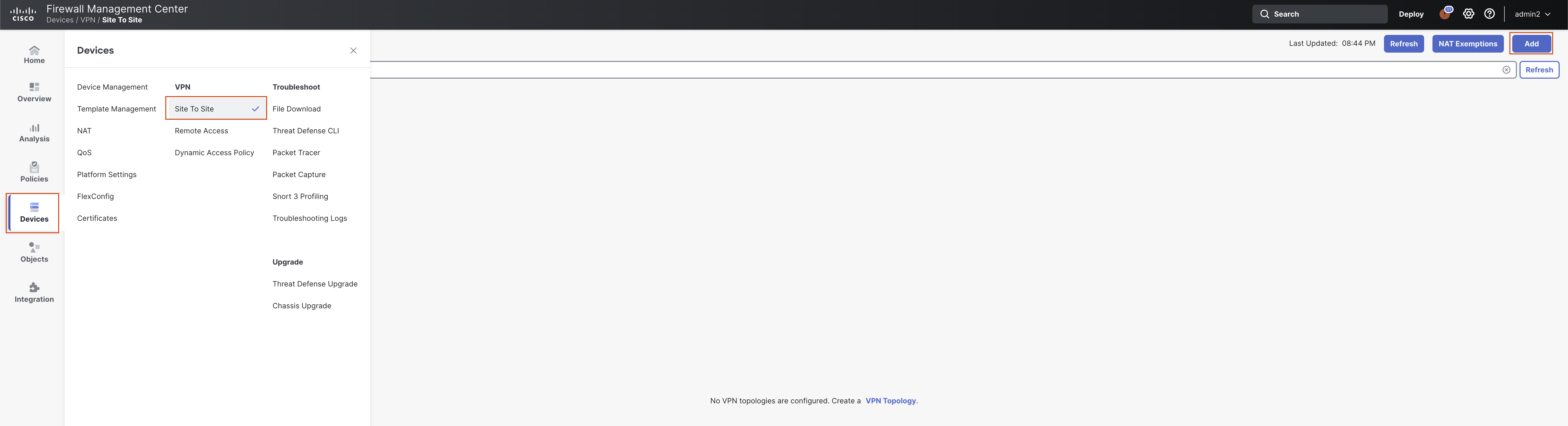
Task 5 - Configure VPN Topologies
-
Go to Devices > VPN > Site to Site and click on + Site to Site VPN.
-
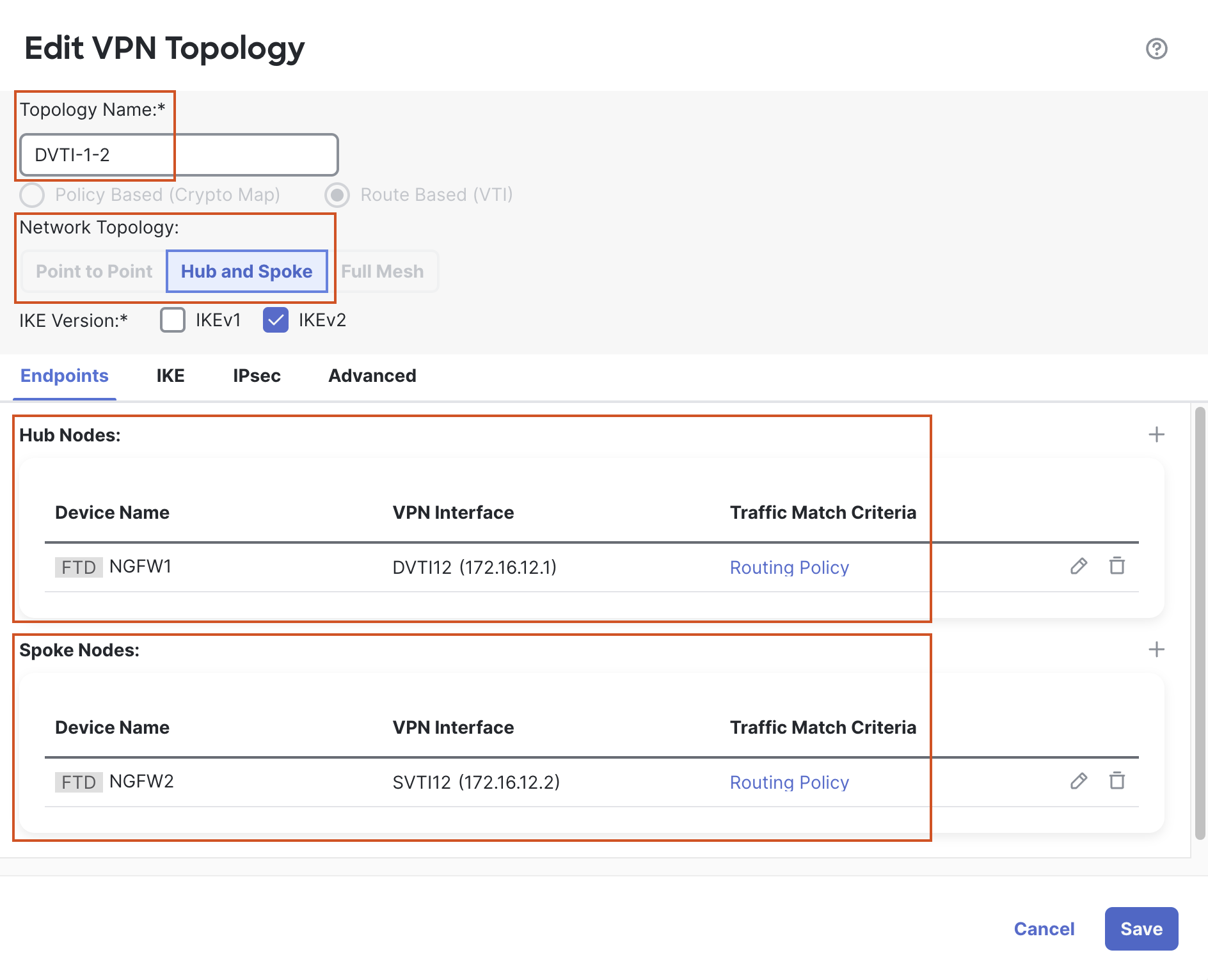
In the pop-up box, configure the following details:
-
Topology Name: DVTI-1-2
-
Select the Radio Button for "SD-WAN Topology".
-
Select VPN Topology: Hub and Spoke
-
Click on + next to Hub Nodes.
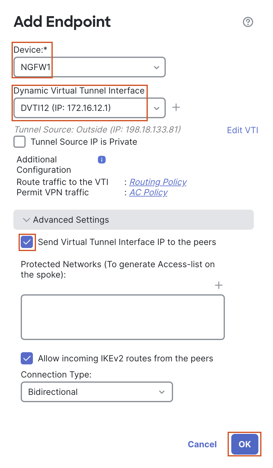
- In the pop-up box, configure the following details:
- Device: NGFW1
- Dynamic Virtual Tunnel Interface: DVTI12
- In the Advanced Settings, check the box "Send Virtual Tunnel Interface IP to the peers".
- Leave all other settings as default and click on OK.
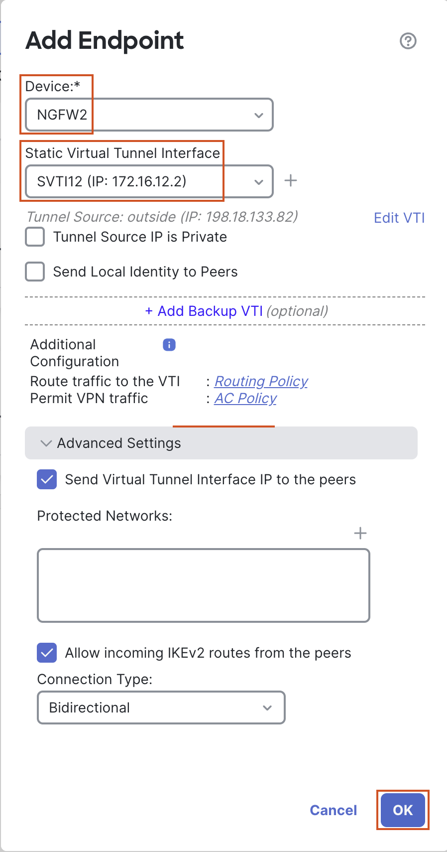
- In the pop-up box, configure the following details:
-
Click on + next to Spoke Nodes.
- In the pop up box, configure the following details:
- Device: NGFW2
- Statis Virtual Tunnel Interface: SVTI12
- In the Advanced Settings, make sure the box "Send Virtual Tunnel Interface IP to the peers" is checked (it is checked by default).
- Leave all other settings as default and click OK
- In the pop up box, configure the following details:
-
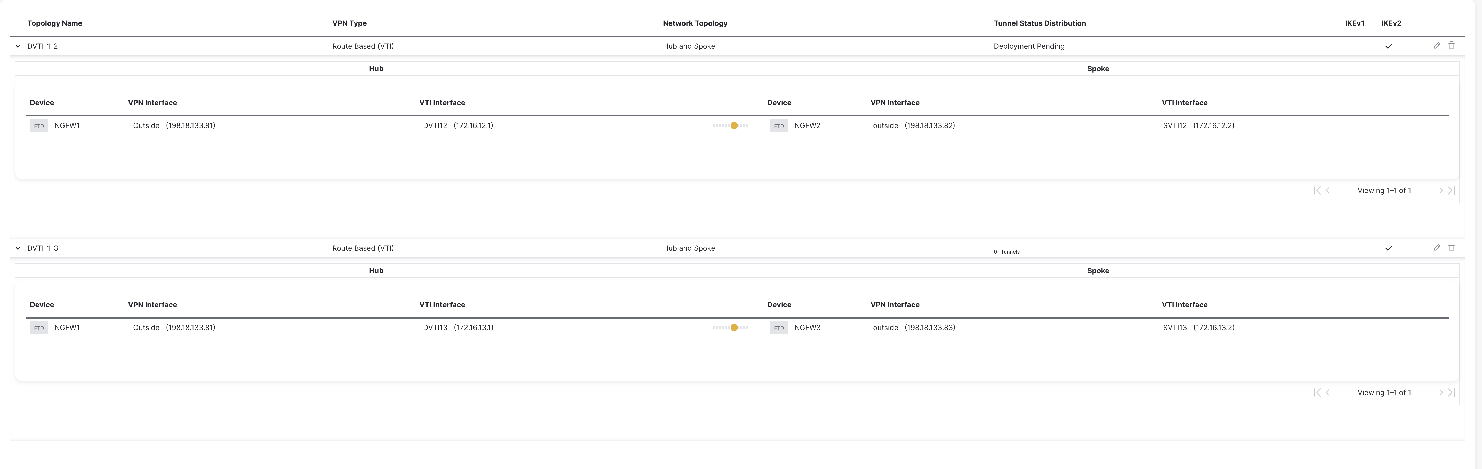
Click Save to save the Topology.
-
-
-
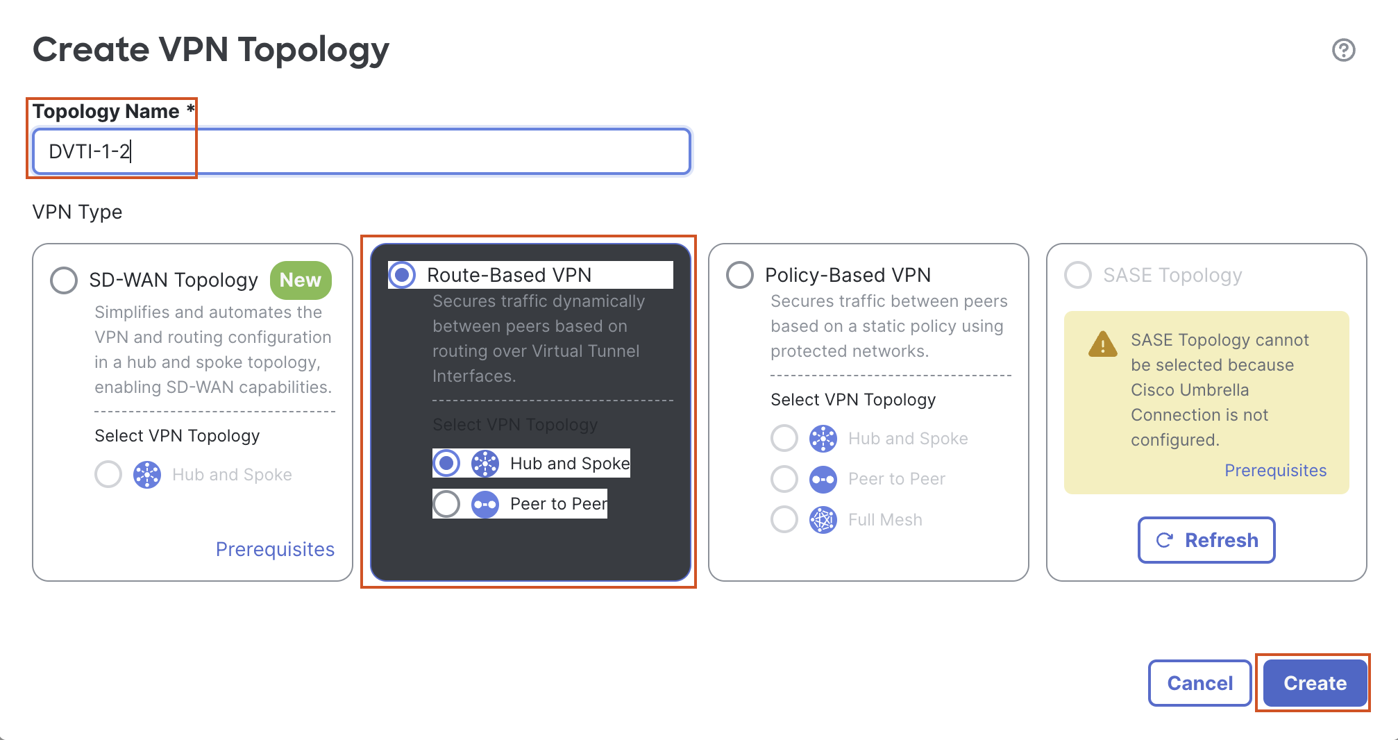
Click on + Site to Site VPN again, to add another VPN topology.
-
In the pop up box, configure the following details:
-
Topology Name: DVTI-1-3
-
Select the Radio Button for "Route Based (VTI)"
-
Network Topology: Hub and Spoke
-
Click on + next to Hub Nodes
- In the pop up box, configure the following details:
- Device: NGFW1
- Dynamic Virtual Tunnel Interface: DVTI13
- In the Advanced Settings, check the box "Send Virtual Tunnel Interface IP to the peers".
- Leave all other settings as default and click on OK.
- In the pop up box, configure the following details:
-
Click on + next to Spoke Nodes..
- In the pop up box, configure the following details:
- Device: NGFW3
- Statis Virtual Tunnel Interface: SVTI13
- In the Advanced Settings, make sure the box "Send Virtual Tunnel Interface IP to the peers" is checked (it is checked by default).
- Leave all other settings as default and click on OK.
- In the pop up box, configure the following details:
-
Click on Save to save the Topology.
-
-
-
Click on Deploy to deploy the changes to all three firewalls.
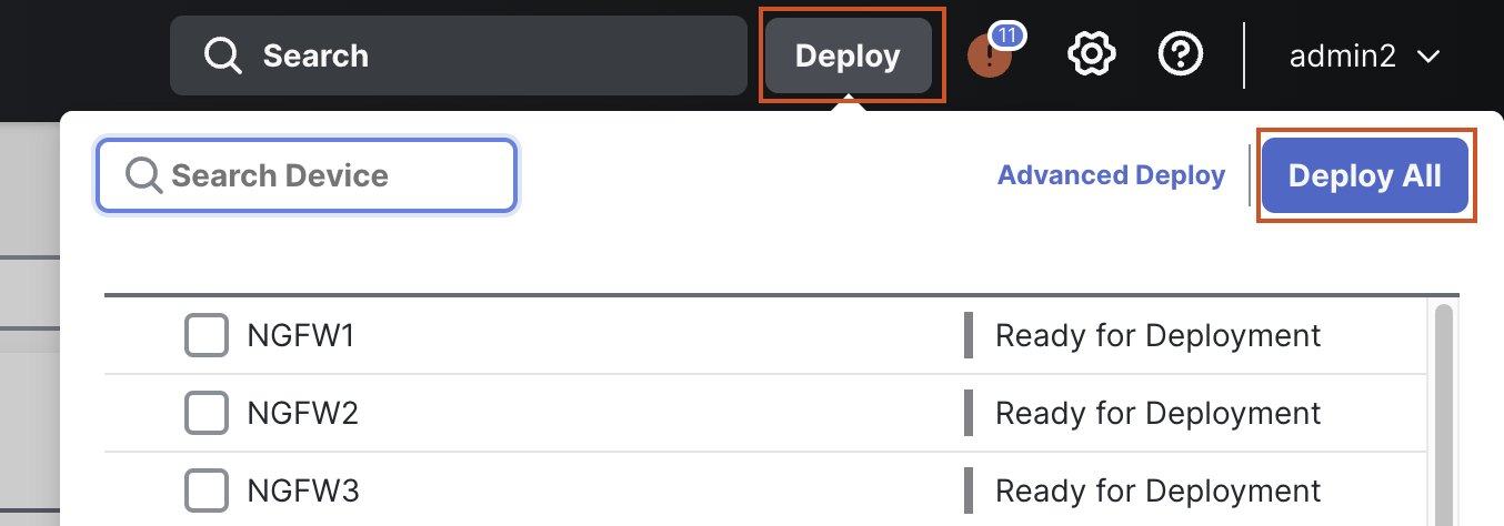
Note
You will get a warning "The changes to Virtual Routers may cause traffic disruption." This is expected as we have configured new VRFs. Click on the "Ignore Warnings" checkbox and click on Deploy to deploy the changes.
Task 6 - Verification
-
Connect to the CLI of NGFW1. The credentials will be pre-populated.
-
Connect to the diagnostic cli by using the
system support diagnostic-clicommand.- Use the
enablecommand to log into enable mode (privileged mode) and leave the password as blank.
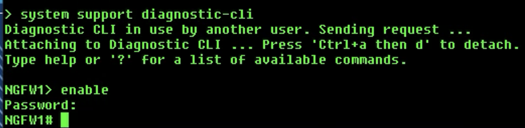
- Use the
-
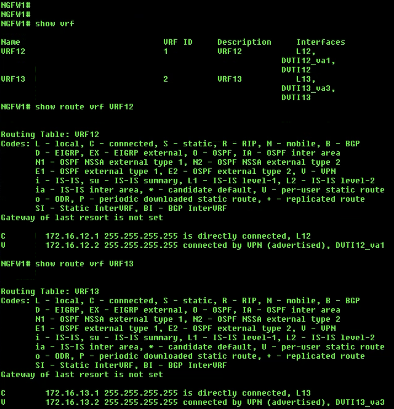
Use the
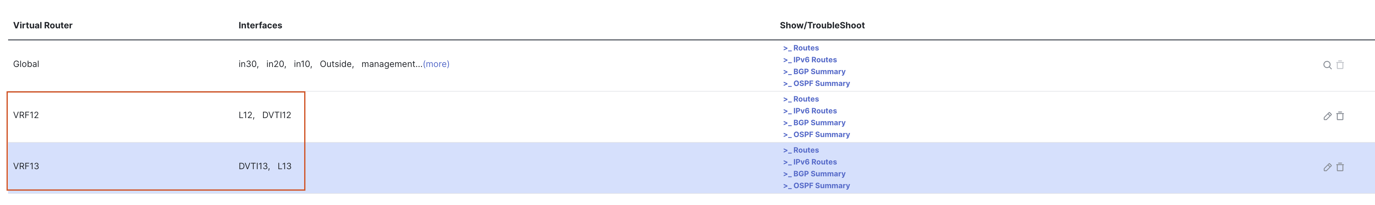
show vrfcommand to see the configured VRFs and the interfaces associated with them. -
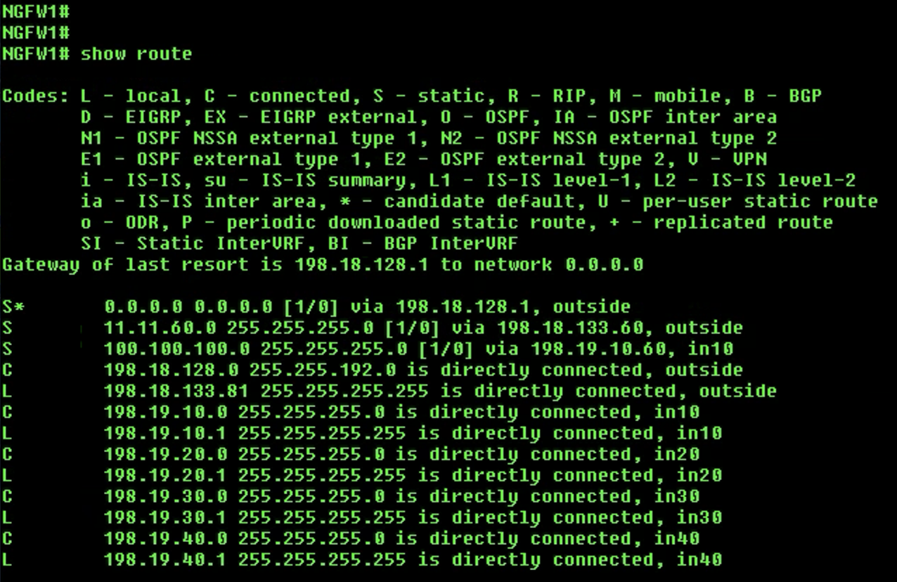
Use the
show routecommand to check the routes in the global routing table. We will not see the two loopback and DVTI interfaces in the routing table. -
Use the
show route vrf <vrf name>command to check the routes for both VRFs. We will see the routes for respective loopback and DVTI interfaces.
-
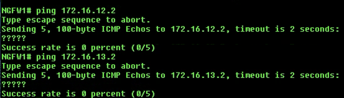
Check connectivity using the following
pingcommands:-
Global Router:
ping 172.16.12.2- This ping will failping 172.16.13.2- This ping will also fail
-
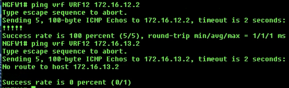
VRF12:
ping vrf VRF12 172.16.12.2- This ping will succeedping vrf VRF12 172.16.13.2- This ping will fail
-
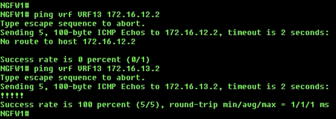
VRF13:
ping vrf VRF13 172.16.12.2- This ping will failping vrf VRF13 172.16.13.2- This ping will succeed
-
Success
This concludes the lab for VRF Support for DVTI.