
Secure Firewall Reference Architecture for Individual Interface Mode Clusters
This document provides a comprehensive reference architecture of Cisco Secure Firewall Clustering individual interface mode clustering deployments, including inter-site clustering. It details the design principles, configuration specifics, and operational aspects of building a highly resilient and redundant firewall cluster spanning single or multiple geographical locations. Through a series of simulated failure scenarios—including individual node failures, interface failures, and complete site outages—this guide demonstrates the cluster's ability to maintain stateful connections and ensure continuous traffic flow, displaying the robust high availability and disaster recovery capabilities inherent in this architecture.
This guide is primarily intended for network architects, security engineers, and technical consultants responsible for designing, implementing, and validating advanced, highly available security infrastructures using Cisco Secure Firewall. It assumes a foundational understanding of networking concepts, Cisco Secure Firewall operations, and routing protocols.
Clustering Basics
Cisco Firewall Clustering combines multiple firewalls into a single logical unit. The connected routers and/or switches see the whole cluster as one unit, not as individual firewalls. The cluster is built to have increased throughput and redundancy with stateful failover. The total throughput of a cluster is 80% of the aggregated throughput of the individual nodes. The remaining 20% goes into CPU and memory overhead involved in the creation and maintenance of flows, as well as for Cluster Control Link traffic. It is recommended to have N+1 firewalls deployed in a cluster if the required throughput is obtained from N firewall units. Therefore, in the event of a failure of one of the firewalls, the throughput of the cluster is not impacted. A cluster has one Control Node, and the rest of the nodes are Data Nodes. All nodes process transit connections; no node in a cluster is in standby mode.
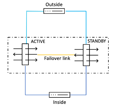
Cluster vs. High Availability
Cluster:
High Availability:
| Feature | High Availability | Clustering |
|---|---|---|
| Operational Mode | Active/Standby: One device processes all traffic; the other is idle, ready to take over. | Active/Active: All devices in the cluster actively process traffic concurrently. |
| Resource Utilization | 50% efficiency: Standby unit's resources are unused during normal operation. | High efficiency: All nodes contribute to traffic processing, maximizing hardware utilization. |
| Scalability | Limited: Typically involves only two devices (Active and Standby). | Highly Scalable: Can scale up to 16 units without traffic disruption. |
| Throughput | Limited to the maximum throughput of a single active device. | Aggregated Throughput: Sum of throughputs of all active nodes (minus some overhead, approx. 80% of aggregated). |
| Complexity | Relatively simpler to configure and manage. | More complex to design, configure, and troubleshoot, especially with inter-site deployments and external load balancing. |
| Inter-site Support | Possible, but often requires more complex routing/network design to manage failover across sites. | Designed for Inter-site: Supports extending the cluster across multiple geographical locations. |
| Load Balancing | Not applicable in active/standby. | Built-in or External: Can use proprietary hash algorithms (Spanned Mode) or external mechanisms like PBR, ECMP, or ITD (Individual Mode). |
| Dedicated Links | Requires a dedicated failover link (and state link) between the two devices. | Requires a Cluster Control Link (CCL) for intra-cluster communication, state replication, and control node election. |
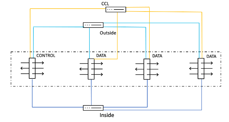
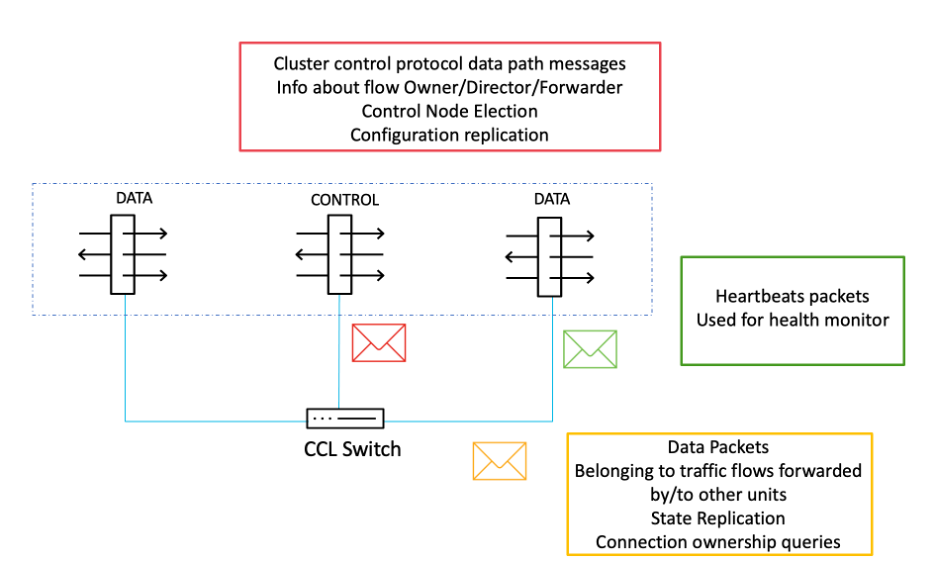
Cluster Control Link (CCL)
CCL link is an isolated, high-speed backplane network for intra-cluster communication. A dedicated interface from each unit in a cluster is connected to a switch to form the Cluster Control Link, which carries control and data traffic. Each Cluster Control Link has an IP address on the same subnet. This subnet should be isolated from all other traffic and should include only the Cluster Control Link interfaces. CCL carries control traffic, which includes configuration replication, control node election, etc., heartbeat packets, and data traffic from other nodes to the owners of the traffic flow. A connection is owned by the owner, and if packets belonging to the connection are delivered to a node other than the owner, they are forwarded to the owner via the CCL.
It is recommended to have the CCL MTU at least 100 bytes more than the data interface MTU, as the CCL overhead is 100 bytes. In case of Virtual clusters, the CCL MTU must be at least 154 bytes more than the data interface MTU, with the additional 54 bytes being the VXLAN overhead.
Clustering works with both Cisco and non-Cisco switches from other major switching vendors with no known interoperability issues, provided they comply with the following requirements and recommendations. Clustering is compatible with technologies such as vPC (Nexus), VSS (Catalyst), and StackWise & StackWise Virtual (Catalyst).
Switch Requirements
• All third-party switches must be compliant with the IEEE standard (802.3ad) Link Aggregation Control Protocol.
• EtherChannel bundling must be completed within 45 seconds when connected to Firepower devices
• On the Cluster Control Link, the switch must provide fully unimpeded unicast and broadcast connectivity at Layer 2 between all cluster members.
• On the Cluster Control Link, the switch must not impose any limitations on IP addressing or the packet format above Layer 2 headers.
• On the Cluster Control Link, the switch interfaces must support jumbo frames and be configurable for an MTU above 1600.
Switch Recommendations
• The switch should provide uniform traffic distribution over the EtherChannel's individual links.
• The switch should have an EtherChannel load-balancing algorithm that provides traffic symmetry.
• The EtherChannel load-balance hash algorithm should be configurable using the 5-tuple, 4-tuple, or 2-tuple to calculate the hash.
Connection Roles
The following main roles are defined for each connection through a firewall cluster:
- Owner - The node that initially receives the connection. A connection has only one owner.
- Backup Owner - The node that stores TCP/UDP state information received from the owner, so that the connection can be seamlessly transferred to a new owner in case of a failure.
- Director - The node that handles owner lookup requests from forwarders.
- Forwarder - A node that forwards packets to the owner.
Cluster Modes
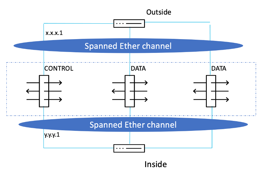
A firewall cluster can be deployed in two modes – Individual Interface and Spanned EtherChannel modes, which work on Layer 3 and Layer 2, respectively.
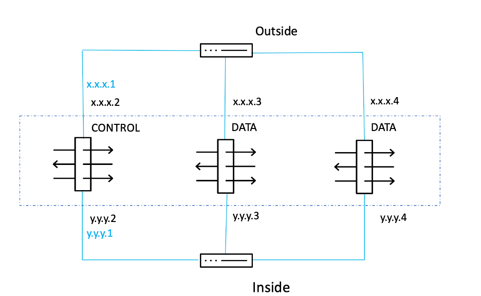
In Individual Interface mode, each unit has its own interface IP address obtained from the cluster pool, which is a range of IP addresses. A main cluster IP address also exists, which is fixed and always belongs to the control node. The load balancing of traffic must be done by the connected routers/switches, either by Policy-Based Routing (PBR), Equal-Cost Multi-path(ECMP), or Intelligent Traffic Director (ITD). ECMP load balancing can be done either via static routing or via dynamic routing protocols. Dynamic routing protocols are recommended since the routes get updated automatically in case of node failure.
In the figure below, x.x.x.1 and y.y.y.1 are the main cluster IP addresses.
Whereas, in a Spanned mode, the corresponding interfaces from the units are bundled into an EtherChannel, and here the load balancing of traffic is done by the proprietary hash algorithm of the EtherChannel based on source or destination IP addresses and TCP and UDP port numbers. Spanned mode is not supported in virtual FTD since layer 2 semantics are not supported in public clouds, and EtherChannel is not supported in private clouds.
| Individual Interface mode | Spanned EtherChannel Mode |
|---|---|
| Works on Layer 3 | Works on Layer 2 |
| Load balancing via PBR or ECMP or ITD | Load balancing via EtherChannel |
| Only routed firewall mode supported | Both transparent and routed firewall modes supported |
| Supported Models: vFTD, 3100, 4200 | Supported Models: 3100, 4200, 4100, 9300 |
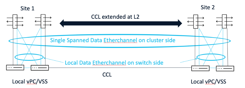
Inter-Site Cluster
A cluster extending across two or more geographical locations (i.e. sites) is called an inter-site cluster. Configuration here is done by specifying the site ID for the cluster nodes.
In the case of Spanned mode, the CCL link is extended at Layer 2 across the sites, and the data interfaces are configured in split-spanned EtherChannel interface mode, wherein the EtherChannel is local on the switch side but spanned on the firewall cluster side.
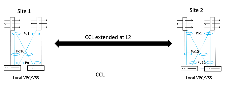
In the case of Individual Interface mode, the CCL is again extended at Layer 2, but the data interfaces are configured with their own IP addresses. In the example below, Port-Channel 1 (Po1) is on the firewall side and Port-Channels 10 and 11 (Po10 and Po11) are on the switch side.
Cluster Benefits
- Active/Active - Cisco Secure Firewall supports active/active clustering, which allows all firewall nodes to perform security enforcement duties concurrently, optimizing resource utilization.
- Seamless Scalability - Secure Firewall clustering can scale up to 16 units without traffic disruption, providing stateful handling of asymmetric traffic and failure recovery.
- Single Point of Management - Secure Firewall offers unified reporting and management, and simplifies operations by managing the full cluster as a single device with a single unified policy.
- Connection State Replication - The Cluster Control Link (CCL) facilitates state replication and connection ownership queries, ensuring that connection states are preserved and seamlessly transferred to other nodes in the event of Control Node failure.
Reference Topology
In this example, we have two sites, SITE 1 and SITE 2, with firewalls, routers, and switches in each site. A four-node cluster is built with two nodes in each site.
Components
The firewalls (hardware model FPR4245) are in routed mode, and the cluster mode used here is Individual Interface mode.
a. Firewalls
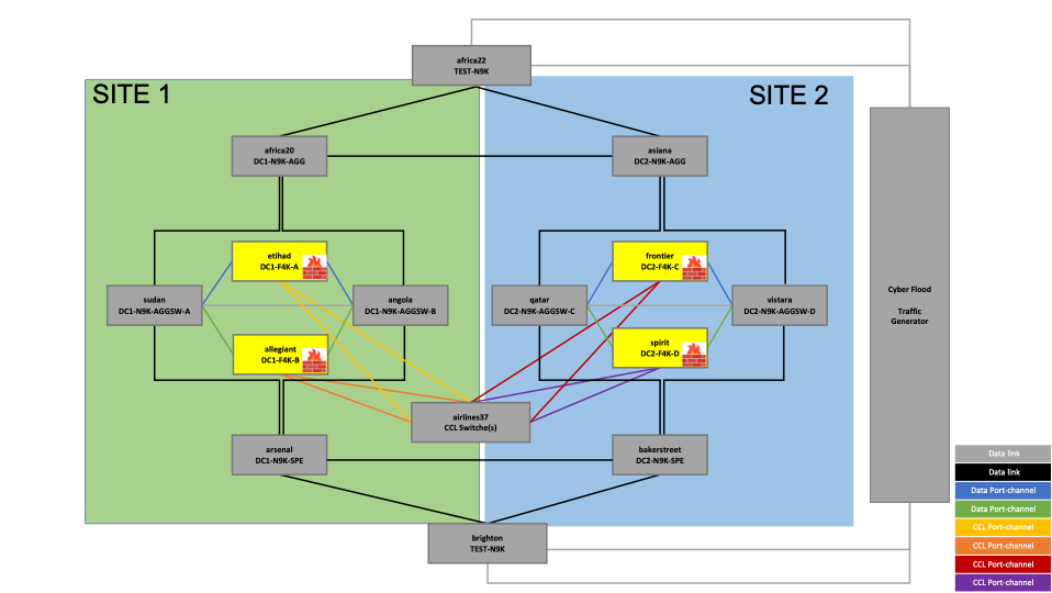
Figure 1. Reference topology - Firewalls
The highlighted devices in the above topology are the firewalls across two sites – SITE 1 and SITE 2.
The firewalls in SITE 1 are:
- etihad
- allegiant
The firewalls in SITE 2 are:
- frontier
- spirit
b. CCL Switch
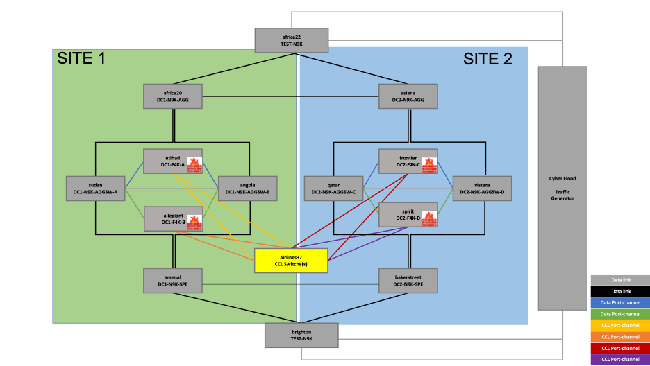
Figure 2. Reference topology – CCL Switch
The Cluster Control Link (CCL) switch that controls all the CCL traffic through the cluster is:
• airlines37
The same switch is used for both sites in this topology, which refers to the requirement of the CCL link being stretched at Layer 2.
c. Data Switches
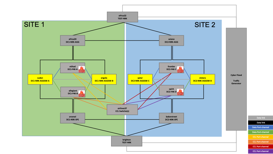
Figure 3 – Reference Topology – Data Switches
The data switches connecting the data interfaces of the cluster are as follows:
In SITE1:
- sudan
- angola
In SITE2:
- qatar
- Vistara
d. Load Balancing Routers
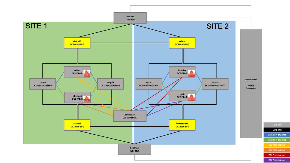
Figure 4 – Reference topology – Load Balancing Routers
As mentioned earlier, in Individual Interface mode cluster, the load balancing is done by the connected routers. In this topology, the load balancing to the cluster is done by the routing protocol BGP, with neighborship established between the highlighted routers (as shown in the above topology) and the firewall units:
In SITE1:
- africa20
- arsenal
In SITE2:
- asiana
- bakerstreet
e. Client and Server-facing Switches
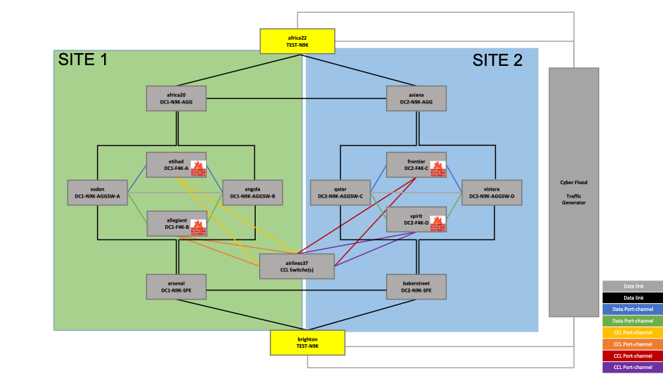
Figure 5 – Reference topology – Client and Server-facing Switches
The switches facing the traffic generator are as follows:
- africa22 – Client-side
- brighton – Server-side
The IP subnets 10.101.0.0/16 (client) and 20.201.0.0/16 (server) are preferred over SITE1 and the IP subnets 10.102.0.0/16 (client) and 20.202.0.0/16 (server) are preferred over SITE 2.
Configuration
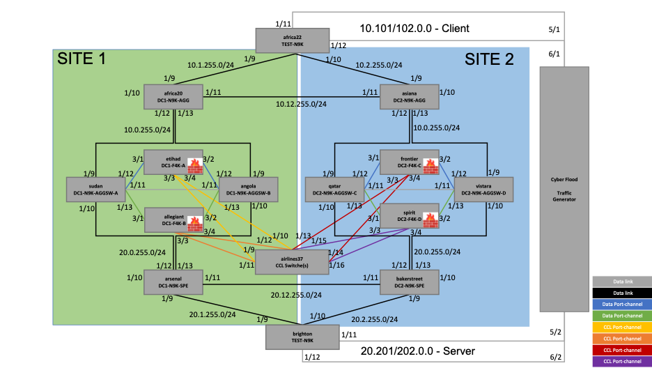
Figure 6 – Reference topology with interface and IP address details
The configuration snippets shown in the document are all from the CLI, including those for the firewalls. However, the firewalls used are FTD and the configuration was done via the Firewall Management Center UI.
a. Firewall (Etihad)
Cluster configuration:
cluster group cluster
 local-unit fp4245-1
 cluster-interface Port-channel48 ip 10.10.4.1 255.255.255.224
 priority 1
 health-check holdtime 3
 health-check data-interface auto-rejoin 3 5 2
 health-check cluster-interface auto-rejoin unlimited 5 1
 health-check system auto-rejoin 3 5 2
 health-check monitor-interface debounce-time 500
 site-id 1
 site-redundancy
 no health-check monitor-interface Management1/1
 no health-check monitor-interface Management1/2
 enable
 director-localization
no cluster replication delay http
!
The firewall units are named as follows:
• etihad - fp4245-1
• allegiant - fp4245-2
• frontier - fp4245-3
• spirit - fp4245-4
The SITE IDs configured are as follows:
• etihad – site-id 1
• allegiant – site-id 1
• frontier – site-id 2
• spirit – site-id 2
The CCL subnet used is 10.10.4.1/255.255.255.224, so each firewall is assigned an IP each from this subnet.
Interface configuration:
bfd-template single-hop BFDTemplate
 interval min-tx 100 min-rx 100 multiplier 3
!
ip local pool Inside-pool 10.0.255.10-10.0.255.15 mask 255.255.255.0
ip local pool Outside-pool 20.0.255.10-20.0.255.15 mask 255.255.255.0
!
interface Port-channel1
 nameif data
 security-level 0
 no ip address
!
interface Port-channel1.10
 vlan 10
 nameif outside
 security-level 0
 ip address 10.0.255.16 255.255.255.0 cluster-pool Inside-pool
 bfd template BFDTemplate
!
interface Port-channel1.20
 vlan 20
 nameif inside
 security-level 0
 ip address 20.0.255.16 255.255.255.0 cluster-pool Outside-pool
 bfd template BFDTemplate
!
Bidirectional Forwarding Detection (BFD) is enabled on the interfaces intended for a direct, single-hop connection. It is a very fast protocol used to detect failures in the forwarding path between two devices by sending small, periodic "hello" packets to its neighbor. If a certain number of these packets are missed, BFD quickly declares the link or path down.
The IP addresses 10.0.255.16/255.255.255.0 and 20.0.255.16/255.255.255.0 are the main cluster IP addresses which belong to the control node eithad. All the nodes in the cluster, including the control node, get an IP address from the configured cluster pool.
BGP configuration:
ip local pool clusterpool 0.0.0.1-0.0.0.4 mask 255.255.255.0
router bgp 65000
 bgp log-neighbor-changes
 bgp router-id cluster-pool clusterpool
 address-family ipv4 unicast
  neighbor 10.0.255.1 remote-as 65111
  neighbor 10.0.255.1 ebgp-multihop 255
  neighbor 10.0.255.1 transport path-mtu-discovery disable
  neighbor 10.0.255.1 fall-over bfd single-hop
  neighbor 10.0.255.1 activate
  neighbor 20.0.255.1 remote-as 65112
  neighbor 20.0.255.1 ebgp-multihop 255
  neighbor 20.0.255.1 transport path-mtu-discovery disable
  neighbor 20.0.255.1 fall-over bfd single-hop
  neighbor 20.0.255.1 activate
  neighbor 10.0.255.2 remote-as 65001
  neighbor 10.0.255.2 ebgp-multihop 255
  neighbor 10.0.255.2 transport path-mtu-discovery disable
  neighbor 10.0.255.2 fall-over bfd single-hop
  neighbor 10.0.255.2 activate
  neighbor 20.0.255.2 remote-as 65002
  neighbor 20.0.255.2 ebgp-multihop 255
  neighbor 20.0.255.2 transport path-mtu-discovery disable
  neighbor 20.0.255.2 fall-over bfd single-hop
  neighbor 20.0.255.2 activate
  redistribute connected
  no auto-summary
  no synchronization
 exit-address-family
!
The BGP neighbors configured are:
• africa20 (10.0.255.1)
• arsenal (20.0.255.1)
• asiana (10.0.255.2)
• bakerstreet (20.0.255.2)
b. CCL Switch (airlines37)
Interface configuration:
vlan 1,48
vlan 48
  name clusterlink
interface port-channel1
  switchport
  switchport access vlan 48
  spanning-tree port type edge
  mtu 9000
interface port-channel2
  switchport
  switchport access vlan 48
  spanning-tree port type edge
  mtu 9000
interface port-channel3
  switchport
  switchport access vlan 48
  spanning-tree port type edge
  mtu 9000
interface port-channel4
  switchport
  switchport access vlan 48
  spanning-tree port type edge
  mtu 9000
interface Ethernet1/9
  switchport
  switchport access vlan 48
  mtu 9000
  channel-group 1 mode active
  no shutdown
interface Ethernet1/10
  switchport
  switchport access vlan 48
  mtu 9000
  channel-group 1 mode active
  no shutdown
interface Ethernet1/11
  switchport
  switchport access vlan 48
  mtu 9000
  channel-group 2 mode active
  no shutdown
interface Ethernet1/12
  switchport
  switchport access vlan 48
  mtu 9000
  channel-group 2 mode active
  no shutdown
interface Ethernet1/13
  switchport
  switchport access vlan 48
  mtu 9000
  channel-group 3 mode active
  no shutdown
interface Ethernet1/14
  switchport
  switchport access vlan 48
  mtu 9000
  channel-group 3 mode active
  no shutdown
interface Ethernet1/15
  switchport
  switchport access vlan 48
  mtu 9000
  channel-group 4 mode active
  no shutdown
interface Ethernet1/16
  switchport
  switchport access vlan 48
  mtu 9000
  channel-group 4 mode active
  no shutdown
The interfaces from each firewall are configured as a Port-Channel. For example, Ethernet 1/9 and Ethernet 1/10 connecting to etihad form Port-Channel 1, Ethernet 1/11 and Ethernet1/12 connecting to allegiant form Port-Channel 2, and so on.
c. Data Switches
c.1. Sudan
VPC configuration:
vpc domain 10
  peer-switch
  peer-keepalive destination 198.18.175.138 source 198.18.175.135
c.2. Angola
VPC configuration:
vpc domain 10
  peer-switch
  peer-keepalive destination 198.18.175.135 source 198.18.175.138
The switches sudan and angola in SITE1 form a VPC pair. Similarly, qatar and vistara in SITE 2 form a VPC pair. Ethernet 1/11 is used as the VPC peer-link.
c.1. Sudan
Interface configuration:
vlan 1,10,20
interface port-channel9
  switchport
  switchport access vlan 10
  spanning-tree port type edge
  vpc 9
interface port-channel10
  switchport
  switchport access vlan 20
  spanning-tree port type edge
  vpc 10
interface port-channel11
  switchport
  switchport mode trunk
  spanning-tree port type network
  vpc peer-link
interface port-channel12
  switchport
  switchport mode trunk
  spanning-tree port type edge trunk
  vpc 12
interface port-channel13
  switchport
  switchport mode trunk
  spanning-tree port type edge trunk
  vpc 13
interface Ethernet1/9
  switchport
  switchport access vlan 10
  channel-group 9 mode active
  no shutdown
interface Ethernet1/10
  switchport
  switchport access vlan 20
  channel-group 10 mode active
  no shutdown
interface Ethernet1/11
  switchport
  switchport mode trunk
  channel-group 11 mode active
  no shutdown
interface Ethernet1/12
  switchport
  switchport mode trunk
  channel-group 12 mode active
  no shutdown
interface Ethernet1/13
  switchport
  switchport mode trunk
  channel-group 13 mode active
  no shutdown
Interfaces Ethernet 1/9 and Ethernet 1/10 belong to Vlan 10 and 20, respectively. Interfaces Ethernet 1/12 and Ethernet 1/13 are configured as trunk ports, as they are connected to the firewall cluster’s sub-interfaces.
d. Load-balancing routers (africa20):
Interface configuration:
vlan 1,10,20
vlan 10
  name Inside
vlan 20
  name Outside
route-map anyany permit 10
  match ip address any
interface port-channel9
  bfd interval 100 min_rx 100 multiplier 3
  ip address 10.0.255.1/24
interface Ethernet1/9
  bfd interval 100 min_rx 100 multiplier 3
  ip address 10.1.255.9/24
  no shutdown

interface Ethernet1/10
  bfd interval 100 min_rx 100 multiplier 3
interface Ethernet1/11
  bfd interval 100 min_rx 100 multiplier 3
  ip address 10.12.255.1/24
  no shutdown
interface Ethernet1/12
  channel-group 9 mode active
  no shutdown
interface Ethernet1/13
  channel-group 9 mode active
  no shutdown
Interfaces Ethernet 1/12 and Ethernet 1/13 are bundled into a Port-Channel which establishes BGP neighborship with the firewalls.
BGP configuration:
router bgp 65111
  address-family ipv4 unicast
    redistribute direct route-map anyany
    redistribute static route-map anyany
    maximum-paths 2
  neighbor 10.0.255.10
    bfd
    remote-as 65000
    address-family ipv4 unicast
  neighbor 10.0.255.11
    bfd
    remote-as 65000
    address-family ipv4 unicast
  neighbor 10.0.255.12
    bfd
    remote-as 65000
    address-family ipv4 unicast
  neighbor 10.0.255.13
    bfd
    remote-as 65000
    address-family ipv4 unicast
  neighbor 10.0.255.14
    bfd
    remote-as 65000
    address-family ipv4 unicast
  neighbor 10.0.255.15
    bfd
    remote-as 65000
    address-family ipv4 unicast
  neighbor 10.1.255.1
    bfd
    remote-as 65011
    address-family ipv4 unicast
  neighbor 10.12.255.2
    bfd
    remote-as 65001
    address-family ipv4 unicast
10.0.255.10-10.0.255.15/255.255.255.0 is the Inside pool configured on the firewall. Note that each IP address in the pool is configured as a BGP neighbor on the router. The BGP neighborship is with the Inside pool on africa20 in SITE 1 and asiana in SITE 2. Whereas, the BGP neighborship is with the Outside pool on arsenal in Site1 and bakerstreet in Site2.
In this example, asiana and africa22 have also been configured as BGP neighbors on africa20.
e. Client and Server facing Switches (africa22):
Interface configuration:
interface Ethernet1/9
  bfd interval 100 min_rx 100 multiplier 3
  ip address 10.1.255.1/24
  no shutdown
interface Ethernet1/10
  bfd interval 100 min_rx 100 multiplier 3
  ip address 10.2.255.1/24
  no shutdown
interface Ethernet1/11
  switchport
  switchport mode trunk
  spanning-tree port type edge trunk
  no shutdown
interface Ethernet1/12
  switchport
  switchport mode trunk
  spanning-tree port type edge trunk
  no shutdown
Interfaces Ethernet1/11 and Ethernet1/12 connecting the traffic generator are configured as trunk ports.
BGP configuration with route-map:
ip prefix-list 201 seq 5 permit 20.201.0.0/16
ip prefix-list 202 seq 5 permit 20.202.0.0/16
route-map FROM-Site1 permit 10
  match ip address prefix-list 201
  set weight 40000
route-map FROM-Site1 permit 100
  match ip address prefix-list 202
route-map FROM-Site2 permit 10
  match ip address prefix-list 202
  set weight 40000
route-map FROM-Site2 permit 100
  match ip address prefix-list 201
route-map anyany permit 10
  match ip address any
router bgp 65011
  address-family ipv4 unicast
    redistribute direct route-map anyany
    redistribute static route-map anyany
    maximum-paths 2
  neighbor 10.1.255.9
    bfd
    remote-as 65111
    address-family ipv4 unicast
      route-map FROM-Site1 in
  neighbor 10.2.255.9
    bfd
    remote-as 65001
    address-family ipv4 unicast
      route-map FROM-Site2 in
The route-maps are configured to prefer 20.201.0.0/16 over SITE 1 and 20.202.0.0/16 over SITE 2. Similarly, brighton is configured to prefer 10.101.0.0/16 over SITE 1 and 10.102.0.0/16 over SITE 2.
BGP Neighborship
The BGP neighborship established between the firewalls and the routers is as shown in the figure below. If both the neighbors (etihad and allegiant) of africa20 go down (for instance), another route is preferred via asiana towards the server subnet.
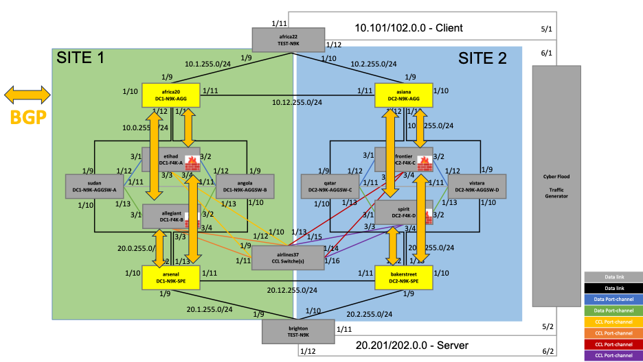
Figure7 - BGP neighborship
Let's have a closer look at the BGP neighborship between one of the routers and one of the firewalls: africa20 and allegiant, respectively.
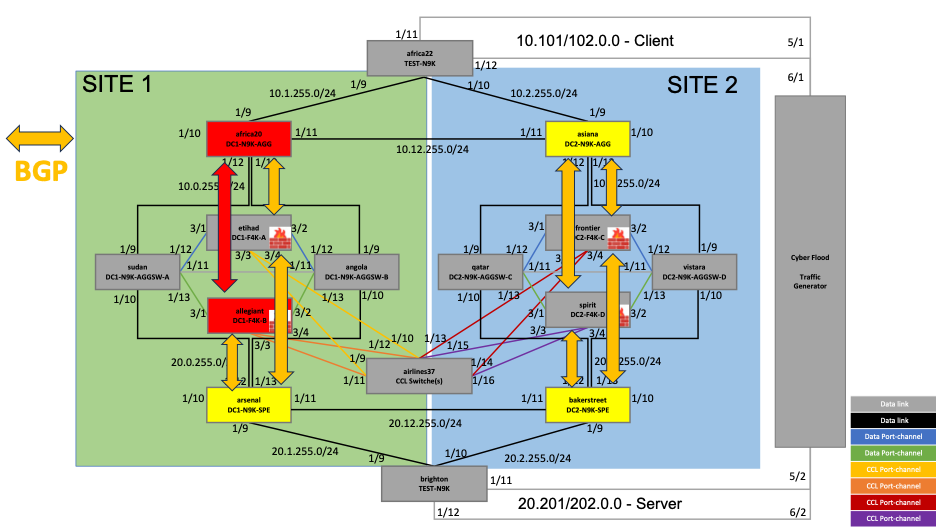
Figure 8 – BGP neighborship between africa20 and allegiant
All four routers have been configured as BGP neighbors on the firewall cluster. This can be viewed on the FMC as shown below:
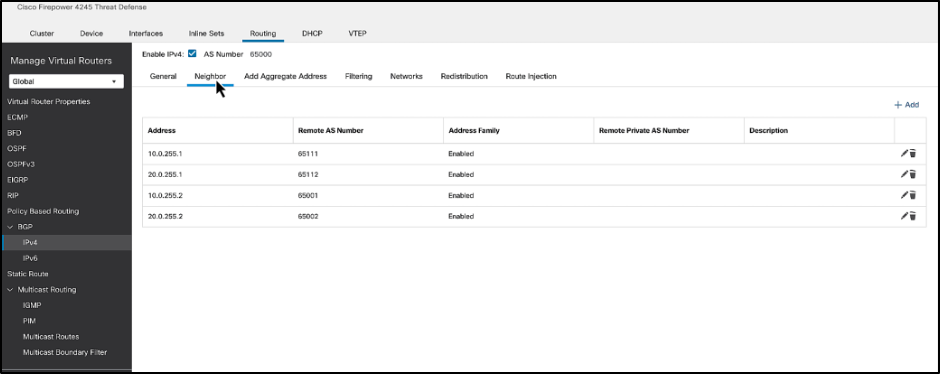
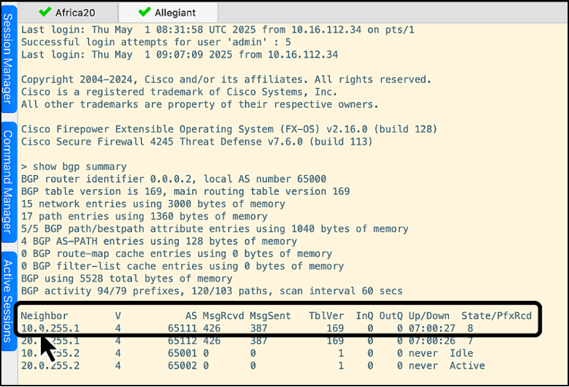
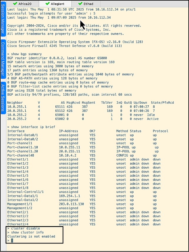
Let's log into the CLI of allegiant to show the BGP neighbors. The router, africa20 (10.0.255.1), is highlighted in the screenshot below:
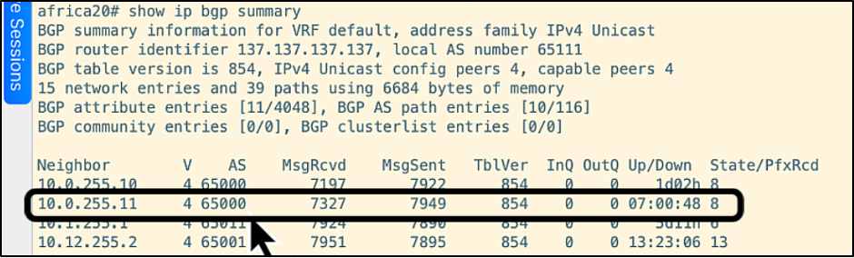
We'll now log into the CLI of africa20 to show its BGP neighbors. The allegiant firewall (10.0.255.11) is highlighted in the screenshot below:
Traffic Flow
The traffic flow through the cluster comes from Cyberflood, a traffic generator tool. The flow through one of the firewall units (etihad) is shown below.
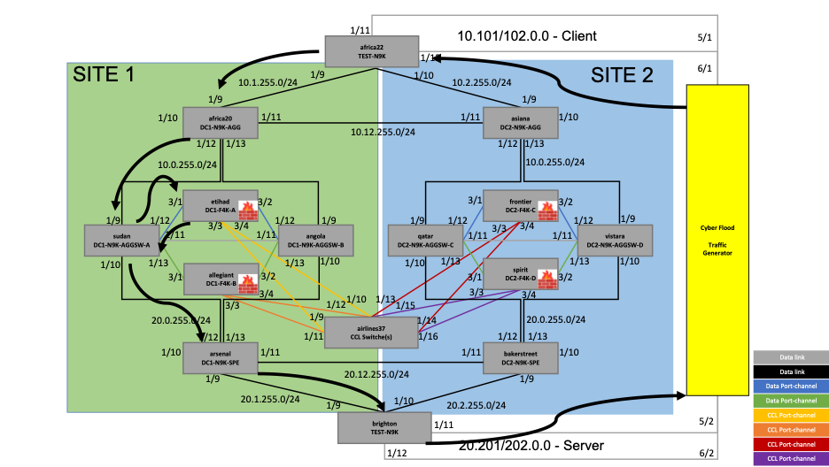
Figure9- Traffic flow through the firewall unit etihad
The traffic is generated and flows into africa22 which is the client side. The router, africa22, routes the traffic to africa20 based on the route learnt via BGP. The traffic is then load-balanced to etihad, based on BGP routes. The traffic is inspected at the firewall and routed to arsenal. The router, arsenal, routes the traffic to brighton, where the traffic flows back to Cyberflood on the server side.
Resiliency Tests
Let us now explore how an Individual Interface mode cluster can withstand different failure scenarios showcasing the true stateful redundancy capability of a cluster.
Note: the test scenarios were run using CLI commands on the firewalls, but most of the outputs can be viewed in graphical format via the Cluster Health monitoring dashboard as well. Check out the video on Cluster Health monitoring dashboard here - Cluster Health Monitor
The resiliency tests done on the cluster are as follows:
• Firewall Node failure
• Degraded Node Management
• Site Failure
Firewall Node Failure
In this test, one of the nodes is brought down by first disabling the node via 'cluster disable' command, which is a graceful failure, and next, by failing Firewall Data Interfaces, which is a non-graceful failure.
a. Graceful Node Failure

Figure 10 – Resiliency Test – Graceful Node Failure
The firewall unit allegiant in SITE 1 is failed by running the command ‘cluster disable’. Below are the steps followed for the same:
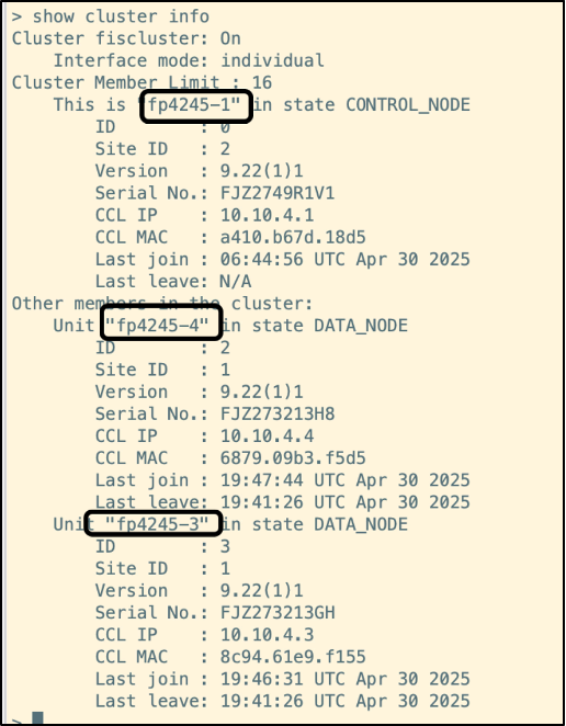
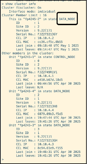
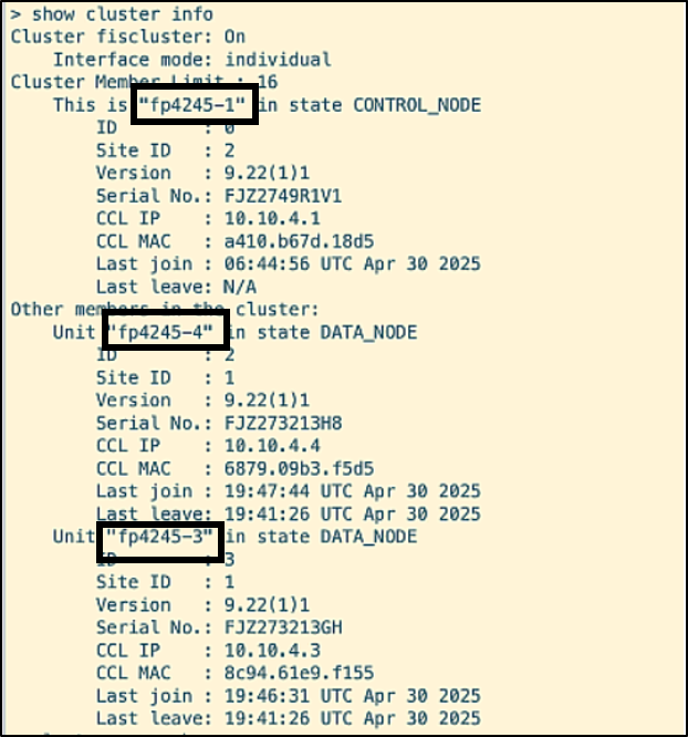
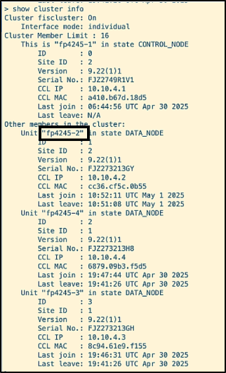
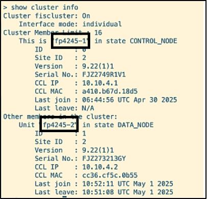
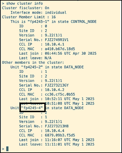
- The cluster health is checked by running the command ‘show cluster info’ on one of the units. The output below shows the result of the command when run on the unit etihad.
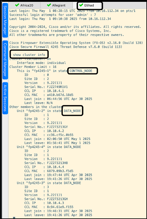
As per the output, etihad is the Control Node, and the rest of the units are Data Nodes. You can also spot the Interface mode of the cluster mentioned, which is ‘Individual’.
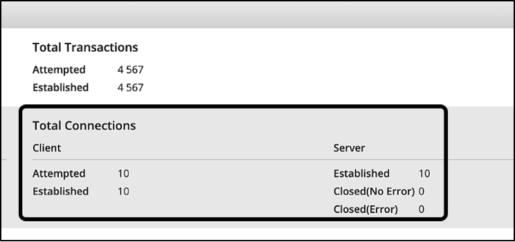
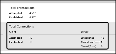
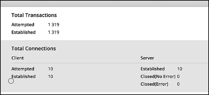
- On the traffic generator, Cyberflood, traffic flow through the cluster is initiated.
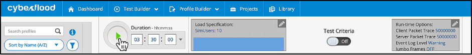
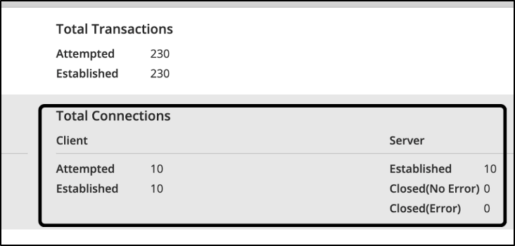
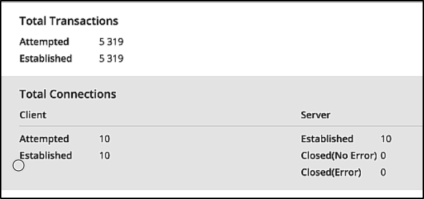
In the below screenshot, taken from Cyberflood, you see that all the connections have been established.
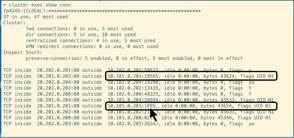
The below CLI output is obtained by running the command ‘cluster exec show conn’. Let us focus on the highlighted connections with destination ports 10565 and 1885 established on the unit fp4245-2, which is allegiant.
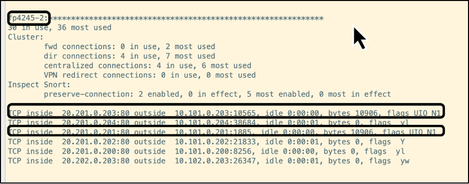
NOTE
The flags assigned give an indication of the connection role of the node for a particular flow as per the below chart:
Connection Role Flag(s) Owner UIO Director Y Backup owner Y (if the director is also the backup owner) y (if the director is not the backup owner)
The flows highlighted above have the flag ‘UIO’, which means that the connection is owned by the firewall fp4245-2, i.e., allegiant.
- The command ‘cluster disable’ is run on allegiant. The output of the command ‘show cluster info’ verifies that clustering is disabled on the unit.
Running the command ‘show cluster info’ now on the control node etihad, shows that fp4245-2 (allegiant) is removed from the cluster.
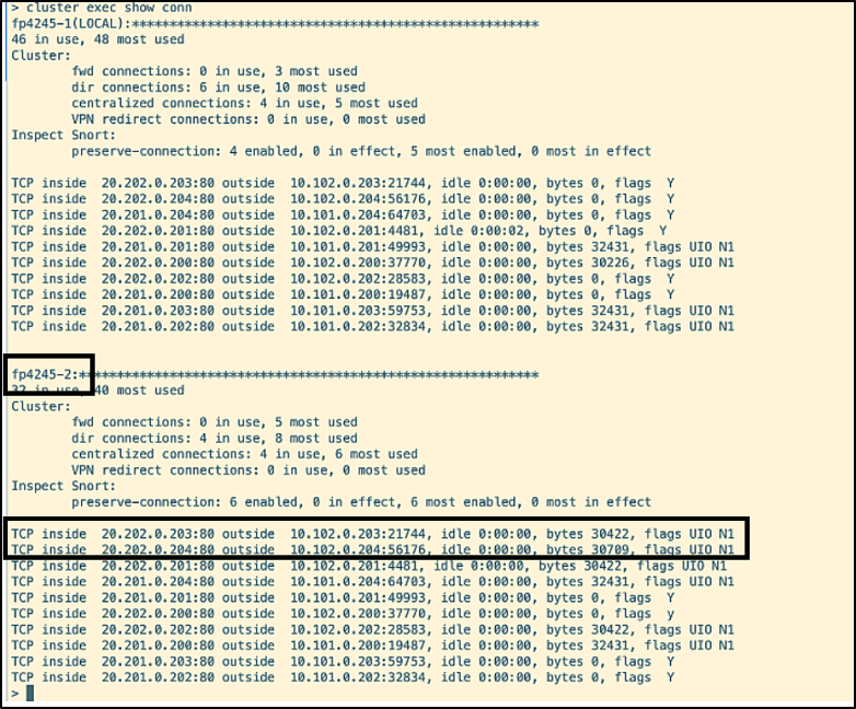
- Running the command ‘cluster exec show conn’ shows that the connections that were established on allegiant have now moved to other units seamlessly. Let us verify this by looking at the connections with destination ports 10565 and 1885 identified in step 2.
In the above screenshot you see that the connections have been moved to fp4245-1 (etihad).
On Cyberflood, no connection errors are seen at this stage:
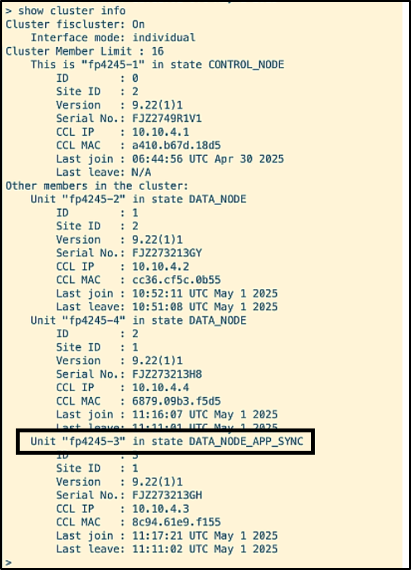
- The cluster is now enabled back on allegiant by running the command ‘cluster enable’. Verifying the cluster status shows that the node has entered DATA_NODE_APP_SYNC state.
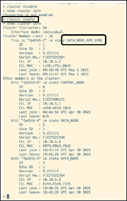
After the synchronization is done, it navigates to DATA_NODE state.
On the Cyberflood, you can also verify that no connection has been dropped in the event of the firewall re-joining the cluster.
This concludes the first test, graceful node failure.
b. Non-Graceful Node Failure
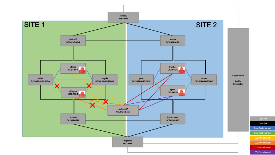
Figure 11 – Resiliency Test – Non-graceful Node Failure
In the second test of node failure, all the data and CCL interfaces of the allegiant firewall node in SITE 1 are brought down via an EEM Script. Let's have a look at the EEM scripts.
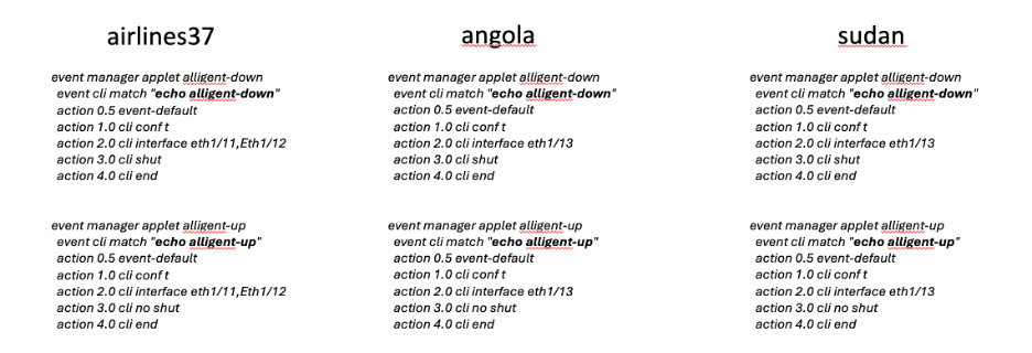
‘echo allegiant-down’ script brings down all the data and CCL interfaces on allegiant, and ‘echo alligiant-up’ script brings back the interfaces.
Below are the steps followed for the same:
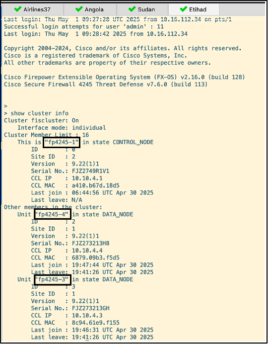
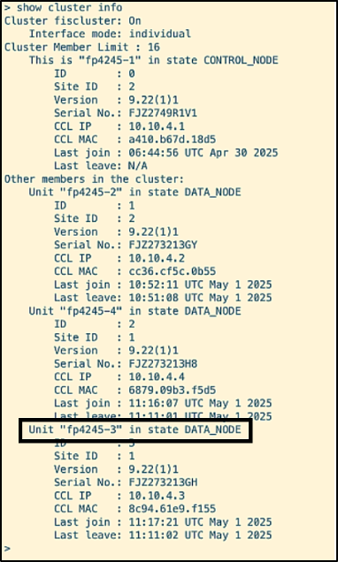
- The cluster is verified to be up and running with all four nodes via the command ‘show cluster info’
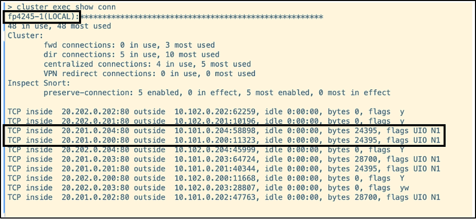
- Traffic is generated from Cyberflood through the cluster.
Let's focus on the highlighted connections with destination ports 58898 and 11323.
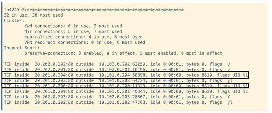
- The script ‘echo allegiant-down’ is run across airlines37, sudan and angola. The command ‘show cluster info’ shows that allegiant (fp-4245-2) is no longer part of the cluster.
The highlighted connections with destination ports 58898 and 11323 are moved to etihad from allegiant:
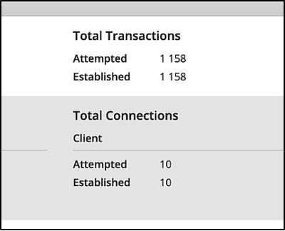
The connection status is verified from Cyberflood as well, which is all up and running.
- The script ‘echo allegiant-up’ is run across airlines37, sudan and angola to bring back all the data and CCL interfaces of allegiant. The command ‘show cluster info’ shows that allegiant (fp-4245-2) has rejoined the cluster.
The connections seen on Cyberflood are still stable.
Degraded Node
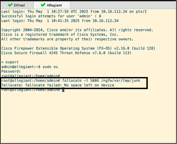
One of the nodes (allegiant again) is brought down by simulating a full disk scenario by generating a big size file on its disk.
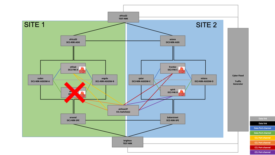
Figure 12 – Resiliency Test – Degraded Node
The steps followed for this are as below:
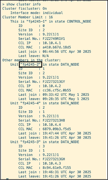
- The cluster status is verified by running the command ‘show cluster info’.
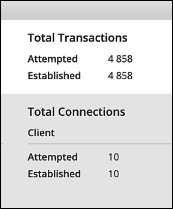
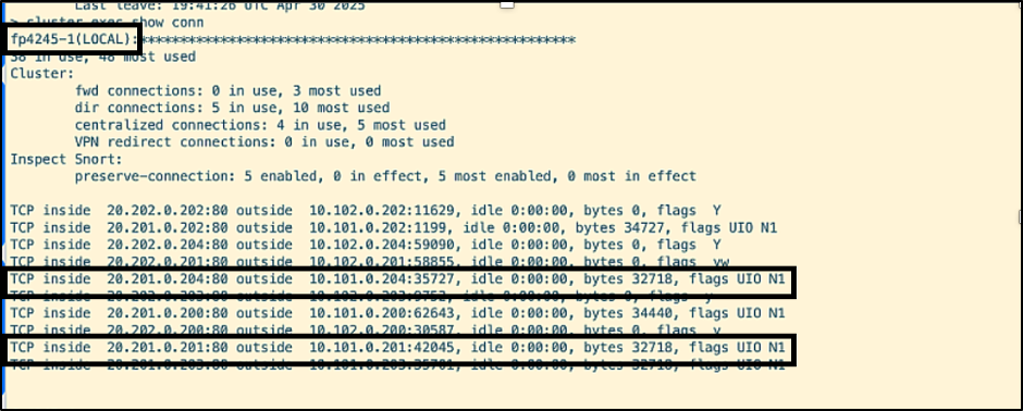
- Traffic is initiated to the cluster from Cyberflood. Note the connections on allegiant with destination ports 35727 and 42045.
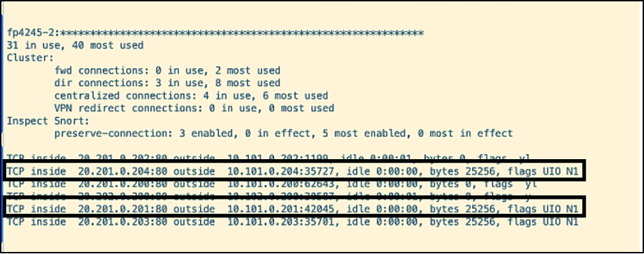
- Disk space simulation command is run on allegiant.
The node gets kicked out of the cluster, as seen below.
The connections with ports 35727 and 42045 are moved to etihad.
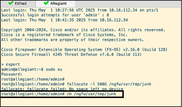
- Removing the file frees up disk space from allegiant and brings it back to normal, eligible to rejoin the cluster.
Site Failure
In this test, one of the sites, SITE 2 in this example, is brought down by running an EEM script to fail all the interfaces of the firewalls, switches, and routers in this site.
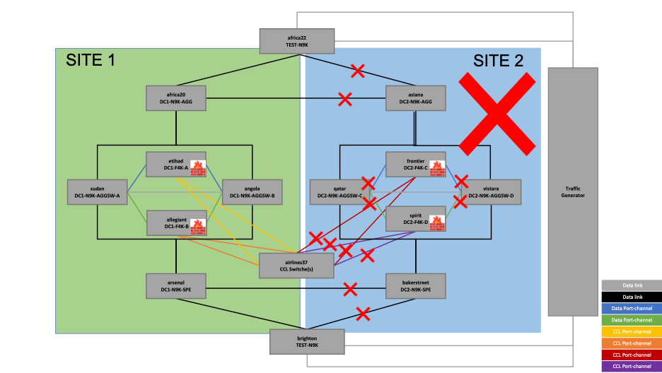
Figure 13- Resiliency Test – Site Failure
The EEM scripts are as below:
Site Down script:
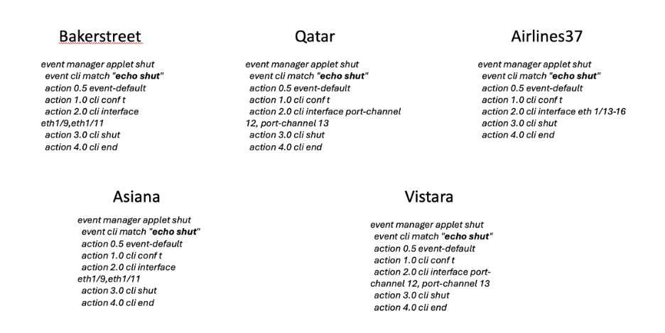
The ‘echo shut’ script brings down all the interfaces in SITE 2 by running it on all the above-mentioned devices.
Site Up script:
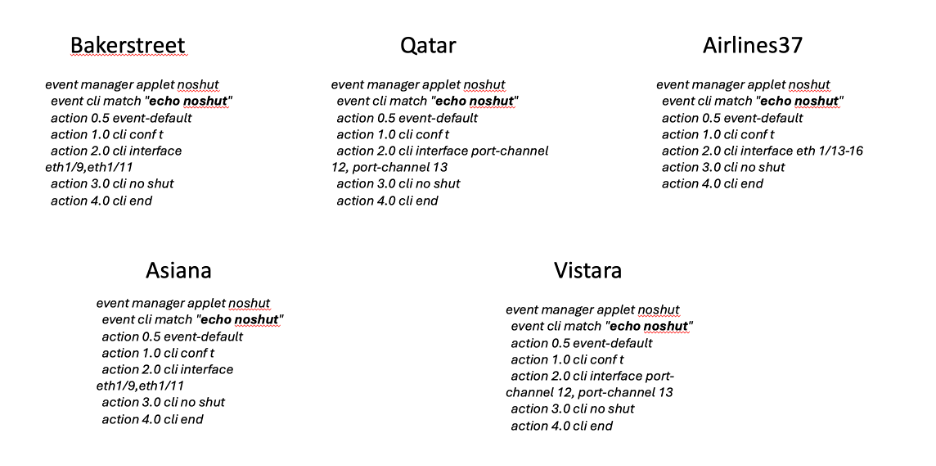
The ‘echo noshut’ script brings back up all the interfaces in SITE 2 by running it on the same set of devices.
The steps followed are as below:
- The firewall cluster status is verified
- Traffic is generated from Cyberflood
- The connections built on frontier (f4245-3) and spirit (f4245-4) are highlighted with destination port 21744 on frontier and destination port 56176 on spirit.
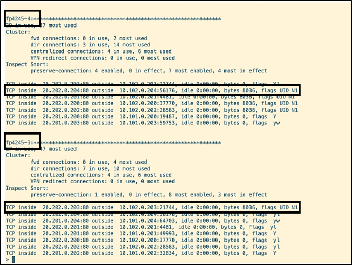
- The script 'echo shut' is executed on bakersteet, qatar, asiana, vistara and airlines37 to shut down its interfaces having connections on SITE 2, which results in the removal of the firewalls frontier and spirit from the cluster.
The connections from these firewalls are moved to etihad and allegiant in SITE 1 seamlessly. The ones with ports 21744 and 56176 are moved to allegiant.
The connections are up and running on Cyberflood.
- The script noshut is run to bring back all the interfaces in SITE 2 that were shut down previously. The nodes frontier and spirit rejoin the cluster one after the other.
Note
In the upcoming release parallel join feature is being added to ASA cluster, in which multiple nodes can join the cluster simultaneously.
The node spirit (f4245-4) has first joined the cluster.
The node frontier (f4245-3) is now transitioning to DATA_NODE_APP_SYNC.
The node frontier (f4245-3) has transitioned to DATA_NODE state, resulting in the cluster having all the nodes up and running.
Cyberflood status shows that the connections are all up with no closed errors.
Conclusion
This document comprehensively details the reference architecture for Cisco Secure Firewall Clustering in an Individual Interface mode deployment, highlighting its design principles, configuration specifics, and operational aspects.
The resiliency tests conducted—including graceful and non-graceful individual node failures, degraded node scenarios, and complete site outages—demonstrate the robust high availability and disaster recovery capabilities of Cisco Secure Firewall clustering solution. In all simulated failure scenarios, the cluster successfully maintained stateful connections and ensured continuous traffic flow, confirming its ability to provide uninterrupted security enforcement and network services across geographically dispersed locations. This architecture proves to be a highly resilient and scalable solution for critical network infrastructures.
Updated 12 months ago