Simplified Branch to Hub Tunnel
Cisco Internal Use Only for Secure Firewall Roadshow Ignite Event
A Site-to-Site Virtual Private Network (VPN) is a network connection that enables secure communication between two or more geographically separated sites over a public network, such as the internet. The primary purpose of a Site-to-Site VPN is to establish a secure and encrypted communication channel between different locations, allowing organizations to connect their remote offices, data centers, or branch offices securely.
Learning Objectives
Upon completion of this lab, you will be able to:
- Configure Site to Site (S2S) VPN from the On-Prem FMC for simplified branch to hub communication
- Understand EIGRP routing between two internal networks shared over a VPN tunnel.
Understanding the lab flow
- First we create two loopback interfaces, one emulating an internal network and another emulating VPN tunnel network on both NGFW1 and NGFW2.
- Next create a Virtual Tunnel Interfaces (VTIs) to enhance network capabilities for secure data transmission on both devices.
- Now we go over to create the Site to Site VPN Topology for the Hub and Spoke nodes.
- Then configure EIGRP on them so that they can share the internal networks through the VPN tunnel.
- Now we deploy the configuration to the devices and verify if EIGRP is working.
- Take a look at the active connection in the Site to Site Dashboard.
Topology
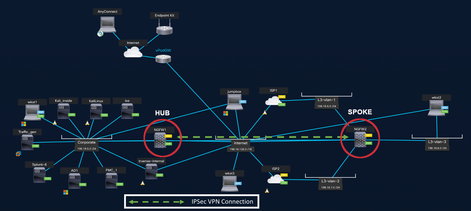
DVTI Hub and Spoke Topology
Lab Tasks Overview
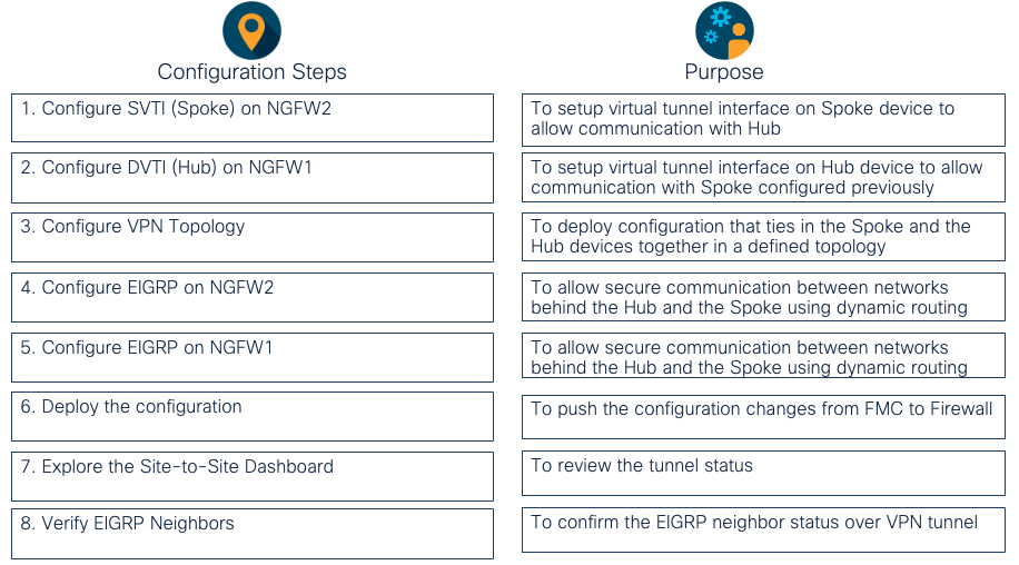
Task 1 - Configure SVTI on NGFW2 (Spoke)
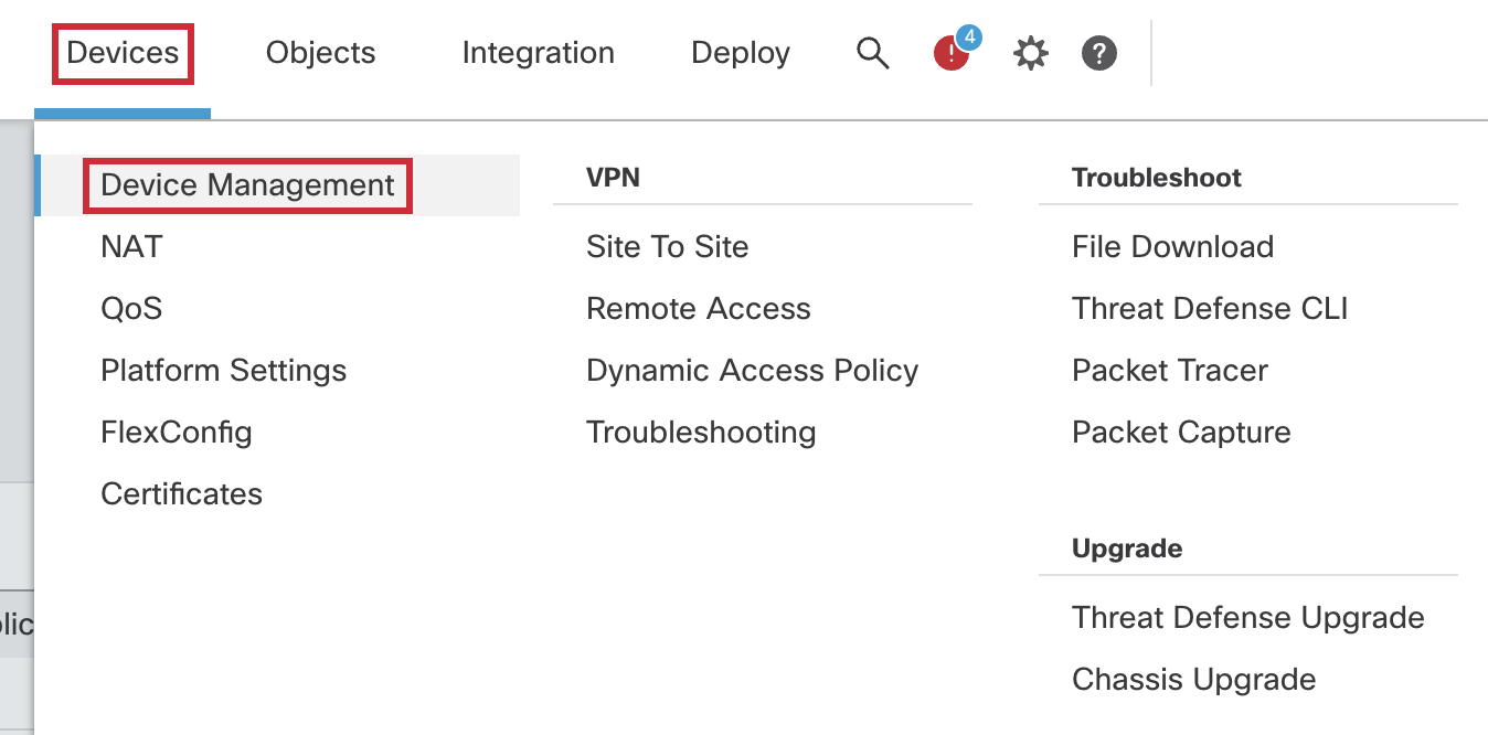
- Go to Device > Device Management and click the pencil (edit) icon next to NGFW2 which is the Spoke in our deployment.

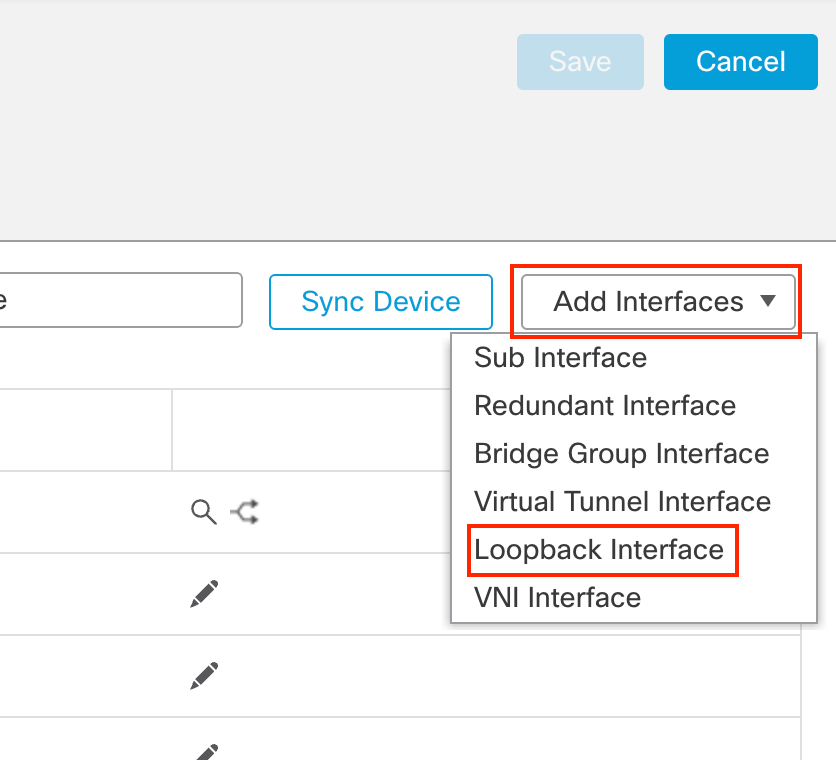
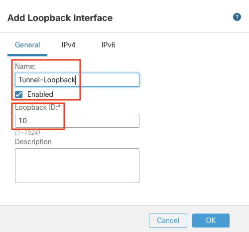
- Click on Add Interfaces > Loopback Interface to add a new loopback interface
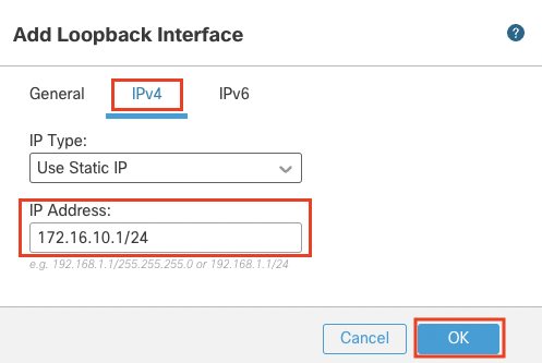
- In the pop up box, configure the following details:
- In the General Tab
- Name: Tunnel-Loopback
- Loopback ID: 10
- In the IPv4 Tab
- IP Address: 172.16.10.1/24
- In the General Tab
- Click on OK to save the interface.
- Click on Add Interfaces > Loopback Interface to add another loopback interface
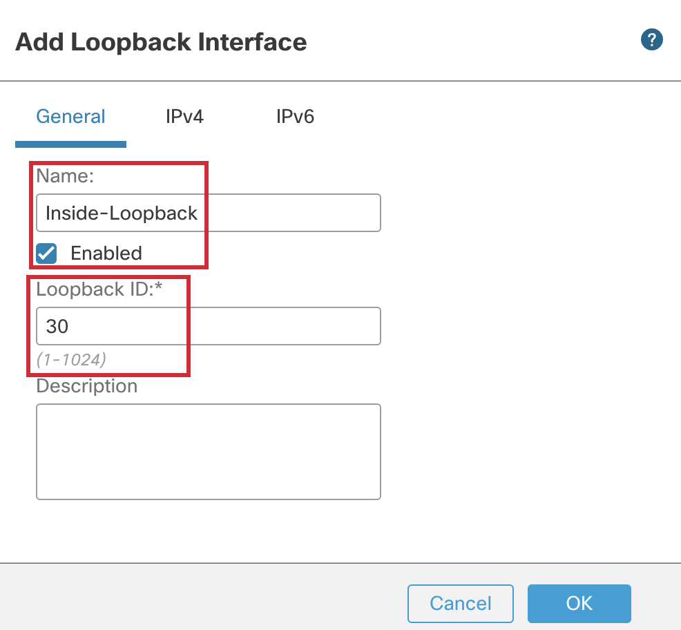
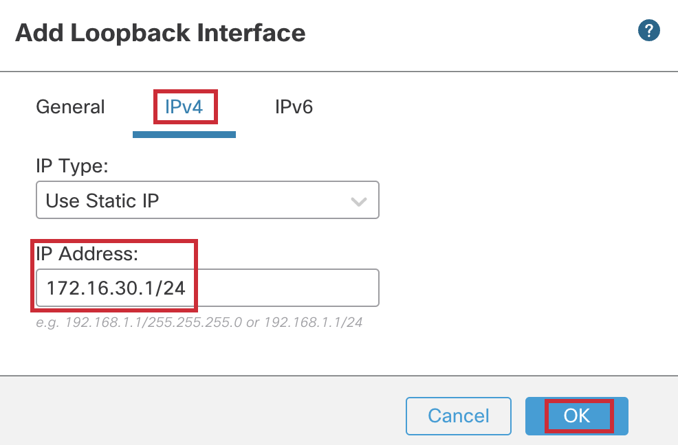
- In the pop up box, configure the following details:
- In the General Tab
- Name: Inside-Loopback
- Loopback ID: 30
- In the IPv4 Tab
- IP Address: 172.16.30.1/24
- In the General Tab
- Click on OK to save the interface.
Note
We employ two loopback interfaces for simulation purposes. The first one's IP address is used as Tunnel IP over which the tunnel will be established. The second one simulates the inside network, which would remain unreachable without the VPN and the necessary routing configurations.
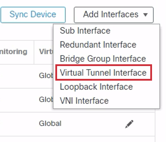
- Click on Add Interfaces > Virtual Tunnel Interface to add a VTI
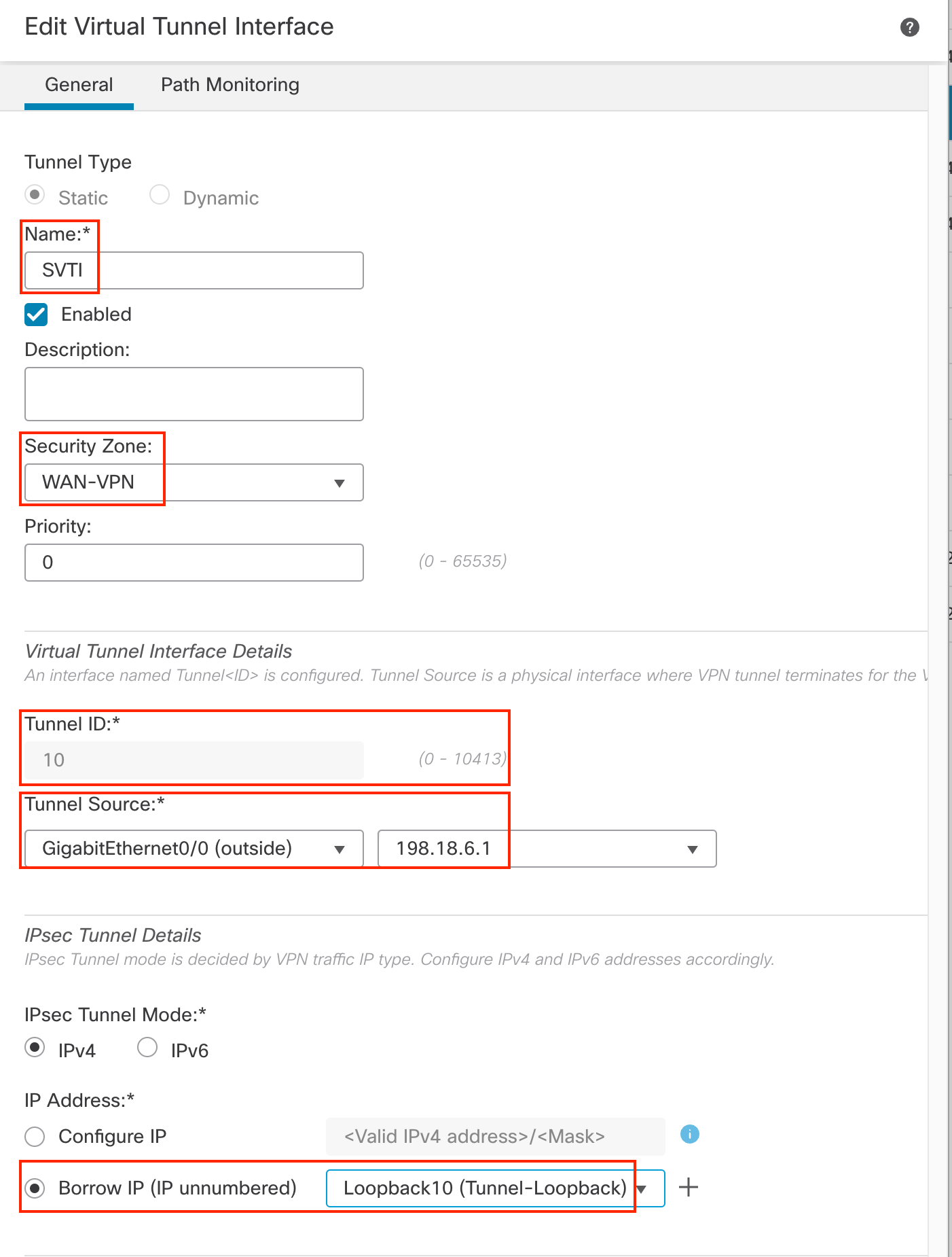
- In the pop up box, configure the following details:
- Tunnel Type: Static
- Name: SVTI
- Security Zone: From the drop-down, click on New to add a new zone named "WAN-VPN" and select this zone.
- Tunnel ID: 10
- Tunnel Source: GigabitEthernet0/0 (outside)
- Tunnel Source Address: 198.18.6.1 (outside interface IP address, available in the drop down once the tunnel source is selected)
- IP Address: Borrow IP (IP unnumbered). From the drop down next to it, select Loopback10 (Tunnel-Loopback)
- Click OK to save the SVTI
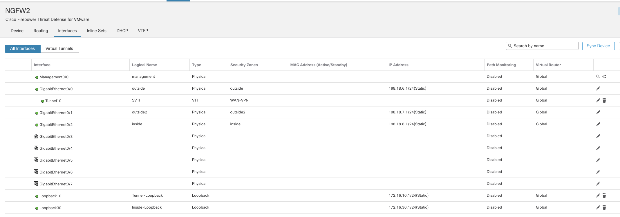
- Click Save button on the top right corner to save the interface created.
Task 2 - Configure DVTI on NFGW1 (Hub)
-
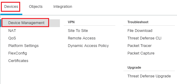
Go to Device > Device Management and click the pencil (edit) icon next to NGFW1 which is the Hub in our deployment.
-
Click on Add Interfaces > Loopback Interface to add a new loopback interface
-
In the pop up box, configure the following details:
- In the General Tab
- Name: Tunnel-Loopback
- Loopback ID: 10
- In the IPv4 Tab
- IP Address: 172.16.10.254/24
- In the General Tab
-
Click on OK to save the interface.

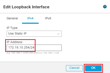
-
Click on Add Interfaces > Loopback Interface to add another loopback interface
-
In the pop up box, configure the following details:
- In the General Tab
- Name: Inside-Loopback
- Loopback ID: 20
- In the IPv4 Tab
- IP Address: 172.16.20.1/24
- In the General Tab
-
Click on OK to save the interface.
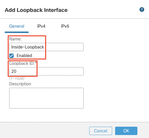
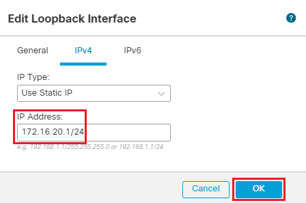
- Click on Add Interfaces > Virtual Tunnel Interface to add a VTI
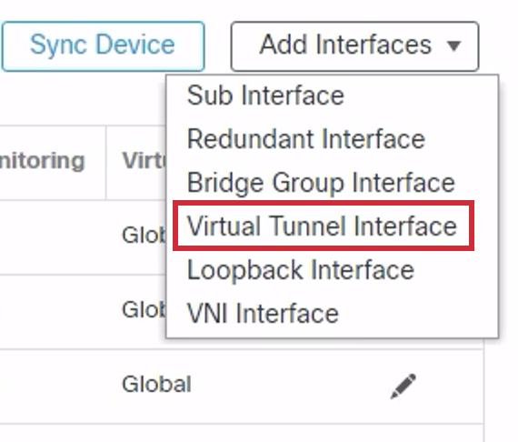
- In the pop up box, configure the following details:
- Tunnel Type: Dynamic
- Name: DVTI
- Security Zone: select WAN-VPN zone created in the last step.
- Tunnel ID: 10
- Tunnel Source: GigabitEthernet0/0 (outside)
- Tunnel Source Address: 198.18.133.81 (outside interface IP address, available in the drop down once the tunnel source is selected)
- IP Address: Borrow IP (IP unnumbered) will be selected by default. From the drop down next to it, select Loopback10 (Tunnel-Loopback).
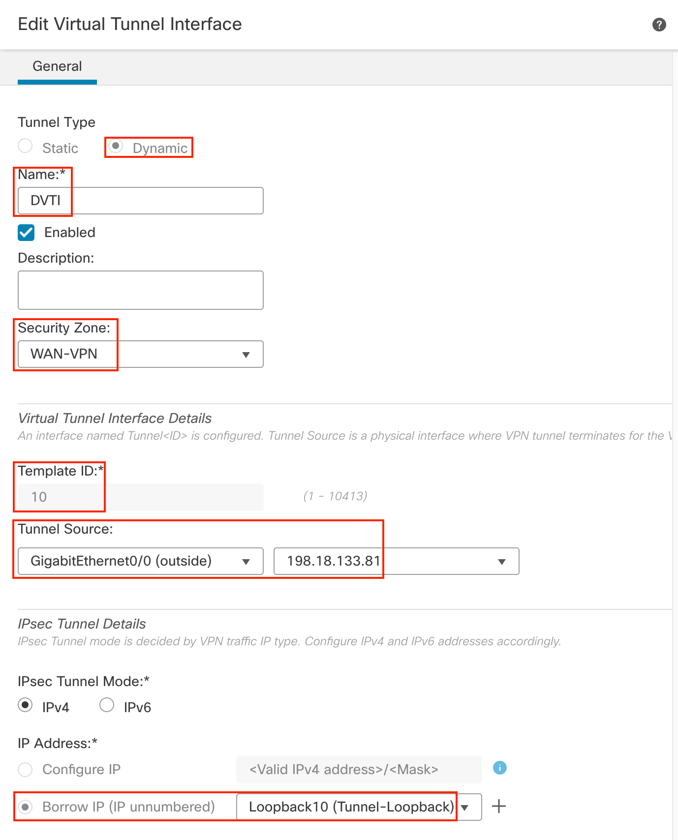
- Click OK to save the DVTI
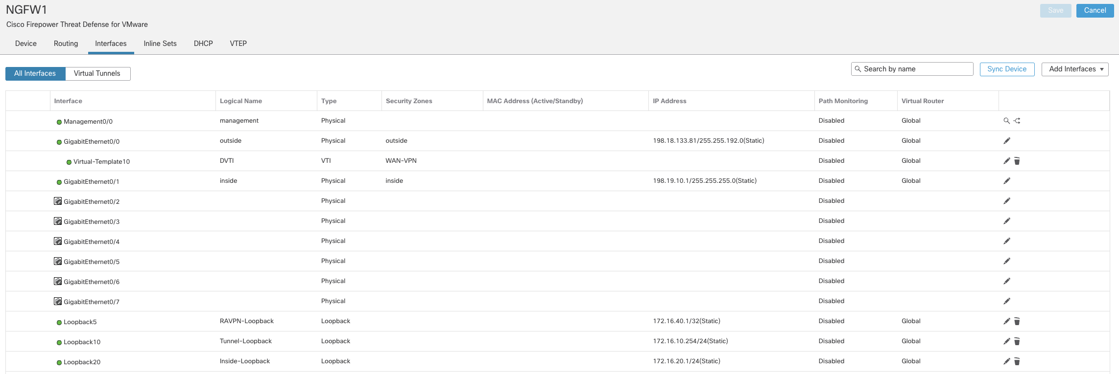
- Click Save button on the top right corner to save the interface created.
Task 3 - Configure VPN Topology
-
Go to Devices > VPN > Site to Site and
-
Click on + Site to Site VPN
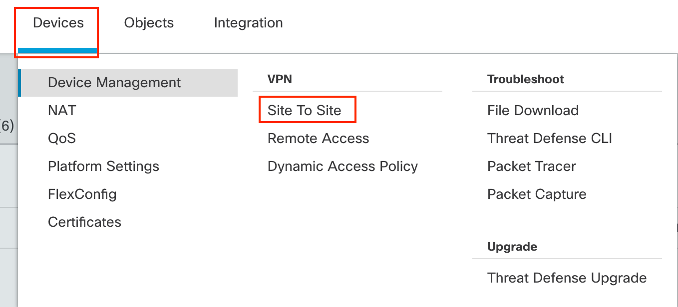
-
In the pop-up box, configure the following details:
-
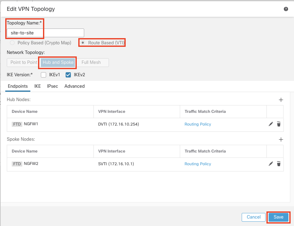
Topology Name: site-to-site
-
Select the Radio Button for "Route Based (VTI)"
-
Network Topology: Hub and Spoke
-
Click the + icon next to Hub Nodes
-
In the pop-up box, configure the following details:
-
Device: NGFW1
-
Dynamic Virtual Tunnel Interface: DVTI
-
Click on the dropdown of Advanced Settings.

In the Advanced Settings, check the box "Send Virtual Tunnel Interface IP to the peers"
-
-
Leave all other settings as default and click on OK
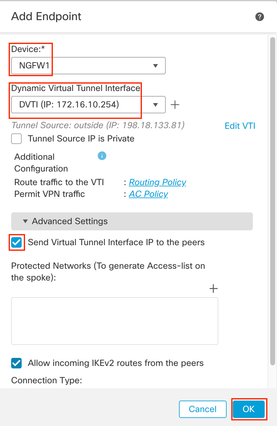
-
-
Click the + icon next to Spoke Nodes
-
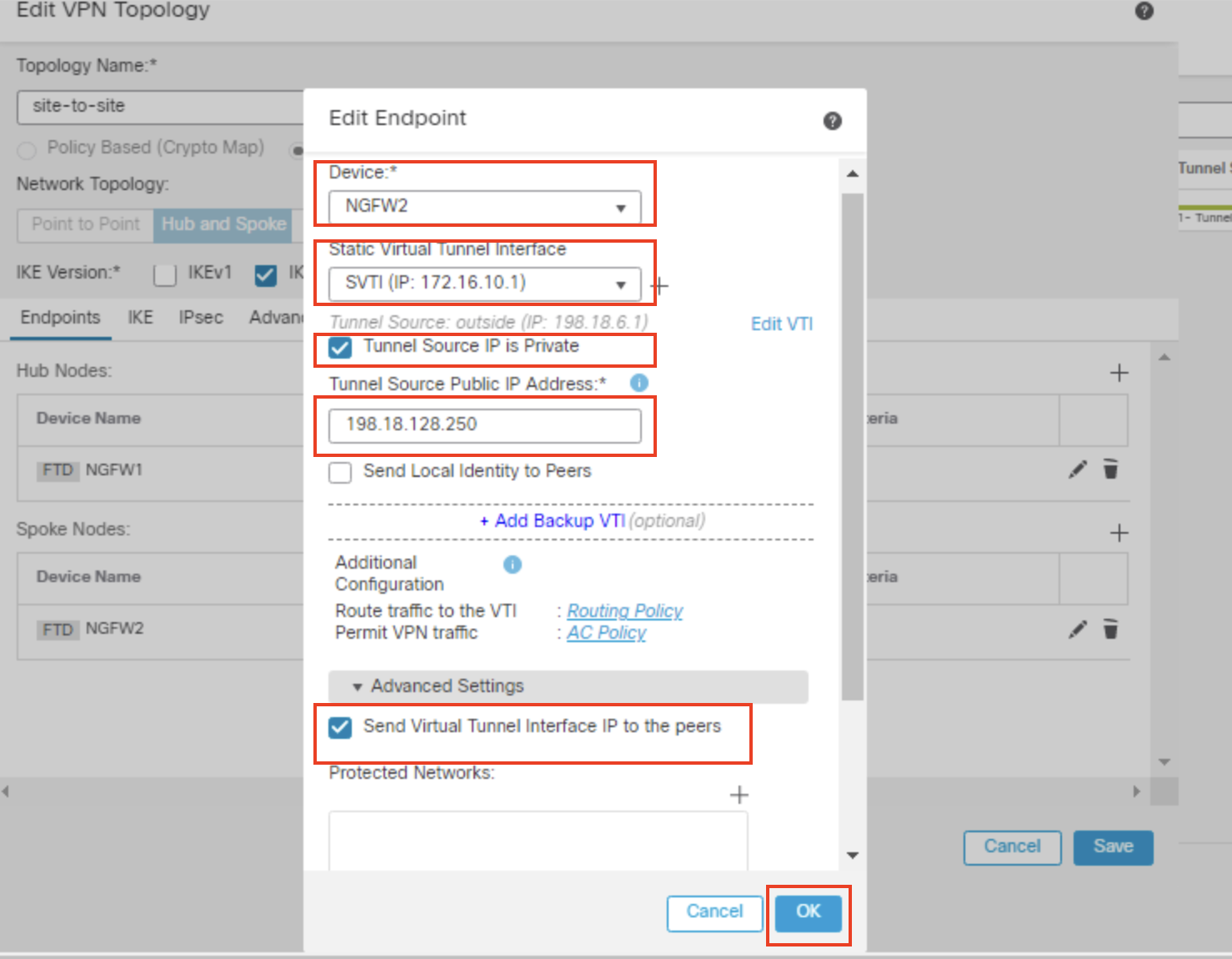
In the pop-up box, configure the following details:
-
Device: Select NGFW2 from the dropdown
-
Interface: SVTI
-
Select the checkbox for Tunnel Source IP is Private and enter 198.18.128.250 as Tunnel Source Public IP Address.
-
Click on the dropdown of Advanced Settings.

In the Advanced Settings, check the box "Send Virtual Tunnel Interface IP to the peers"
-
-
Leave all other settings as default and click OK
-
Here's what your final topology should look like. Click Save.
-
-
-
-
Task 4 - Configure EIGRP on NGFW2(Spoke)
-
Go to Device > Device Management and click the pencil (edit) icon next to NGFW2 which is the Spoke in our deployment.
-
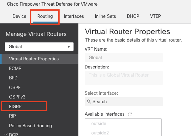
Click the Routing tab then click EIGRP on the left navigation pane.
-
Click the checkbox to enable EIGRP.
-
AS number: 150
-
Click on the + sign next to the Available Networks/Hosts
-
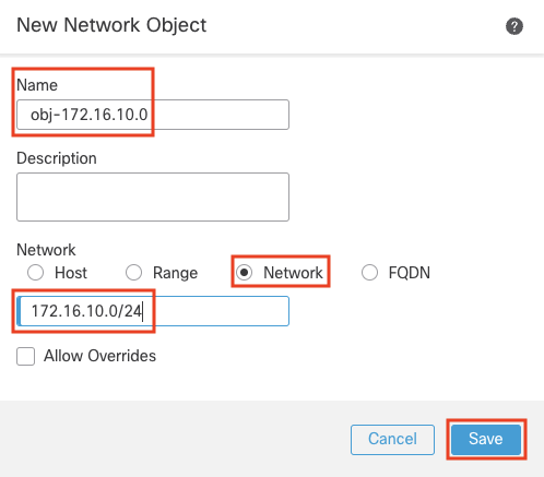
In the pop up box, Configure the following details
-
Name: obj-172.16.10.0
-
Select the Radio button next to Network
-
In the text box below enter 172.16.10.0/24
-
Click save
-
-
-
Click on the + sign next to the Available Networks/Hosts
-
In the pop up box, Configure the following details
-
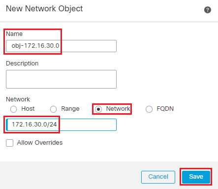
Name: obj-172.16.30.0
-
Select the Radio button next to Network
-
In the text box below enter 172.16.30.0/24
-
Click save
-
-
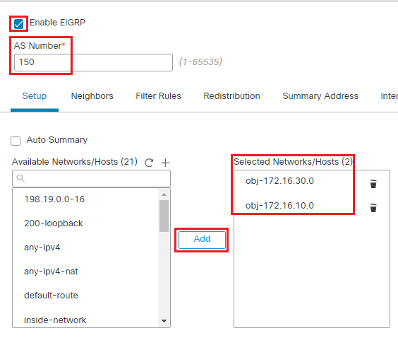
Select the objects created obj-172.16.10.0 and obj-172.16.30.0 and click on Add
-
-
Click on Save on the top right corner to save the configuration.
-
Task 5 - Configure EIGRP on NGFW1(Hub)
-
Go to Device > Device Management and click the pencil (edit) icon next to NGFW1 which is the Hub in our deployment.
-
Click the Routing tab then click EIGRP on the left navigation pane.

-
Click the checkbox to enable EIGRP.
-
AS number: 150
-
Click on the + icon next to the Available Networks/Hosts
-
In the pop-up box, Configure the following details
-
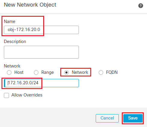
Name: obj-172.16.20.0
-
Select the Radio button next to Network
-
In the text box below enter 172.16.20.0/24
-
Click Save
-
-
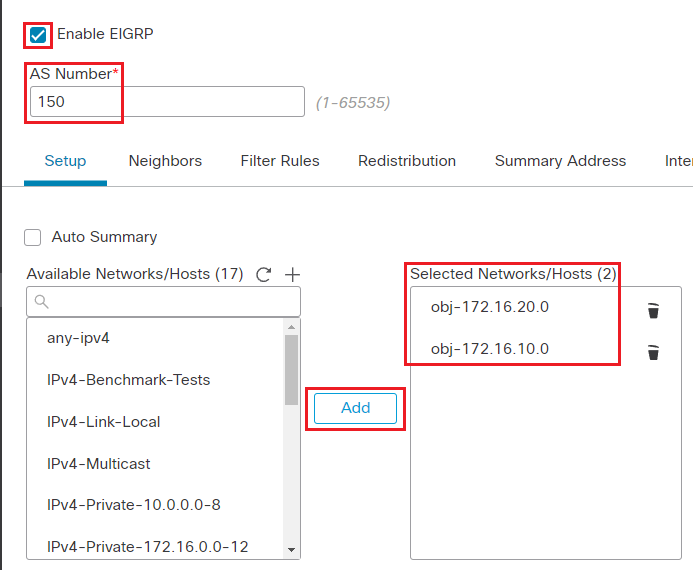
Select the objects created obj-172.16.10.0 and obj-172.16.20.0 and click Add.
-
Note:
Obj-172.16.10.0 is the same one created in Task 5 step 3.
-
-
Click Save on the top right corner of the webpage to save the configuration.
-
-
Task 6 - Deploy the configuration
- Click Deploy on the top-right corner.
- Click Deploy All
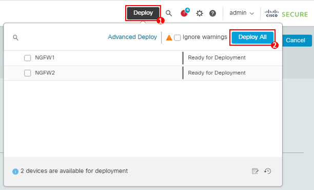
Note
- In the event you come across a 'Ignore warnings' checkbox during your deployment, please be sure to select it.
- Wait for the deployment to complete before proceeding further.
Task 7 - Explore the Site to Site Dashboard and Verify Tunnel Connection
- Navigate to Overview > Site to Site VPN.
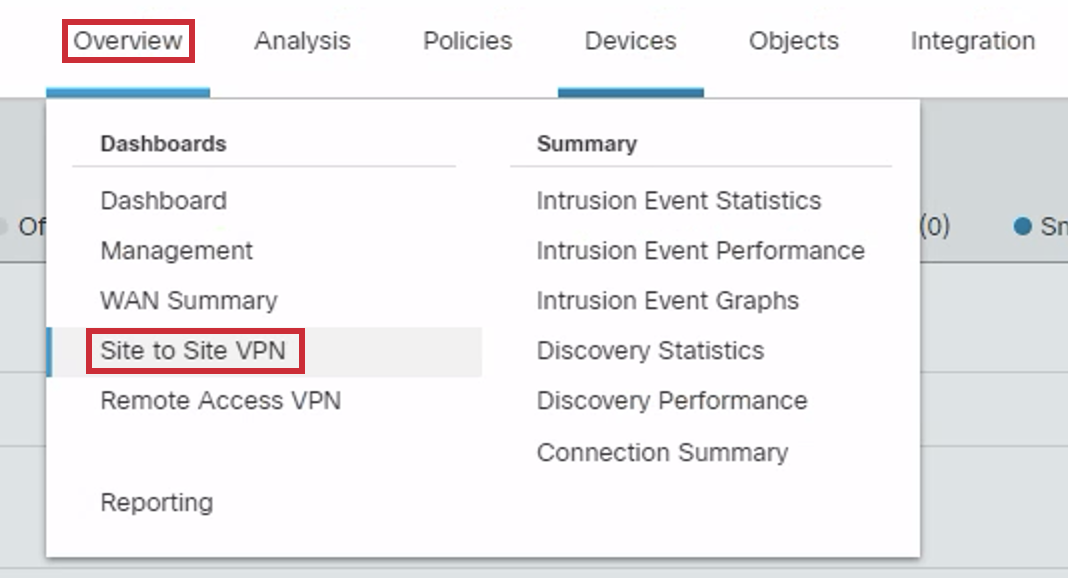
- Take a look at the active Site to Site VPN connection between NGFW1 and NGFW2.
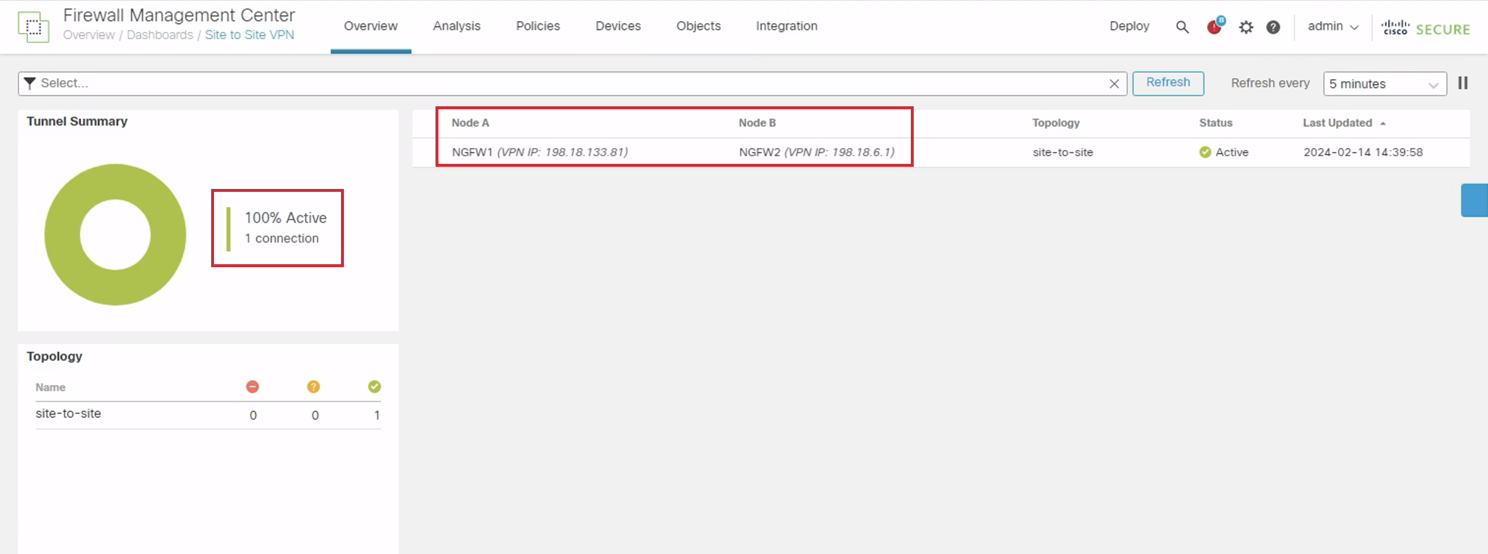
- Click on the eye icon next to the active connection as highlighted to view the full information.
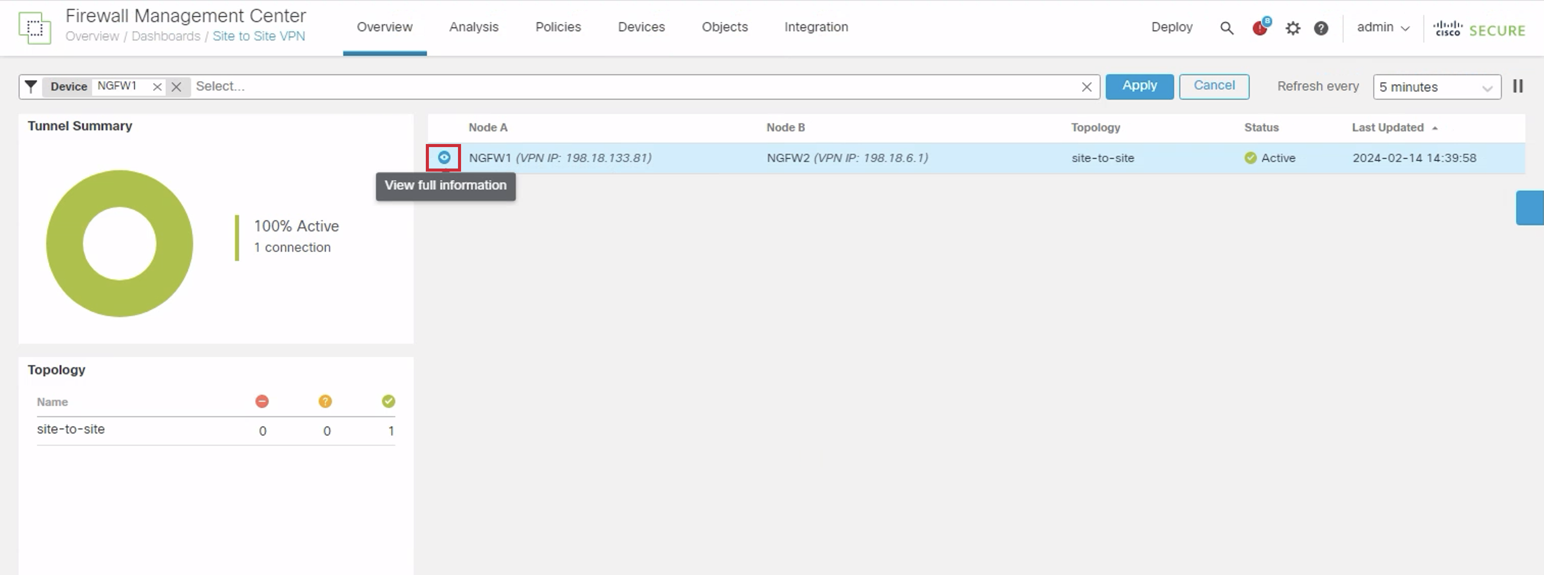
- In the General tab you will look at basic details of the connection.
Next switch to the CLI Details tab.
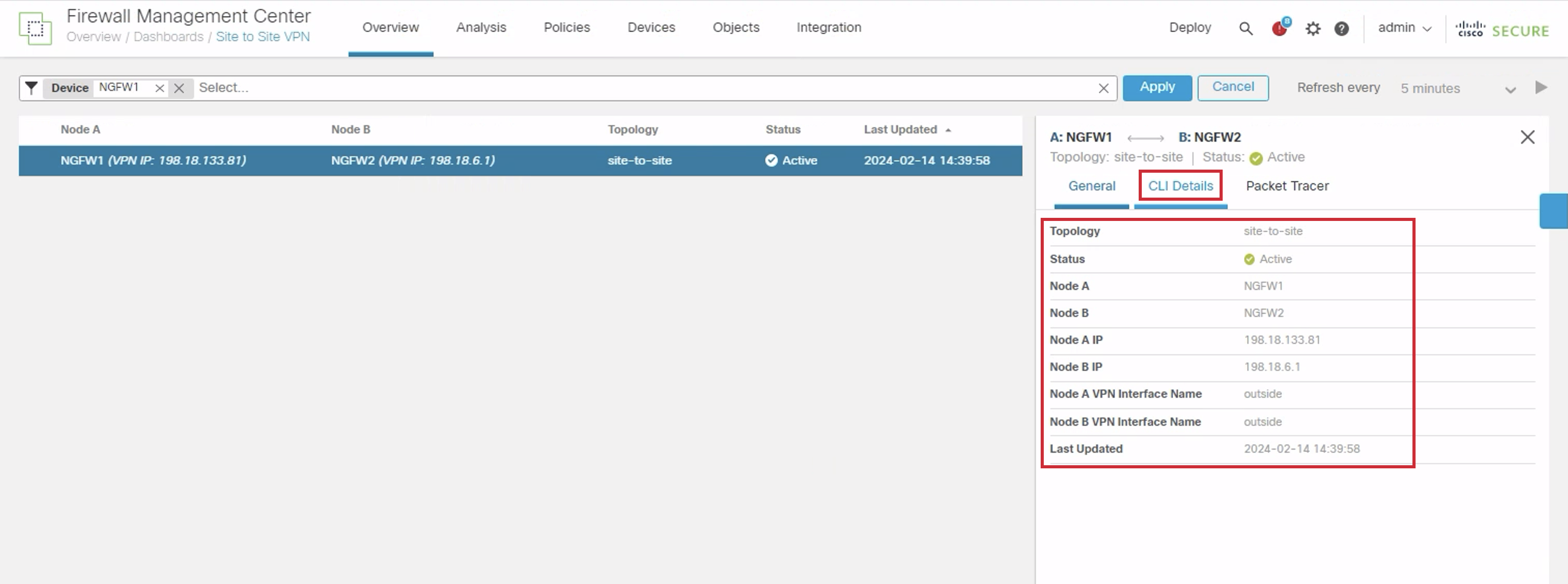
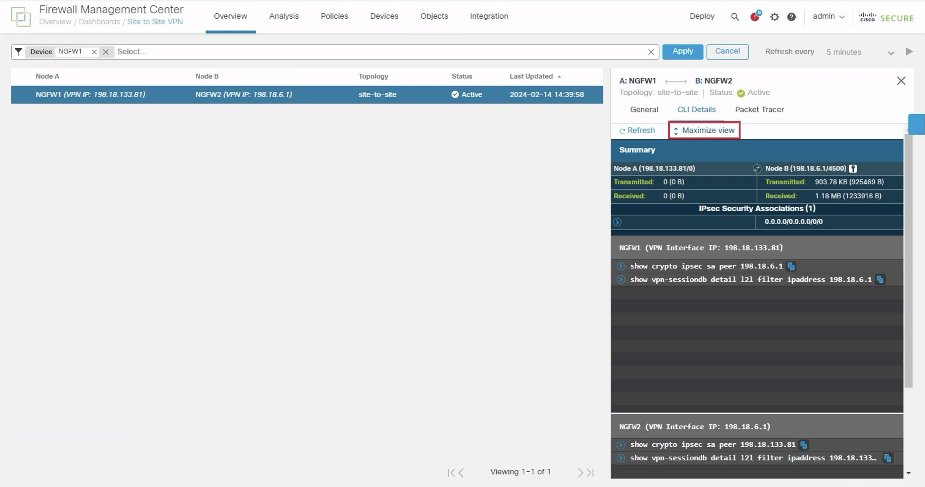
- Click on Maximize view for a better experience.
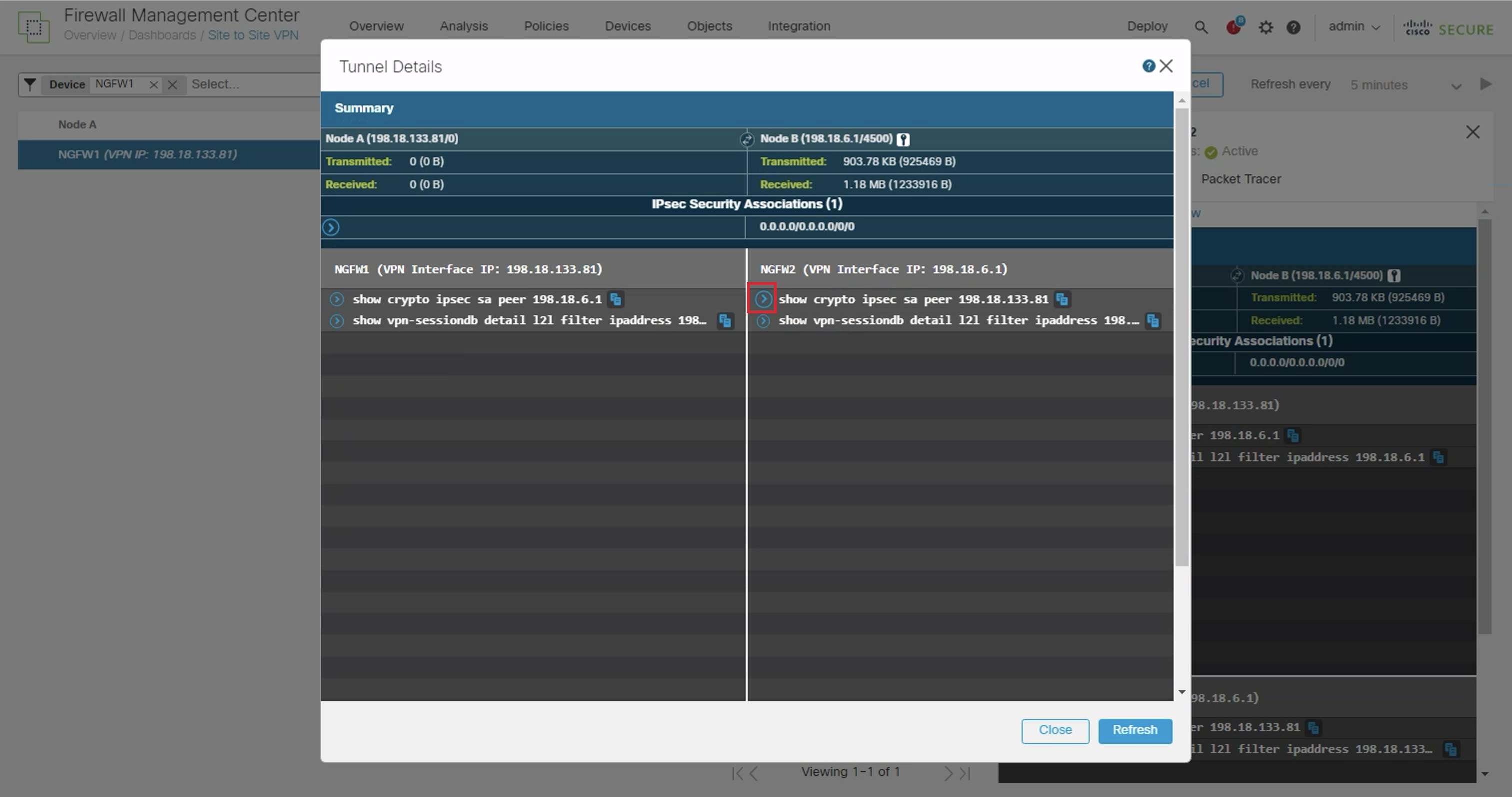
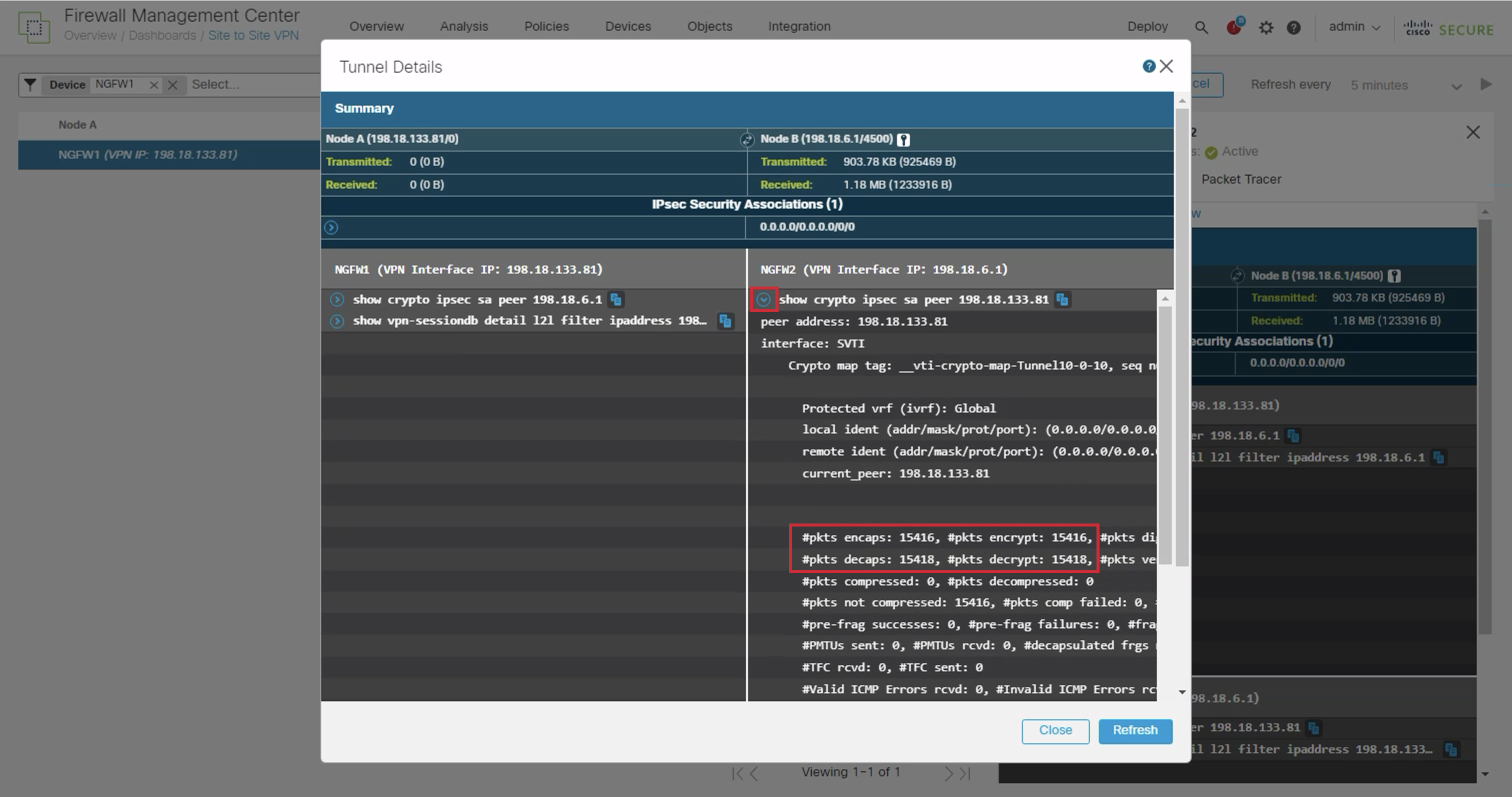
- In the NGFW2 section, click on the dropdown icon next to show crypto ipsec sa peer 198.18.133.81
- Here we can see the count of packets transmitted through the tunnel as indicated by the counters.
Proceed to the next step by closing the dropdown.
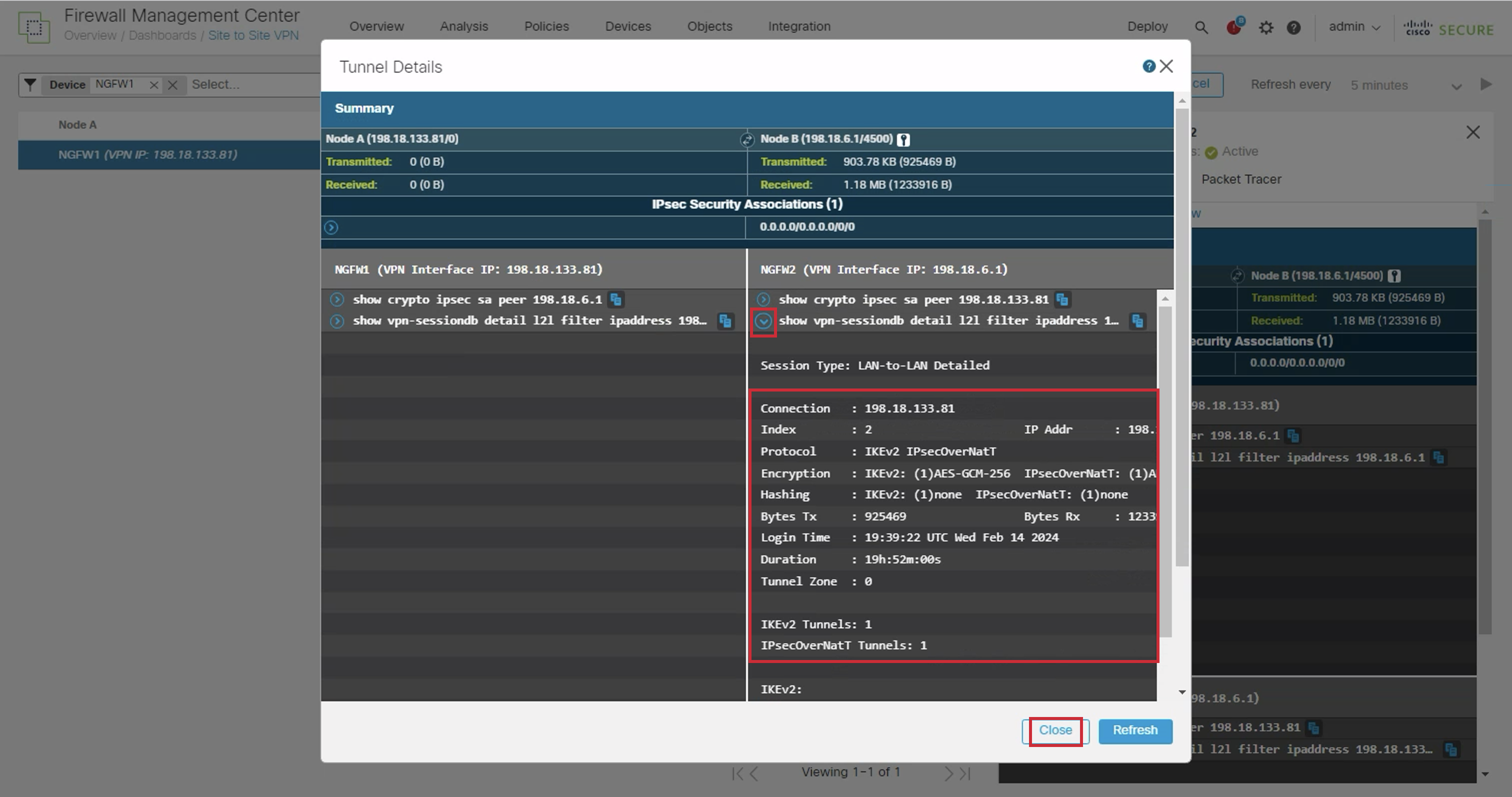
- Next click on the dropdown icon next to show vpn-sessiondb detail l2l filter ipaddress 198.18.6.1
Here we can see more detailed data related to the Site to Site VPN connection.
Proceed to the next step by pressing the Close button.
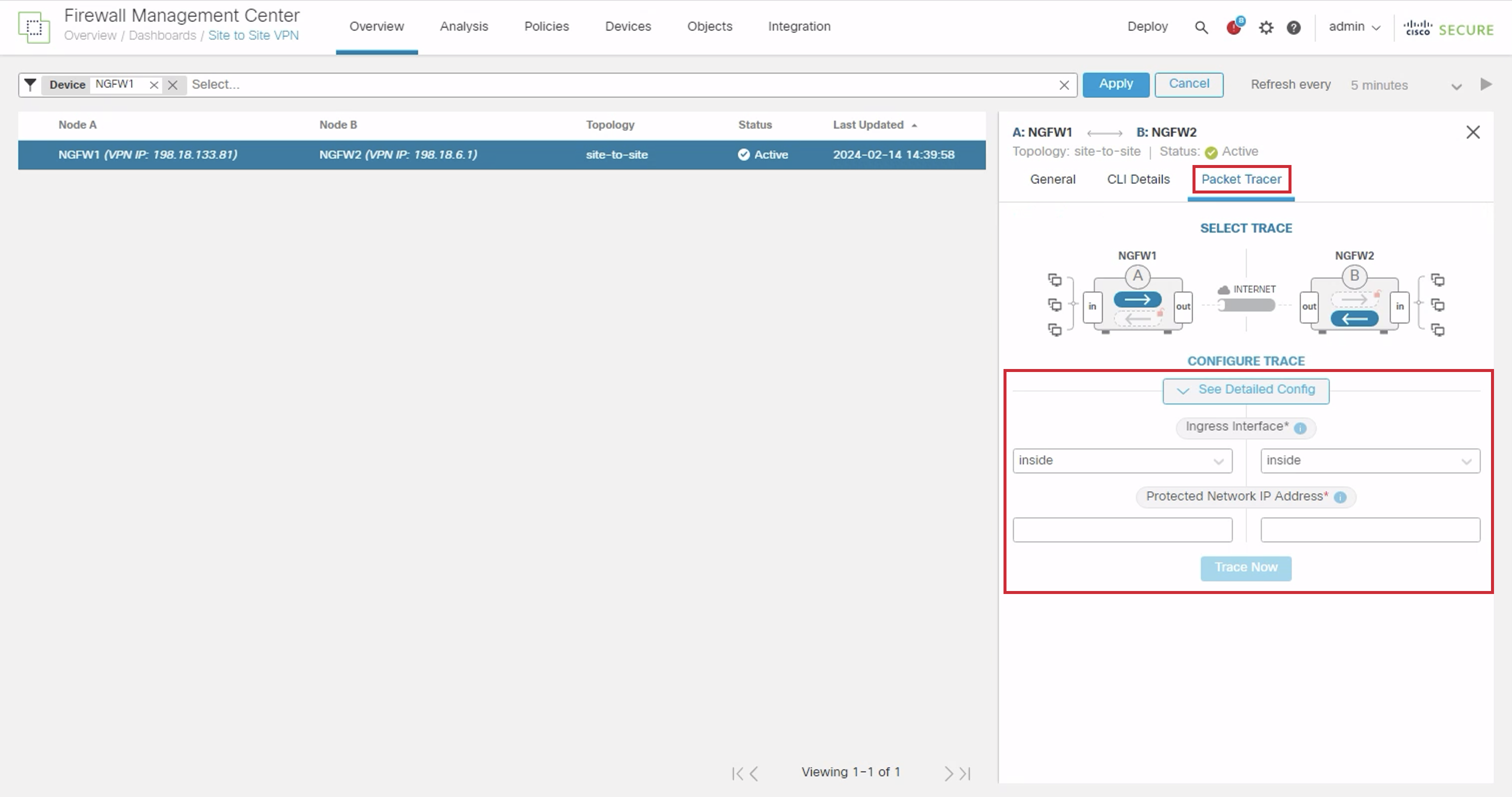
- Switch to the Packet Tracer to run packet-tracer to emulate traffic going through the tunnel.
Task 8 - Verify EIGRP Neighbours Sharing
-
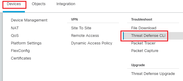
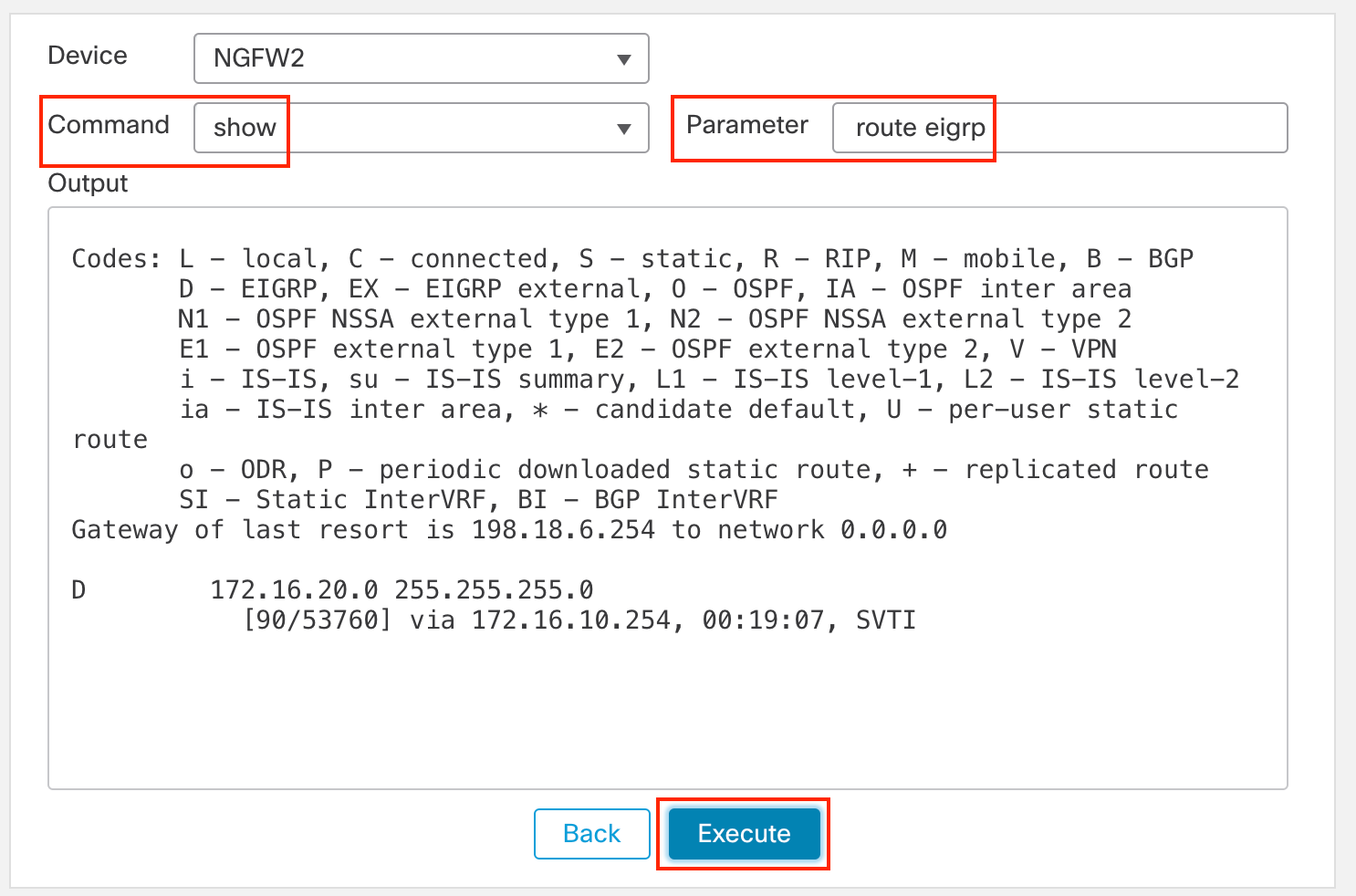
To confirm EIGRP neighbor connections and ensure mutual sharing, go to Device > Troubleshoot > Threat Defense CLI to run commands and verify the configuration.
-
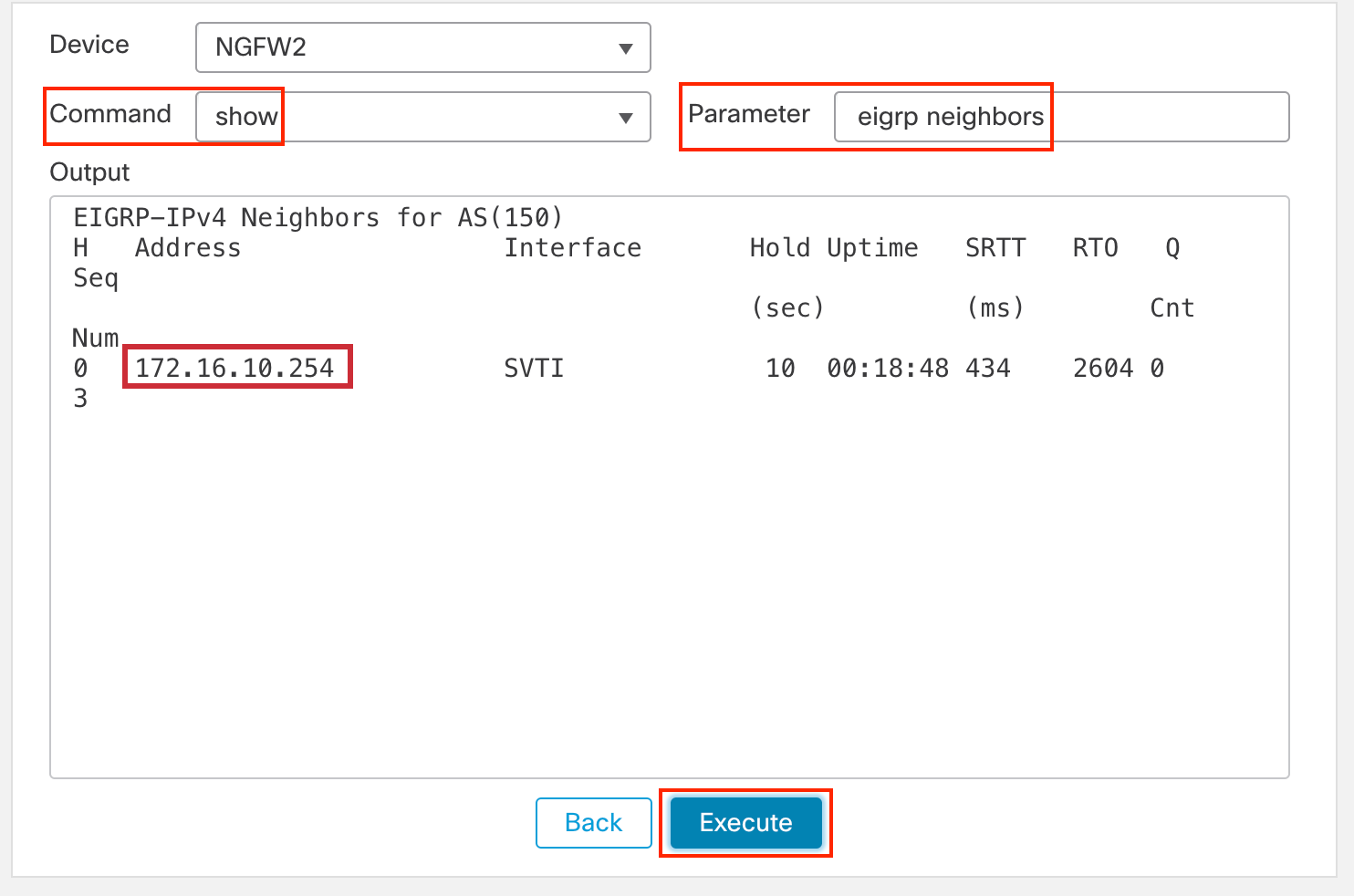
In the open window, change the Command to "show" and proceed with verification.
-
Now in the Parameter field, you can type any command.
-
In the Parameter field, type eigrp neighbors. This command provides visibility into the neighboring device connected at the opposite end of our tunnel, allowing us to identify and examine the peer relationship.
-
In the Parameter field, type route eigrp. As shown below, we gain visibility into the internal routes acquired from this hub side that were previously unknown letting us expand our network topology.
-
-
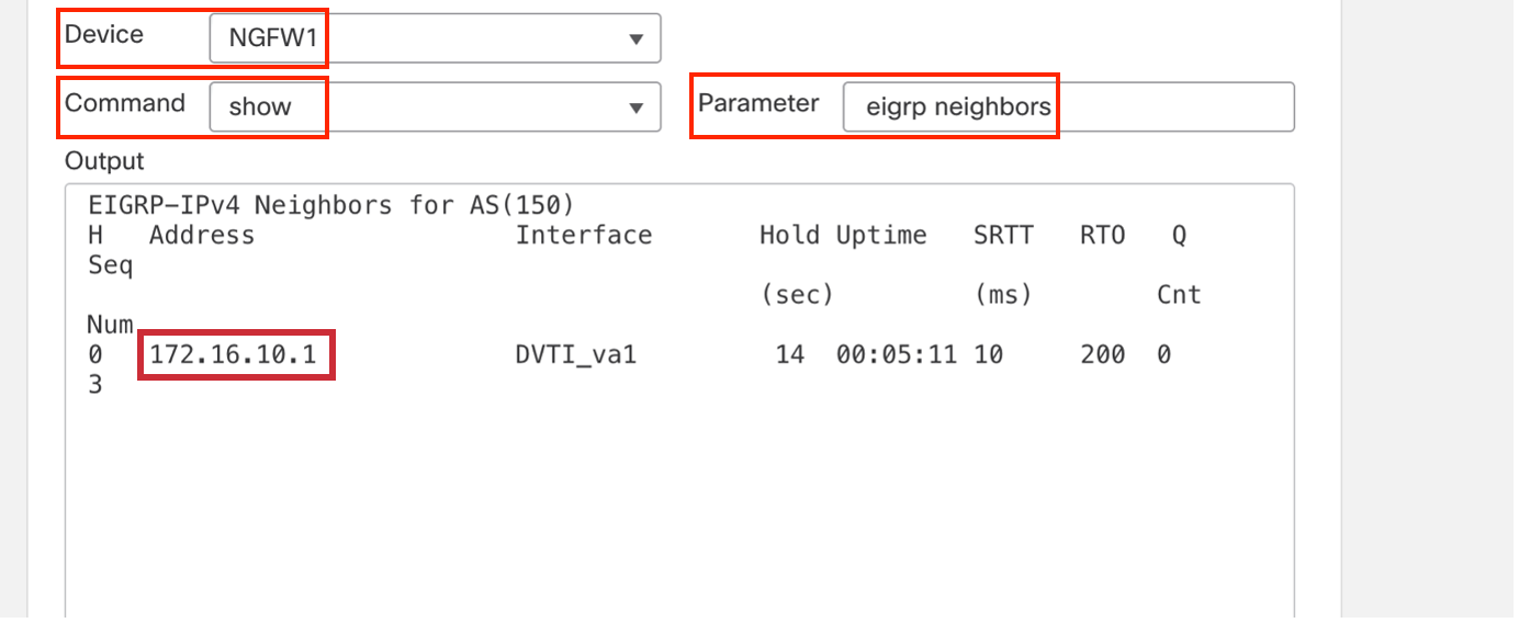
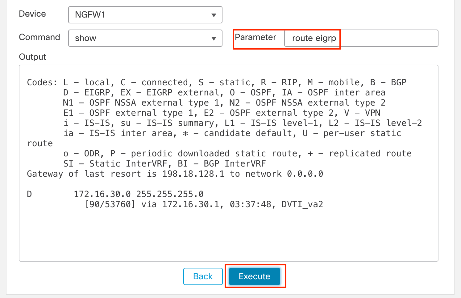
We can check the same with NGFW1.
-
Change the Device to NGFW1
-
In the Parameter, type eigrp neighbors.
-
In the Parameter, type route eigrp.
-
-
Conclusion
This concludes the Virtual Tunnel Interface (DVTI) based VPN tunnel lab on Cisco Secure Firewall.
What's Next
Updated about 1 year ago
