
Secure Firewall Reference Architecture for Spanned Mode Cluster with Inter-Site VXLAN
This reference architecture describes a four-node Cisco Secure Firewall 3140 cluster in spanned interface mode across two data centers. Each site has two Nexus 9332 leaves and two Nexus 9332 spines that also act as Multi-Site border gateways. VXLAN EVPN extends the protected and outside segments over a routed inter-site fabric. The firewall provides the protected servers’ gateways and inspects traffic routed between security zones.
The guide explains the device roles, VLAN and VNI mapping, OSPF and BGP adjacencies and inter-site cluster settings.
1. Introduction to the architecture
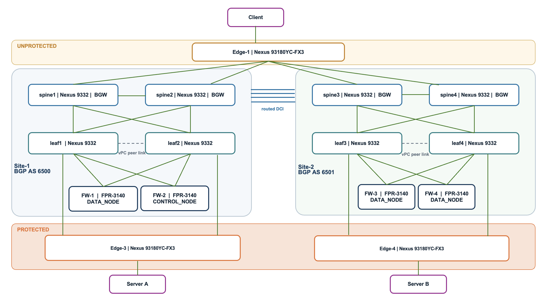
Figure 1. Physical topology
This architecture combines a Cisco Secure Firewall cluster with a Nexus VXLAN EVPN fabric across two sites. The firewalls provide security inspection and routing between security zones, while the switches provide redundant connectivity and extend the required network segments between sites.
Firewall cluster
Four Cisco Secure Firewall 3140 devices—two at each site—operate as one logical firewall cluster. The members share security configuration and interface addresses, providing additional processing capacity and redundancy.
One member is elected as the control node, coordinating cluster configuration and centralized functions. The other members operate as data nodes. All members, including the control node, can inspect traffic. Each connection has a connection owner responsible for its processing and state. The cluster control link (CCL) connects the members for health monitoring, state replication, and packet forwarding between members.
Leaf switches
Each site has two leaf switches operating as a virtual Port Channel (vPC) pair, providing redundant attachments for the firewalls and protected edge switches. The leaves connect both the firewall data interfaces and the dedicated CCL interfaces.
The leaves also act as VXLAN tunnel endpoints (VTEPs) and map local VLANs to VXLAN segments. Protected server VLANs remain Layer 2 on the leaves; their gateways reside on the firewall cluster. For the firewall’s outside network, the leaves provide the VLAN 30 routing interfaces and a shared HSRP next-hop address.
Spine switches and border gateways
Each leaf connects to both local spines, providing redundant fabric connectivity. The spines participate in the IP underlay and act as EVPN route reflectors, distributing overlay reachability information between switches.
In this architecture, the spines also act as Multi-Site border gateways (BGWs), connecting the two VXLAN fabrics across the routed data center interconnect. Each site’s BGW pair shares a Multi-Site VIP for inter-site VXLAN connectivity. The spines also provide routed connections to the unprotected edge switch.
Protected edge switches
Edge-3 at Site 1 and Edge-4 at Site 2 connect the protected servers to their local leaf pairs. They provide Layer 2 VLAN connectivity; the firewall cluster provides the protected servers’ default gateways and security enforcement.
Unprotected edge switch
Edge-1 is common to both sites and connects to all four spine/BGWs through routed links. It provides the gateway for the unprotected client network and its connectivity to the fabric.
Together, these components provide distinct roles for security enforcement, server attachment, fabric connectivity, and inter-site extension.
| Area | Design in the reference architecture |
|---|---|
| Firewall cluster | Four FPR-3140 nodes, two per site; site IDs 1 and 2; spanned interface mode; site redundancy and director localization. |
| Data interfaces | Port-channel10 with VLAN 10 inside_10, VLAN 20 inside_20, and VLAN 30 outside. |
| Cluster control | Firewall Port-channel48; switch VLAN 99 |
| Fabric routing | Per-site OSPF underlay; local iBGP EVPN; AS 6500 at Site 1 and AS 6501 at Site 2. Spines combine transit, route-reflection, BGW, and WAN attachment roles. |
| Inter-site transport | Four routed /30 DCI links in full mesh with IPv4 eBGP. Separate EVPN eBGP sessions use the BGW Loopback0 addresses. |
Each site has a local vPC leaf pair, two spine/BGWs, and two firewall members. A vPC pair presents redundant switch connections to attached devices. The firewall’s split-spanned data EtherChannel uses local switch-side LACP bundles at each site. LACP combines physical member links into a logical port-channel.
1.1. Components and roles
| Component | Site 1 | Site 2 | Role |
|---|---|---|---|
| Firewall members | FW-1 and FW-2 | FTD 3 and FTD 4 | FPR-3140 cluster members. Site IDs 1 and 2. |
| Leaf vPC pair | leaf1 and leaf2 | leaf3 and leaf4 | Attach firewall data and CCL interfaces and protected edges. Provide VLAN-to-VNI mapping, local VTEPs, and the outside VLAN 30 HSRP gateway. |
| Spine and BGW pair | spine1 and spine2 AS 6500 | spine3 and spine4 AS 6501 | Carry local underlay traffic, reflect EVPN routes, terminate Multi-Site VXLAN, and connect the unprotected edge. |
| Unprotected edge | Edge-1 is common to both sites | Edge-1 is common to both sites | VLAN 101 gateway and four routed OSPF connections to all the four spines. |
| Protected edge | Edge-3 | Edge-4 | Layer 2 server attachments. VLAN 10 and VLAN 20 reach the firewall through the leaves. |
1.2. Underlay and overlay
The underlay is the IP network that transports VXLAN-encapsulated traffic. OSPF provides reachability within each site, while IPv4 BGP exchanges transport routes over the data center interconnect (DCI) between sites.
The overlay consists of the logical Ethernet segments and routing contexts carried over that IP network. VXLAN encapsulates an Ethernet frame inside a UDP/IP packet. A VXLAN tunnel endpoint (VTEP) adds or removes this encapsulation, and a VXLAN network identifier (VNI) identifies the bridged segment or routing context. The switch’s nve1 interface represents its VXLAN tunnel function.
VXLAN EVPN combines two complementary functions: VXLAN carries the actual traffic, while Ethernet VPN (EVPN) distributes the reachability information used to forward it. EVPN uses BGP to advertise MAC addresses, IP addresses, and network prefixes between participating switches. These advertisements tell switches which tunnel endpoint or border gateway provides reachability to a destination. Together, VXLAN and EVPN allow logical networks to extend across an IP fabric, with EVPN providing the control plane and VXLAN providing the data plane.
In this lab, the spines also provide border gateway (BGW) and WAN attachment functions. A larger design may use dedicated border leaf and BGW switches for WAN and DCI connectivity, while the local spines provide fabric transit and EVPN route reflection.
2. Segment and VNI map
A VLAN identifies a local Ethernet segment. A Layer 2 VNI carries that segment through VXLAN. A Layer 3 VNI identifies a VRF routing context. A VRF is a separate routing table. The map helps trace each segment without confusing server gateways, transit gateways, and VXLAN transport addresses.
| Purpose | VLAN | VNI | Gateway or context | Forwarding role |
|---|---|---|---|---|
| Protected inside_10 | 10 | 30002 L2 | FTD 10.10.0.1/16 | Layer 2 on protected edges and leaves; the firewall is the server gateway and routes between VLAN 10 and VLAN 20. |
| Protected inside_20 | 20 | 30001 L2 | FTD 10.20.0.1/16 | Layer 2 on protected edges and leaves; the firewall is the server gateway and routes between VLAN 10 and VLAN 20. |
| Firewall outside | 30 | 30003 L2 | FTD 10.30.0.1/24; HSRP 10.30.0.2 | Extended outside transit. Leaf SVIs .254, .253, .251, and .252 establish OSPF with the firewall. |
| Cluster Control Link | 99 | 30000 L2 | 99.99.99.0/27; node addresses .1–.4 | Dedicated cluster broadcast domain in the supplied VXLAN configuration. |
| Unprotected VRF | 2001 | 50001 L3 | VRF unprotected | SVI uses ip forward with no gateway IP. Outside routing uses the separate VLAN 30 SVI. |
| Unprotected hosts | 101 | No VXLAN VNI | Edge-1 10.101.0.1/16 | WAN/test-host attachment on Edge-1, routed toward all four BGWs. |
The presence of a VLAN, VRF, or VNI in a configuration identifies a configured object. Its role in the active traffic path must also be read from the interfaces, routing, and operational evidence. VLANs 10 and 20 have no server-gateway SVI on the leaves. The ip forward SVIs for VLAN 2001 support the L3 VNI function rather than host default gateways.
3. Firewall cluster and inter site requirements
FW-1 and FW-2 use site ID 1; FW-3 and FW-4 use site ID 2. The control node is an elected role, not a permanent topology identity.
| Firewall interface | Addressing | Architecture role |
|---|---|---|
| Port-channel10.10 | 10.10.0.1/16 | Protected VLAN 10 gateway, global MAC, and per-site MAC/IP settings. |
| Port-channel10.20 | 10.20.0.1/16 | Protected VLAN 20 gateway, global MAC, and per-site MAC/IP settings. |
| Port-channel10.30 | 10.30.0.1/24 | Outside transit; OSPF neighbors are the four leaf VLAN 30 SVIs. Default route uses HSRP 10.30.0.2. |
| Port-channel48 | 99.99.99.1–.4/27 | Dedicated firewall CCL interface. Carries coordination, state replication, and forwarding to another connection owner. |
3.1. Site IDs and redundancy
| Member | Site ID | Priority |
|---|---|---|
| FW-1 | 1 | 1 |
| FW-2 | 1 | 2 |
| FW-3 | 2 | 3 |
| FW-4 | 2 | 4 |
FW-1# show run
cluster group 3140-Cluster
 site-redundancy
 director-localization
NOTE: The configuration snippets shown in this document are configuration excerpts.
Director localization supports a director and backup role at the connection owner’s site for eligible flows. (Exceptions include NAT/PAT connections, SCTP-inspected traffic, and fragment-owner queries.) As a director holds the session information, session ownership queries do not have to cross a site and can stay local. Site redundancy provides another-site backup when the existing backup is at the owner’s site, so if a site fails, the session information is not lost. The surrounding network’s routing and load balancing determine which firewall receives traffic, and some connections may still require cross-site forwarding or global-director queries.
3.2. Global and site-specific MAC and IP addresses
The firewall’s global interface IP remains the address used to reach that interface. For VLANs 10 and 20, it is the server gateway. The cluster also uses one site-specific MAC/IP pair per site and per interface for its site-specific ARP behavior and outgoing Layer 2 identity. These settings do not automatically rewrite the source IP of forwarded server traffic.
Global addresses: how traffic reaches the firewall
Each firewall data interface has a global IP address shared by the cluster. For example, servers in VLAN 10 use 10.10.0.1 as their default gateway, regardless of their site.
The interface also has a global MAC address. When a server uses ARP to find the MAC address of its gateway, the firewall responds with this global MAC. The server then uses that MAC as the destination of Ethernet frames sent to the firewall.
In this lab, the global MAC is cced.4dd4.5000 on VLANs 10, 20, and 30. The VLAN separates these interfaces even though they use the same MAC.
FW-1# show run
interface Port-channel10.10
 mac-address cced.4dd4.5000
interface Port-channel10.20
 mac-address cced.4dd4.5000
interface Port-channel10.30
 mac-address cced.4dd4.5000
Site-specific addresses: how the firewall sends traffic
Each interface also has a site-specific MAC and IP pair for each site. Members use the pair corresponding to their configured site ID; these are per-site identities, rather than separate identities for every firewall member.
Outgoing Ethernet frames use the site-specific source MAC. This gives switches a distinct MAC to learn for each site and helps prevent MAC flapping—the same MAC repeatedly appearing through different local and remote attachments.
The site-specific IP is used with the site-specific MAC when the firewall performs ARP to resolve a directly connected destination or next hop.
FW-1# show run
interface Port-channel10.10
 mac-address cced.4dd4.1011 site-id 1 site-ip 10.10.0.5
 mac-address cced.4dd4.1012 site-id 2 site-ip 10.10.0.6
interface Port-channel10.20
 mac-address cced.4dd4.2011 site-id 1 site-ip 10.20.0.5
 mac-address cced.4dd4.2012 site-id 2 site-ip 10.20.0.6
interface Port-channel10.30
 mac-address cced.4dd4.3011 site-id 1 site-ip 10.30.0.5
 mac-address cced.4dd4.3012 site-id 2 site-ip 10.30.0.6
Servers continue to use the global gateway IP. The .5 and .6 addresses do not replace their gateways or automatically replace the source IP of forwarded server packets.
Example: A Site-1 server sends traffic outside
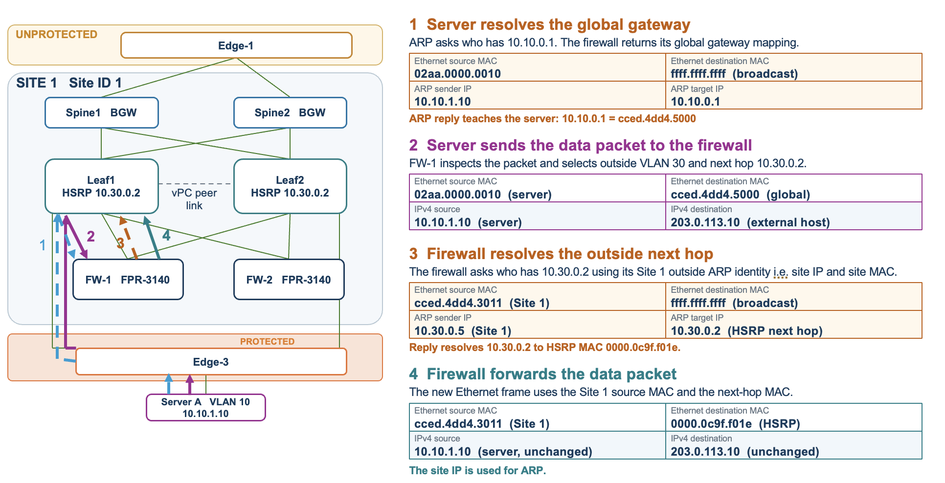
Figure 2. Global and site-specific MAC flows
This example follows a VLAN 10 server at Site 1 with IP address 10.10.1.10 accessing an external destination, 203.0.113.10. These host addresses are illustrative. Assume the ARP entries have not yet been learned and no NAT applies.
-
The server resolves its gateway’s MAC address
The server broadcasts an ARP request asking, “Who has 10.10.0.1?” The firewall replies with its global gateway mapping:
Gateway IP:   10.10.0.1
Gateway MAC:  cced.4dd4.5000
The server saves this mapping in its ARP table. It continues to use the global IP as its gateway.
-
The server sends its data packet to the firewall
The server places the IP packet inside an Ethernet frame addressed to the firewall’s global MAC:
Ethernet source MAC:       Server MAC
Ethernet destination MAC:  cced.4dd4.5000
IP source:                10.10.1.10
IP destination:           203.0.113.10
The destination MAC delivers the frame to the firewall, while the destination IP identifies the external host. A local firewall receives and inspects the packet, then selects its outside interface on VLAN 30 and next hop 10.30.0.2.
-
The firewall resolves the outside next hop’s MAC address
The firewall broadcasts an ARP request on VLAN 30 using its Site 1 outside MAC/IP pair:
ARP sender IP:   10.30.0.5
ARP sender MAC:  cced.4dd4.3011
ARP target IP:   10.30.0.2
In words: “Who has 10.30.0.2? Tell 10.30.0.5.”
The next hop replies with its MAC address. Here, 10.30.0.5 identifies the firewall in the ARP exchange; it does not replace the server’s source IP.
-
The firewall forwards the data packet
The firewall creates a new Ethernet frame using its site-specific source MAC and the resolved next-hop MAC:
Ethernet source MAC:       cced.4dd4.3011
Ethernet destination MAC:  Next-hop MAC
IP source:                10.10.1.10
IP destination:           203.0.113.10
The Ethernet addresses change as the firewall routes the packet. The server’s source IP and external destination IP remain unchanged in this example.
The global MAC allows traffic to reach the cluster. The site-specific MAC identifies the site sending the outgoing frame. Configuring a site-specific IP alongside that MAC is recommended because it provides a distinct IP–MAC pair for each site’s ARP requests, separate from the shared global gateway identity.
3.3. EVPN filtering of the global firewall MAC
The BGWs filter remote EVPN advertisements containing the global firewall MAC so each site retains its local firewall gateway attachment. The firewall cluster uses the same global MAC address (cced.4dd4.5000) at both sites. Without filtering, EVPN could advertise this MAC across sites and provide a remote path to the firewall, potentially sending traffic across the inter-site link even when local firewall members are available. To keep gateway access local, the spine/BGWs reject EVPN routes for the global MAC received from remote-site neighbors while retaining local reachability. Site-specific MAC routes remain permitted, allowing each site’s outgoing firewall identity to be learned separately.
spine1# show run
mac-list Global-mac-filter seq 15 permit cced.4dd4.5000 ffff.ffff.ffff
route-map Global-mac-filter deny 10
  match mac-list Global-mac-filter
route-map Global-mac-filter permit 20
router bgp 6500
  neighbor 10.12.0.1
    address-family l2vpn evpn
      route-map Global-mac-filter in
  neighbor 10.12.0.3
    address-family l2vpn evpn
      route-map Global-mac-filter in
The policy is applied on every BGW to its remote-site EVPN neighbors. Spine-1 and Spine-2 use remote peers 10.12.0.1 and 10.12.0.3; Spine-3 and Spine-4 use 10.2.0.1 and 10.2.0.3. The site-specific firewall MAC advertisements remain permitted.
3.4. HSRP localization on the outside VLAN
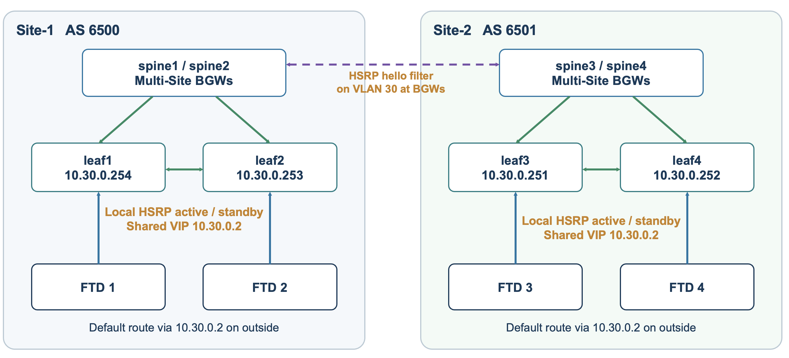
Figure 3. HSRP
HSRP provides a virtual next-hop IP shared by the two leaves at each site. All four leaves use VIP 10.30.0.2 on VLAN 30, with a local active/standby pair in each site. The BGWs filter HSRP hellos on the extended VLAN so the two sites do not form one four-leaf HSRP election.
spine1# show run
ip access-list hsrp-hello-filter
  10 permit udp any 224.0.0.2/32 eq 1985
  20 permit udp any 224.0.0.102/32 eq 1985
ip access-list permit-all
  10 permit ip any any
vlan access-map hsrp-hello-filter 10
  match ip address hsrp-hello-filter
  action drop
vlan access-map hsrp-hello-filter 20
  match ip address permit-all
  action forward
vlan filter hsrp-hello-filter vlan-list 30
The ACL permit entries identify the packets to match. The access-map action drop performs the filtering. This packet filter is separate from the EVPN global MAC route filter.
3.5. Symmetric port channel hashing
leaf1# show run
port-channel load-balance src-dst ip-l4port symmetric
Symmetric hashing uses the source and destination IP addresses and transport ports consistently in both directions. It helps reduce unnecessary forwarding between firewall members. All the packets belonging to a session are sent to the same firewall. ECMP routing, connection ownership, and failures can still cause packets to reach another member or site.
3.6. CCL MTU
The CCL must accommodate a complete forwarded data packet plus 100 bytes of cluster overhead. VXLAN transport requires additional headroom—commonly budgeted as 54 bytes, giving approximately 154 bytes of combined cluster and VXLAN overhead. Hence, MTU on the CCL is 9000+154=9154 bytes.
FW-1#show run
mtu inside_10 9000
mtu inside_20 9000
mtu outside 9000
mtu cluster 9154
4. OSPF adjacencies
OSPF is used for the local fabric underlay, for firewall-facing routing on VLAN 30, and for the routed connections from the common unprotected edge to the BGWs. The UNDERLAY process is confined to each fabric site. Firewall-facing VLAN 30 is extended between sites, and Edge-1 has physical routed links to both sites.
4.1. Leaf and spine underlay
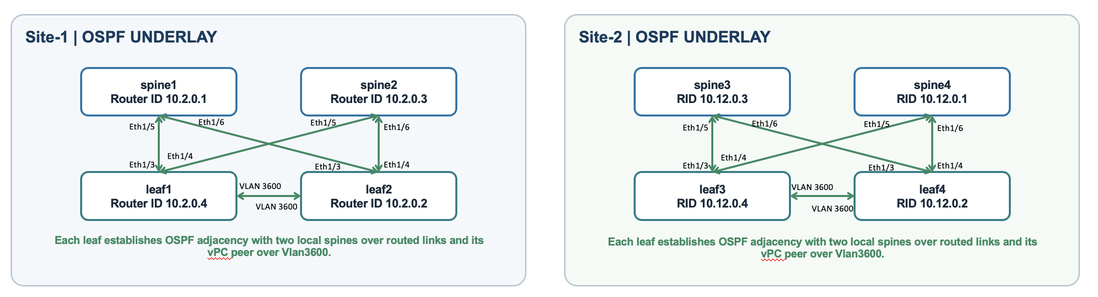
Figure 4. Leaf and Spine OSPF adjacency
Each leaf forms an OSPF adjacency with its two local spines over routed interfaces. It also forms an adjacency with its local vPC peer using the VLAN 3600 SVI across the peer link. An SVI is the routed interface for a VLAN. VLAN 3600 provides an IP connection between the local leaf peers; it is not a server gateway or an inter-site stretched segment.
leaf1# show ip ospf neighbors
OSPF Process ID UNDERLAY VRF default
Total number of neighbors: 3
Neighbor ID     State       Address       Interface
10.2.0.2        FULL/ -     10.4.0.2      Vlan3600
10.2.0.1        FULL/ -     10.4.0.14     Eth1/3
10.2.0.3        FULL/ -     10.4.0.18     Eth1/4

leaf3# show ip ospf neighbors
10.12.0.2       FULL/ -     10.14.0.2     Vlan3600
10.12.0.3       FULL/ -     10.14.0.14    Eth1/3
10.12.0.1       FULL/ -     10.14.0.10    Eth1/4
The three FULL entries identify the two local spines and the local peer leaf. In Site 1, Leaf-1’s router ID is 10.2.0.4 and Leaf-2’s is 10.2.0.2. Site-2 leaf router IDs are 10.12.0.4 and 10.12.0.2. A router ID identifies the OSPF speaker; the Address column identifies its interface on that adjacency.
4.2. Firewall and leaf neighbors
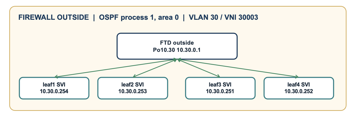
Figure 5. Firewall and leaf OSPF adjacency
In spanned interface mode, the control node participates in dynamic routing for the cluster. The logical outside interface forms OSPF adjacencies with the four leaf VLAN 30 SVIs. The server-side VLAN 10 and VLAN 20 interfaces advertise their networks; they do not have protected-edge OSPF neighbors in this lab.
FW-2#cluster exec show ospf neighbor
Neighbor ID  State          Address       Interface
1.1.1.1      FULL/DROTHER   10.30.0.254   outside
1.1.1.2      FULL/DROTHER   10.30.0.253   outside
2.2.2.1      FULL/DROTHER   10.30.0.251   outside
2.2.2.2      FULL/BDR       10.30.0.252   outside
FW-2#router ospf 1
 network 10.10.0.1 255.255.255.255 area 0
 network 10.20.0.1 255.255.255.255 area 0
 network 10.30.0.1 255.255.255.255 area 0
 log-adj-changes
route outside 0.0.0.0 0.0.0.0 10.30.0.2 1
The default route uses the outside HSRP next hop. The inside network statements allow OSPF to advertise the connected protected prefixes. The firewall uses network 10.10.0.1 255.255.255.255 area 0 and network 10.20.0.1 255.255.255.255 area 0 to include the protected interfaces in OSPF and advertise their connected networks to the leaves through VLAN 30 as intra-area routes. This achieves the network-advertisement purpose intended. No OSPF adjacencies form on VLANs 10 and 20 because the protected switches operate only at Layer 2. However, these commands do not suppress OSPF hellos or make the interfaces passive. With OSPFv3, passive-interface can be used to explicitly suppress hellos while retaining advertisement of the protected prefixes through the active OSPF interfaces.
4.3. Unprotected edge and BGW neighbors
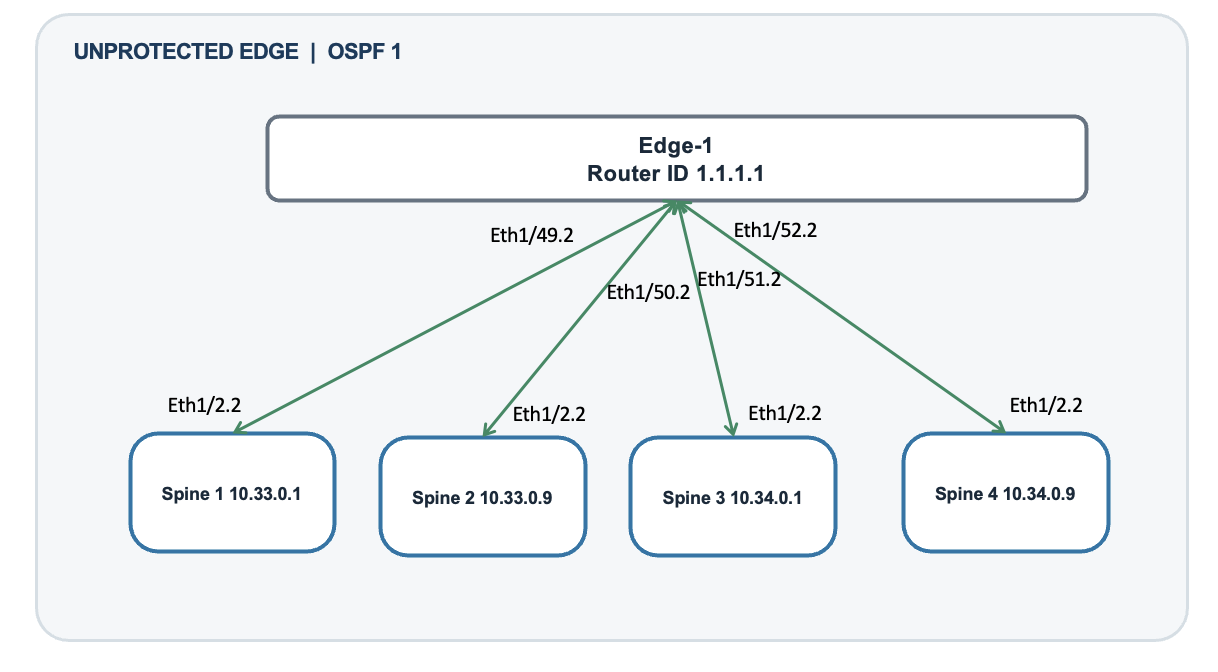
Figure 6. Edge and spine OSPF adjacency
Edge1# show ip ospf neighbors
OSPF Process ID 1 VRF default
Total number of neighbors: 4
Neighbor ID   State       Address       Interface
10.33.0.1     FULL/ -     10.33.0.1     Eth1/49.2
10.33.0.9     FULL/ -      10.33.0.9     Eth1/50.2
10.34.0.1     FULL/ -     10.34.0.1     Eth1/51.2
10.34.0.9     FULL/ -     10.34.0.9     Eth1/52.2
Edge-1 has four FULL neighbors: Spine-1 at 10.33.0.1, Spine-2 at 10.33.0.9, Spine-3 at 10.34.0.1, and Spine-4 at 10.34.0.9. Its interfaces Ethernet1/49.2 through Ethernet1/52.2 are routed subinterfaces using dot1q tag 2. The tag does not create a protected-server VLAN extension.
5. BGP adjacencies and VXLAN forwarding
BGP carries IPv4 transport routes and EVPN overlay routes. IPv4 transport routes make remote BGW loopbacks and tunnel addresses reachable. EVPN identifies the MAC, IP, and prefix destinations carried through the overlay. These are separate address families and neighbor relationships.
5.1. BGP inside each site
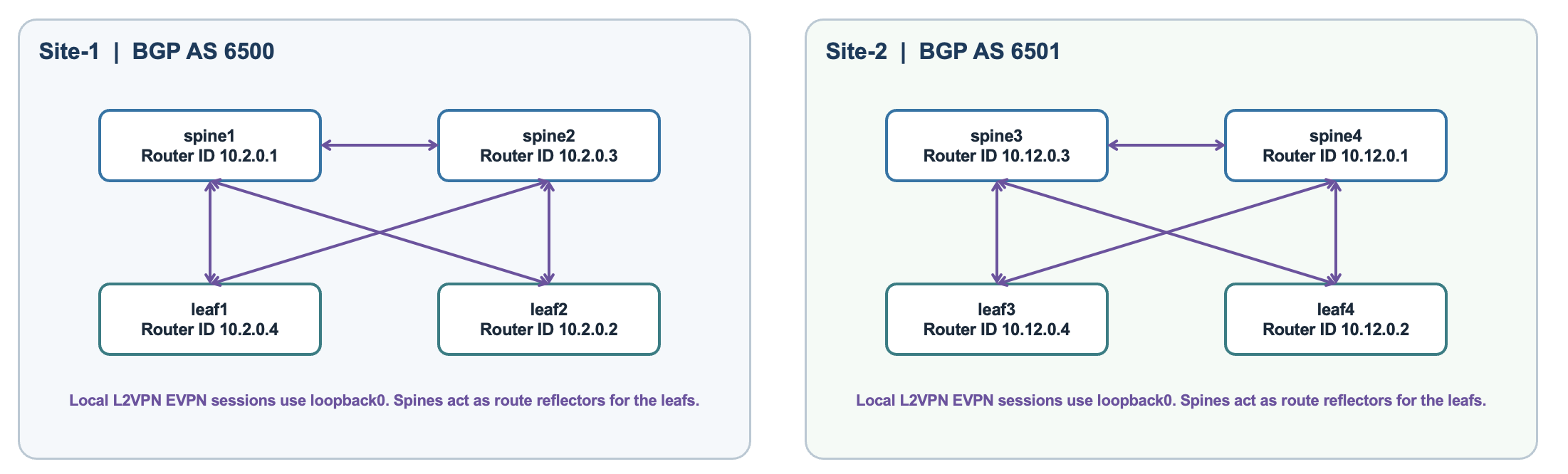
Figure 7. Leaf and spine BGP adjacency
Leaves establish iBGP EVPN sessions to both local spines using Loopback0. The spines act as route reflectors, passing EVPN routes between the leaves. The spines also exchange EVPN routes with each other. OSPF underlay reachability allows these loopback-based sessions to establish.
There is also a separate IPv4 iBGP session over the direct routed link between the local spines. For Spine-1 and Spine-2, this uses 10.4.0.5 and 10.4.0.6 on Ethernet1/1. Site 2 uses 10.14.0.5 and 10.14.0.6 on the corresponding local spine link.
5.2. BGP between the sites
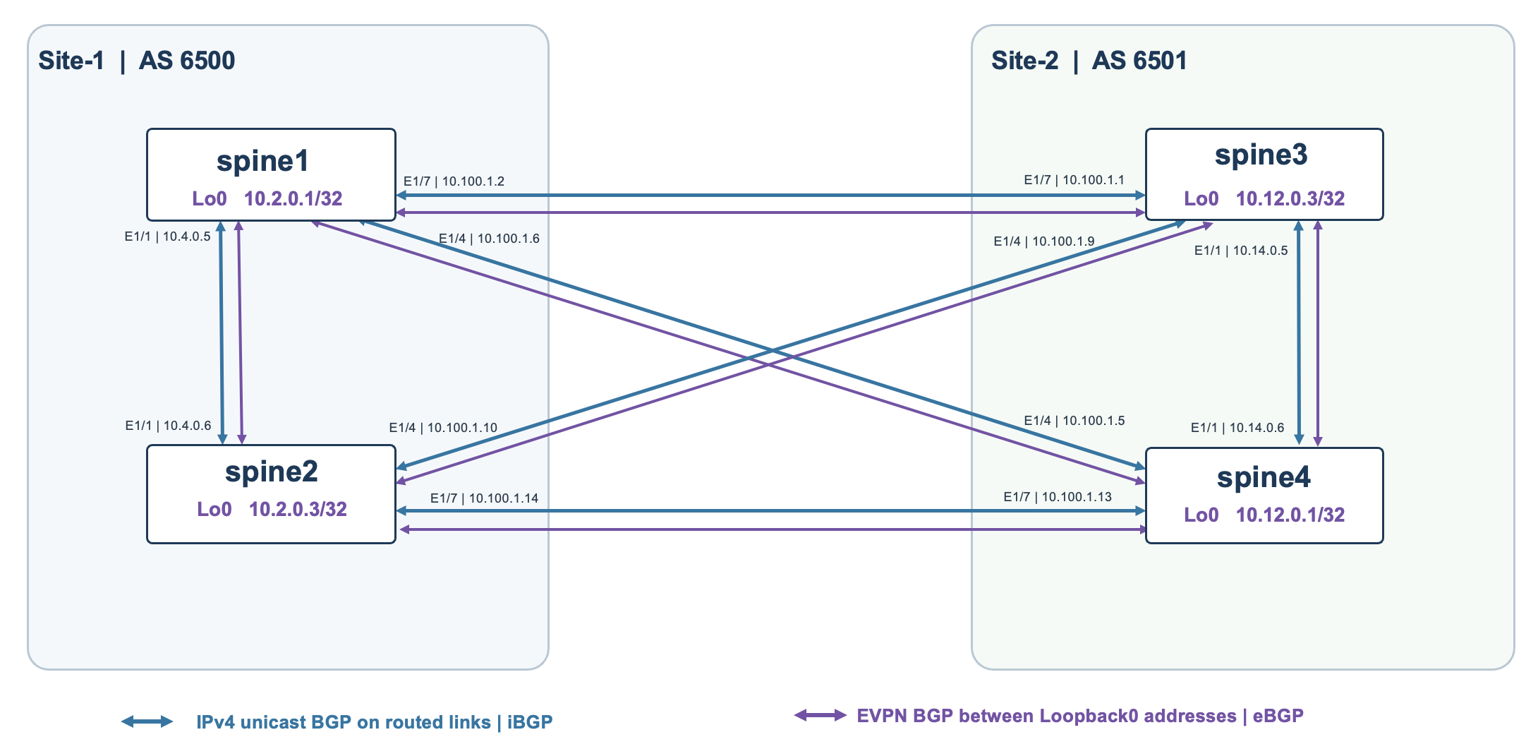
Figure 8. Spine BGP adjacency
Four /30 DCI links connect each Site-1 BGW to both Site-2 BGWs. IPv4 eBGP on those directly connected links exchanges transport reachability between AS 6500 and AS 6501. Separate EVPN eBGP sessions run between the remote BGWs’ Loopback0 addresses and use the available routed IP transport.
The existing Figure 6 legend incorrectly applies iBGP to every blue link and eBGP to every purple link. Both colors include local iBGP and inter-site eBGP relationships. The protocol and address family remain distinct from whether a peer is in the same AS.
EVPN BGP verification
spine1# show bgp l2vpn evpn summary
BGP router identifier 10.2.0.1, local AS number 6500
Neighbor        AS    Up/Down    State/PfxRcd
10.2.0.2        6500  09:46:57   15
10.2.0.3        6500  09:48:35    6
10.2.0.4        6500  09:46:46   15
10.12.0.1       6501  09:48:34   19
10.12.0.3       6501  09:48:34   19

spine3# show bgp l2vpn evpn summary
BGP router identifier 10.12.0.3, local AS number 6501
Neighbor        AS    Up/Down    State/PfxRcd
10.2.0.1        6500  10:24:31   20
10.2.0.3        6500  15:22:41   20
10.12.0.1       6501  1w5d        6
10.12.0.2       6501  1w5d       14
10.12.0.4       6501  1w5d       14
A numeric State/PfxRcd entry indicates an established session and gives the received prefix count. Spine-1 has three local peers—Leaf-2 10.2.0.2, Spine-2 10.2.0.3, and Leaf-1 10.2.0.4—and two remote BGWs, Spine-4 10.12.0.1 and Spine-3 10.12.0.3.
IPv4 BGP verification
spine1# show ip bgp neighbors
BGP neighbor is 10.4.0.6, remote AS 6500, ibgp link
  BGP version 4, remote router ID 10.2.0.3
  BGP state = Established
  Using Ethernet1/1 as update source for this peer
  Peer is directly attached, interface Ethernet1/1
BGP neighbor is 10.100.1.1, remote AS 6501, ebgp link
  BGP version 4, remote router ID 10.12.0.3
  BGP state = Established
  Using Ethernet1/7 as update source for this peer
  Peer is directly attached, interface Ethernet1/7
BGP neighbor is 10.100.1.5, remote AS 6501, ebgp link
  BGP version 4, remote router ID 10.12.0.1
  BGP state = Established
  Using Ethernet1/4 as update source for this peer
Spine-1’s local IPv4 peer is Spine-2 at 10.4.0.6 in AS 6500. Its two remote IPv4 peers are Spine-3 at 10.100.1.1 and Spine-4 at 10.100.1.5 in AS 6501. The output shows all three Established. These addresses are distinct from the Loopback0 addresses used by EVPN.
5.3. NVE interface and Multi Site VIP
nve1 is the switch’s logical VXLAN tunnel interface. source-interface loopback1 identifies the switch’s local VTEP. On the BGWs, multisite border-gateway interface loopback100 associates a second address with the Multi-Site function: a VIP shared by both BGWs at the same site.
spine1# show run
evpn multisite border-gateway 6500
  delay-restore time 300
interface loopback100
  description Multi-Site VIP loopback interface
  ip address 10.100.0.1/32 tag 54321
  ip router ospf UNDERLAY area 0.0.0.0
  ip pim sparse-mode
interface nve1
  no shutdown
  host-reachability protocol bgp
  source-interface loopback1
  multisite border-gateway interface loopback100
  member vni 30000
    multisite ingress-replication
    mcast-group 239.1.1.0
  member vni 30001
    multisite ingress-replication
    mcast-group 239.1.1.0
  member vni 30002
    multisite ingress-replication
    mcast-group 239.1.1.0
  member vni 30003
    multisite ingress-replication
    mcast-group 239.1.1.0
  member vni 50000 associate-vrf
  member vni 50001 associate-vrf
Spine-1 and Spine-2 use VIP 10.100.0.1/32. Spine-3 and Spine-4 use VIP 10.100.0.2/32. Remote VXLAN forwarding can reach a site through either available BGW. The tag 54321 makes these connected loopback routes eligible for the configured IPv4 BGP redistribution policy. A Multi-Site VIP is a tunnel destination and is separate from the VLAN 30 HSRP next-hop VIP 10.30.0.2.
The multicast group supplies local fabric BUM replication. BUM means broadcast, unknown unicast, and multicast traffic. multisite ingress-replication configures replication across the Multi-Site boundary. associate-vrf identifies a routed L3 VNI rather than a bridged VLAN VNI.
NVE and MAC route verification
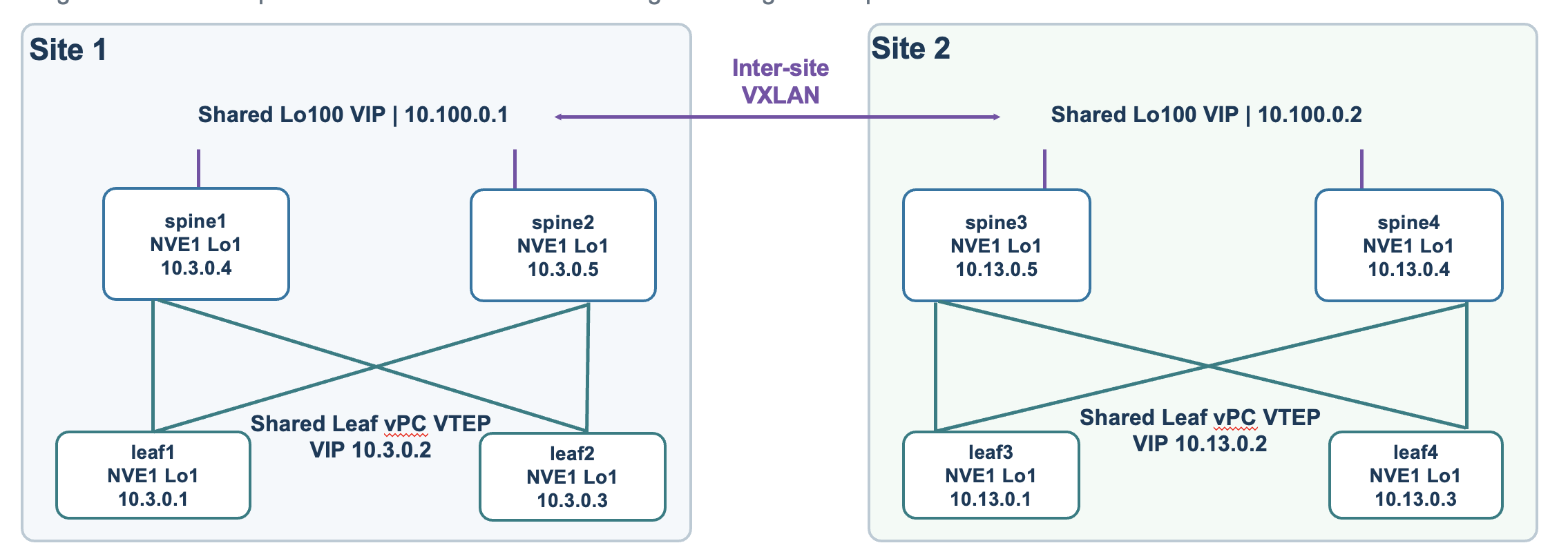
Figure 9. NVEs and VIPs
spine1# show nve interface nve1 detail
Interface: nve1, State: Up, encapsulation: VXLAN
 Host Learning Mode: Control-Plane
 Source-Interface: loopback1 (primary: 10.3.0.4, secondary: 0.0.0.0)
 Source Interface State: Up
 Multisite bgw-if: loopback100 (ip: 10.100.0.1, admin: Up, oper: Up)
spine1# show nve vni
Interface VNI      Multicast-group   State Mode Type [BD/VRF]      Flags
nve1      30000    239.1.1.0         Up    CP   L2 [99]            MS-IR
nve1      30001    239.1.1.0         Up    CP   L2 [20]            MS-IR
nve1      30002    239.1.1.0         Up    CP   L2 [10]            MS-IR
nve1      30003    239.1.1.0         Up    CP   L2 [30]            MS-IR
nve1      50000    n/a               Up    CP   L3 [protected]
nve1      50001    n/a               Up    CP   L3 [unprotected]
Up shows that the local NVE and VNI objects are operational at capture time. CP means control-plane learning through EVPN. MS-IR identifies Multi-Site ingress replication. The output directly distinguishes the bridged VLAN VNIs from the routed VRF VNIs.
spine1# show l2route evpn mac all
Topology    Mac Address    Prod   Flags              Seq No     Next-Hops
10          cced.4dd4.1011 BGP    Rcv                0          10.3.0.2 (Label: 30002)
10          cced.4dd4.1012 BGP    Rcv                0          10.100.0.2 (Label: 30002)(Flags: RS)
10          cced.4dd4.5000 BGP    Rcv                0          10.3.0.2 (Label: 30002)
30          cced.4dd4.3012 BGP    Rcv                0          10.100.0.2 (Label: 30003)(Flags: RS)
Spine-1 learns the Site-1 VLAN 10 MAC through local VTEP 10.3.0.2 and the Site-2 MAC through remote Multi-Site VIP 10.100.0.2. RS marks a remote-site route. The global MAC row points to the local VTEP. This is forwarding-table evidence for local gateway learning and remote site-specific MAC reachability, rather than a per-flow packet trace.
spine1# show nve peers
Interface Peer-IP       State LearnType Uptime   Router-Mac
--------- ------------- ----- --------- -------- -----------------
nve1      10.3.0.1      Up    CP        12:42:15 9c54.1651.6529
nve1      10.3.0.2      Up    CP        12:42:15 0200.0a03.0002
nve1      10.3.0.3      Up    CP        12:42:15 9c54.1651.53f7
nve1      10.13.0.4     Up    CP        12:41:57 9c54.1651.4ddd
nve1      10.13.0.5     Up    CP        12:41:20 f4ee.31a3.d857
nve1      10.100.0.2    Up    CP        12:41:57 0200.0a64.0002


leaf1# show nve peers
Interface Peer-IP                                 State LearnType Uptime   Router-Mac
nve1      10.100.0.1                              Up    CP        12:45:00 n/a
leaf1# show nve vni
Interface VNI      Multicast-group   State Mode Type [BD/VRF]      Flags
nve1      40000    239.1.1.0         Up    CP   L2 [40]
The Leaf-1 peer at 10.100.0.1 is its own site’s BGW VIP. The leaf reaches the Multi-Site boundary through its local BGWs; the BGWs use remote-site reachability for the inter-site step.
Protected prefix advertisement into EVPN
The supplied leaf configuration originates the protected /16 prefixes under BGP in VRF unprotected using network statements and advertises them into EVPN.
leaf1# show run
router bgp 6500
  vrf unprotected
    address-family ipv4 unicast
      network 10.10.0.0/16
      network 10.20.0.0/16
      advertise l2vpn evpn
      redistribute direct route-map fabric-rmap-redist-subnet
      maximum-paths ibgp 2
6. Traffic flow
6.1. Traffic between protected VLANs – Forward Traffic
A VLAN 10 server uses gateway 10.10.0.1 to reach VLAN 20. The leaves do not route directly between these server VLANs. The firewall inspects and routes the packet onto VLAN 20, whose gateway is 10.20.0.1. Traffic between hosts in the same VLAN normally remains Layer 2; VXLAN can carry that traffic between sites without firewall inspection.
Let us take an example of traffic flow of Server A in VLAN 10 → Server B in VLAN 20.
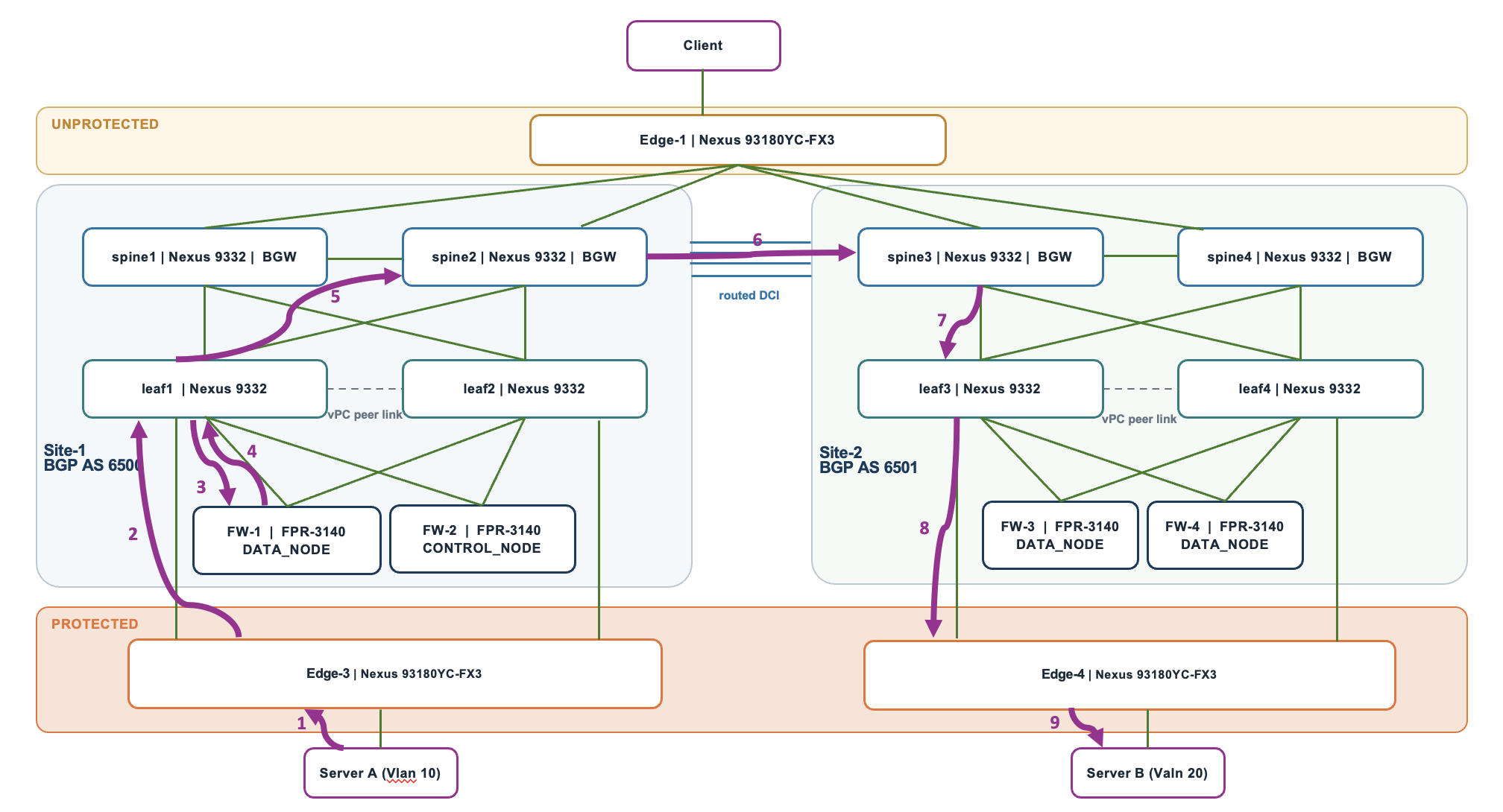
Figure 10. Forward traffic between protected VLANs
-
Server A → Edge-3
Server A identifies Server B as being in a different subnet and sends the packet to its default gateway, 10.10.0.1, on the firewall cluster. The Ethernet frame carries the firewall gateway’s destination MAC address and enters Edge-3 in VLAN 10.
-
Edge-3 → Leaf1
Edge-3 forwards the frame to Leaf1 over the protected network connection. Edge-3 operates at Layer 2, so the frame remains in VLAN 10.
-
Leaf1 → FW-1
Leaf1 forwards the VLAN 10 frame to FW-1’s inside_10 interface. Leaf1 performs Layer 2 forwarding here; the firewall is Server A’s gateway and the first device to route the packet.
-
FW-1 → Leaf1
FW-1 inspects the connection and routes the packet using its directly connected 10.20.0.0/16 route through inside_20. It sends a new Ethernet frame toward Server B’s MAC address, returning the traffic to Leaf1 in VLAN 20.
-
Leaf1 → Spine2
EVPN provides Leaf1 with reachability information for Server B’s MAC address in Site 2. Leaf1 encapsulates the VLAN 20 frame in VXLAN using L2 VNI 30001 and forwards it to Spine2, the local border gateway selected in this example.
-
Spine2 → Spine3 across the routed DCI
Spine2 removes the local VXLAN encapsulation and re-encapsulates the frame for inter-site transport, retaining VNI 30001. The destination is Site 2’s Multi-Site VIP, 10.100.0.2, which the routed inter-site network delivers to Spine3 in the illustrated path.
-
Spine3 → Leaf3
Spine3 removes the inter-site VXLAN encapsulation. Using the destination’s EVPN reachability information, it re-encapsulates the frame in VXLAN toward the Site 2 leaf endpoint, retaining VNI 30001.
-
Leaf3 → Edge-4
Leaf3 removes the VXLAN encapsulation and forwards the original inner Ethernet frame toward Edge-4 in VLAN 20. This is Layer 2 forwarding; Leaf3 does not route the packet again.
-
Edge-4 → Server B
Edge-4 forwards the VLAN 20 frame to the port connected to Server B. Server B receives the packet sent by Server A.
6.2. Traffic between protected VLANs – Return traffic through the cluster control link
In this example, FW-1 in Site 1 owns the connection, but Server B’s reply reaches FW-3 in Site 2. FW-3 forwards the reply across the cluster control link (CCL) to FW-1 for processing.
Purple arrows show server traffic; orange arrows show CCL forwarding.
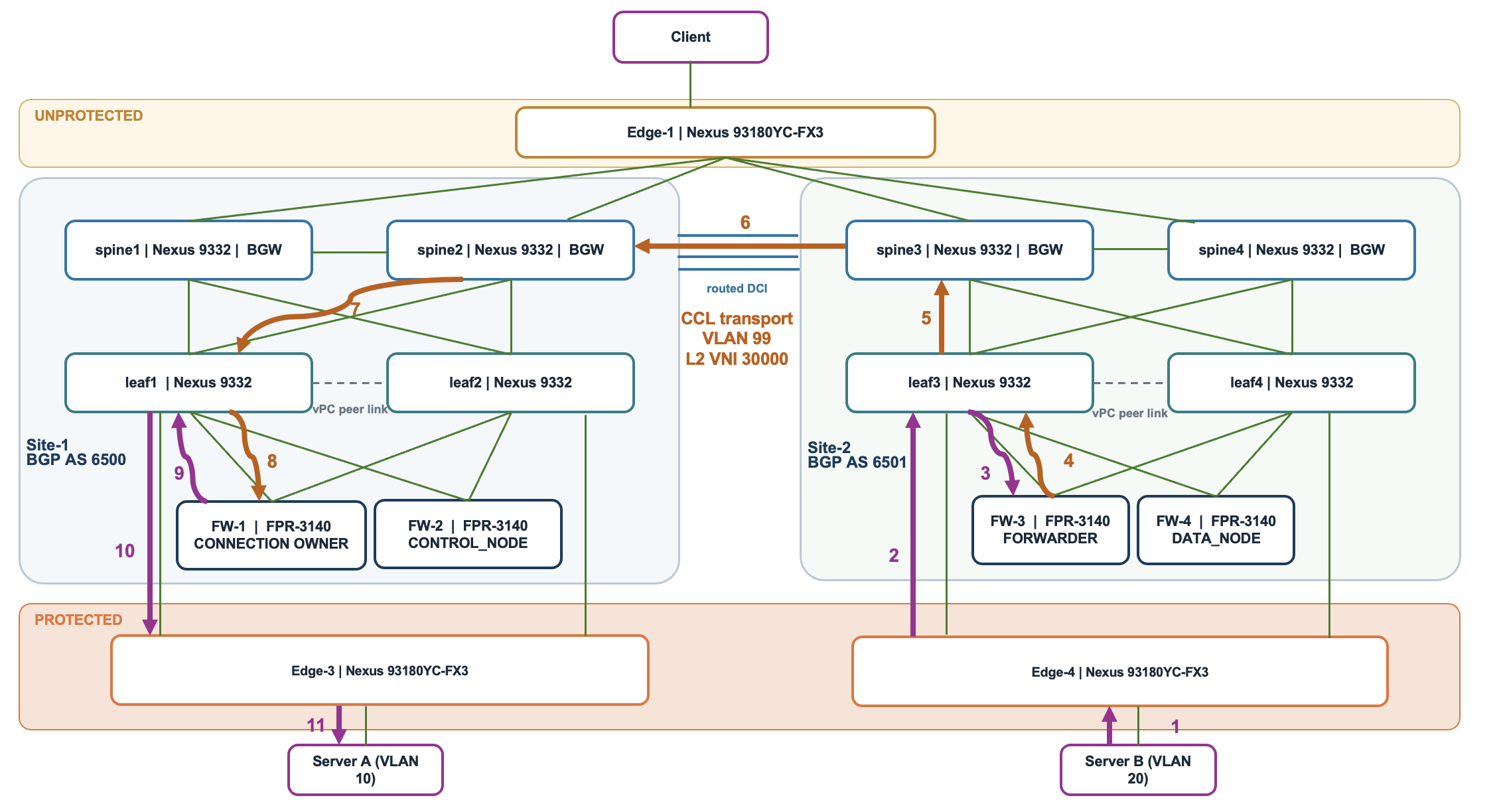
Figure 11. Return traffic between protected VLANs
-
Server B → Edge-4
Server B sends its reply toward its firewall gateway, 10.20.0.1. The frame enters Edge-4 in VLAN 20.
-
Edge-4 → Leaf3
Edge-4 forwards the VLAN 20 frame to Leaf3 at Layer 2.
-
Leaf3 → FW-3
Leaf3 forwards the frame to FW-3’s inside_20 interface. FW-3 determines that FW-1 owns the connection and acts as a forwarder.
-
FW-3 → Leaf3 over the CCL
FW-3 sends the reply toward FW-1 through its dedicated CCL interface, Port-channel48. The leaf-facing connection carries VLAN 99, with the original reply packet inside the cluster forwarding encapsulation.
-
Leaf3 → Spine3
Leaf3 encapsulates the CCL frame in VXLAN using L2 VNI 30000 and forwards it to the local border gateway, Spine3.
-
Spine3 → Spine2 across the DCI
Spine3 re-encapsulates the frame toward Site 1’s Multi-Site VIP, 10.100.0.1, retaining VNI 30000. In the illustrated path, Spine2 receives it.
-
Spine2 → Leaf1
Spine2 removes the inter-site VXLAN encapsulation and re-encapsulates the frame toward the Site 1 leaf endpoint serving FW-1, retaining VNI 30000.
-
Leaf1 → FW-1 over the CCL
Leaf1 removes the VXLAN encapsulation and forwards the CCL frame in VLAN 99 to FW-1’s Port-channel48. FW-1 receives the reply and processes it against the existing connection state.
-
FW-1 → Leaf1
FW-1 routes the reply toward Server A through inside_10, sending a new Ethernet frame in VLAN 10.
-
Leaf1 → Edge-3
Leaf1 forwards the VLAN 10 frame to Edge-3 at Layer 2.
-
Edge-3 → Server A
Edge-3 forwards the reply to Server A’s connected port in VLAN 10.
The inter-site hop carries the forwarded reply through the CCL using VLAN 99 / VNI 30000. FW-1 remains the connection owner.
6.3. Traffic from unprotected network to a protected VLAN
Traffic from an unprotected client passes through the edge, spine and leaf switches to the firewall. The firewall inspects the connection and, if permitted, routes the packet into VLAN 10. The leaf and protected edge switch then forward it to the server.
Let us take an example of traffic flow of traffic flow from an unprotected client → Server A in VLAN 10.
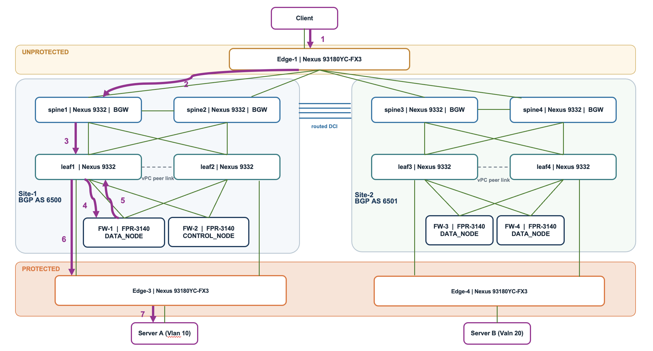
Figure 12. Traffic from unprotected network to protected VLAN
-
Client → Edge-1
The client sends the packet to its default gateway, 10.101.0.1, on Edge-1’s VLAN 101 SVI. Edge-1 is the client’s first routing hop.
-
Edge-1 → Spine1
Edge-1 uses its configured static route for 10.10.0.0/16. In this example, it selects next hop 10.33.0.1, Spine1’s address on the routed connection. The packet enters Spine1’s unprotected VRF.
-
Spine1 → Leaf1
Spine1 uses the protected subnet route advertised by the leaves through BGP EVPN. It selects Leaf1 and forwards the packet through VXLAN using L3 VNI 50001, which identifies the unprotected VRF.
-
Leaf1 → FW-1
Leaf1 removes the VXLAN encapsulation and looks up the destination. Its route to 10.10.0.0/16, learned from the firewall through OSPF on VLAN 30, points toward the firewall. Leaf1 forwards the packet in VLAN 30 to the cluster’s outside address, 10.30.0.1.
-
FW-1 → Leaf1
FW-1 inspects the connection and routes the permitted packet through inside_10, using its directly connected route for 10.10.0.0/16. It sends a new Ethernet frame toward Server A’s MAC address in VLAN 10.
-
Leaf1 → Edge-3
Leaf1 forwards the VLAN 10 frame to Edge-3 at Layer 2. The firewall has already performed the routing into the protected subnet.
-
Edge-3 → Server A
Edge-3 forwards the frame to Server A’s connected port in VLAN 10, completing delivery.
7. Failure scenarios and traffic recovery
The following scenarios explain how traffic uses surviving connections after a failure. In the accompanying diagrams, grey dashed arrows show the complete original path, purple arrows show recovered data forwarding, and orange arrows show forwarding over the cluster control link (CCL). A red cross identifies the failed component. Each diagram illustrates one selected forwarding path.
7.1. Single firewall data-link failure
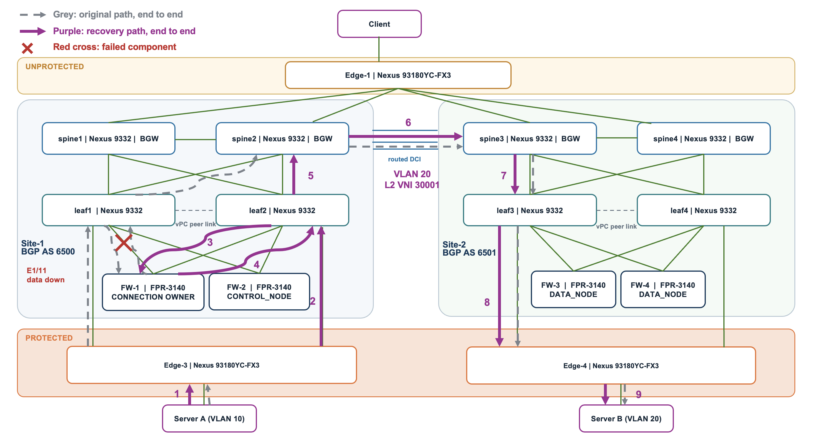
Figure 13. Single firewall data-link failure
If the data link between Leaf1 Ethernet1/11 and FW-1 fails, FW-1 remains connected through Leaf2. Port-channel and vPC forwarding use the surviving attachment. Since FW-1 itself remains active, it can retain ownership of the illustrated connection.
Originally, Server A’s VLAN 10 traffic reaches FW-1 through Edge-3 and Leaf1. After the failure, Edge-3 forwards through Leaf2 to FW-1. The firewall inspects and routes the packet onto VLAN 20, then returns it through Leaf2. VXLAN carries the packet through Spine2 and Spine3 to Leaf3, Edge-4 and Server B.
Repairing the failed link allows it to rejoin the port-channel. The restored attachment becomes available for forwarding, although an existing connection does not necessarily move back to its original link.
7.2. Leaf data port-channel failure
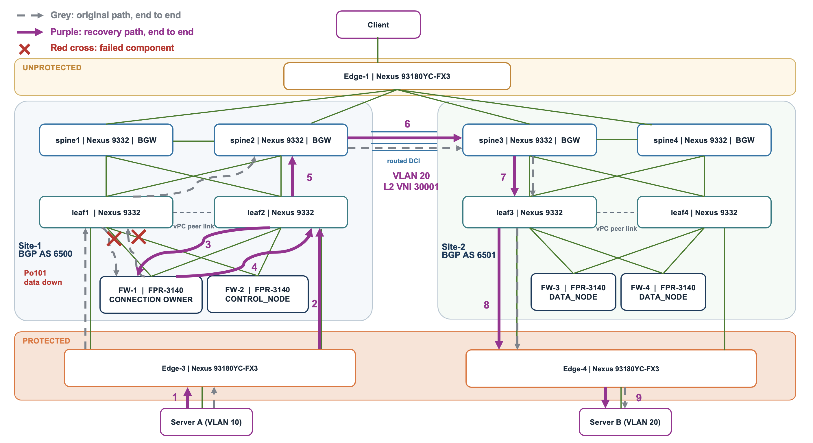
Figure 14. Leaf data port-channel failure
If Port-channel101 on Leaf1 fails, its local data attachments to both FW-1 and FW-2 become unavailable. Both firewalls retain their data connections through Leaf2. Their dedicated CCL attachments are separate from the failed data port-channel.
For the illustrated VLAN 10 to VLAN 20 connection, traffic moves from Leaf1 to Leaf2. Server A sends through Edge-3 and Leaf2 to FW-1. After inspection and routing, FW-1 sends the VLAN 20 packet through Leaf2, Spine2, Spine3, Leaf3 and Edge-4 to Server B.
Recovery requires restoring Leaf1’s Po101 and its member interfaces, then confirming port-channel and vPC operation. Once forwarding converges, the restored attachments can carry traffic again. This failure does not require a connection-owner change while FW-1 remains active and reachable.
7.3. Single CCL attachment failure
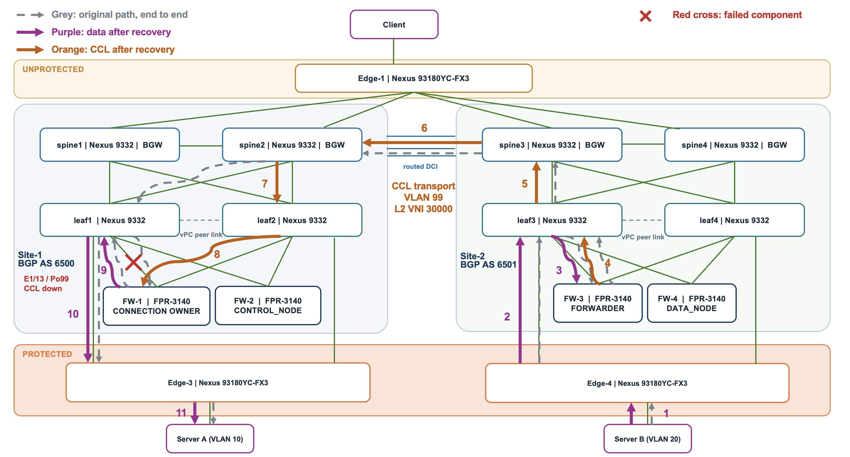
Figure 15. Single CCL attachment failure
If FW-1’s CCL attachment through Leaf1 Ethernet1/13 in Port-channel99 fails, its dedicated CCL attachment through Leaf2 remains available. Cluster forwarding and state traffic can use that surviving attachment. FW-1’s data connection through Leaf1 remains usable.
Consider a reply from Server B that reaches FW-3 in Site 2 while FW-1 in Site 1 owns the connection. FW-3 forwards the packet toward FW-1 over the CCL. Leaf3 carries the CCL frame in VLAN 99 using VXLAN L2 VNI 30000, through Spine3 and Spine2.
Originally, the packet reaches FW-1 through Leaf1. After the attachment failure, delivery uses Leaf2. FW-1 processes the forwarded reply and sends it onto VLAN 10 through its intact Leaf1 data connection. Leaf1 and Edge-3 then deliver it to Server A.
Repair the failed CCL attachment and confirm that it rejoins its port-channel. This recovery depends on the surviving attachment providing end-to-end CCL reachability.
7.4. Complete leaf-switch failure
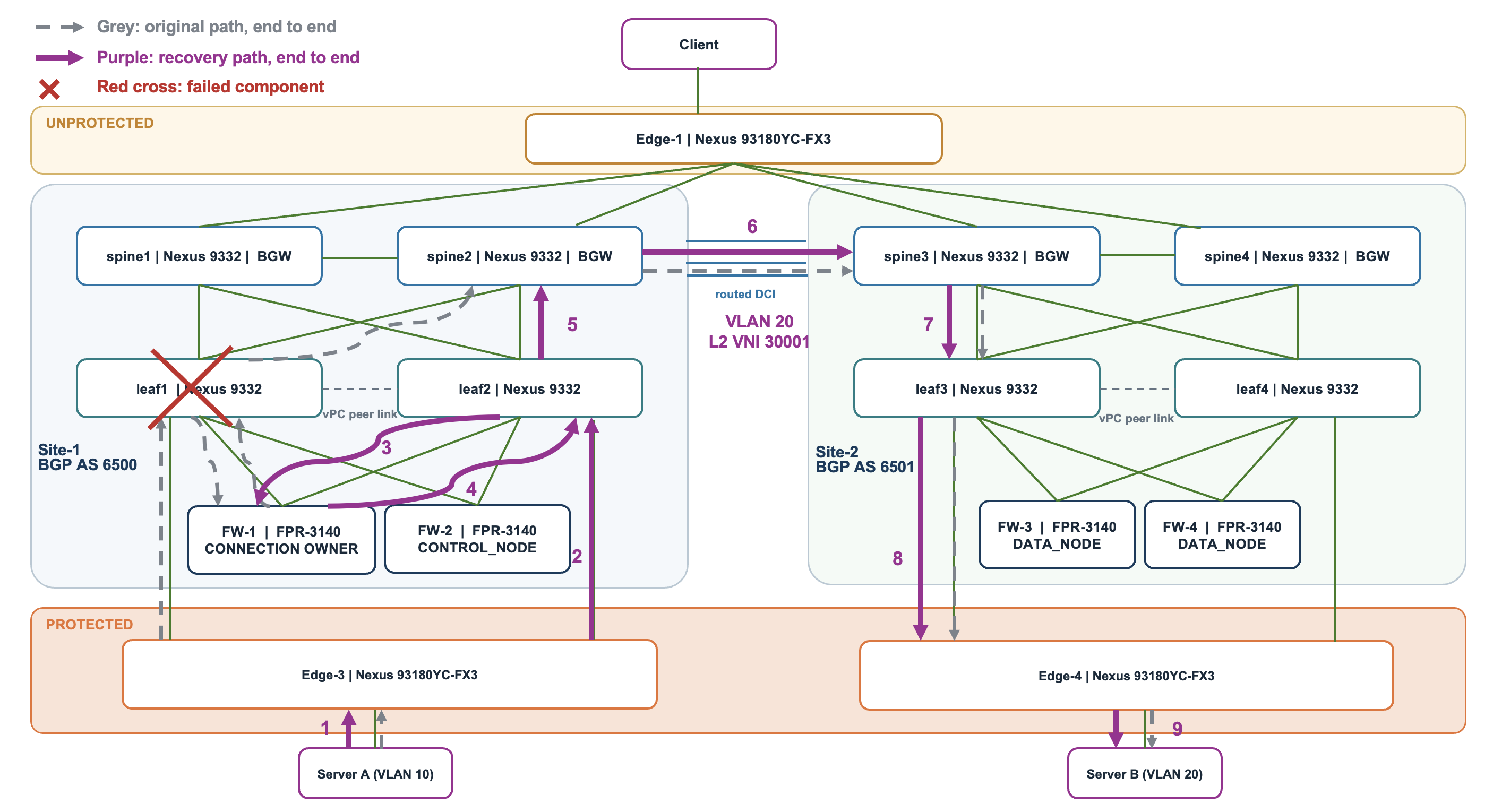
Figure 16. Complete leaf-switch failure
If Leaf1 fails or reloads, its fabric links, protected-edge connection, firewall data attachments and dedicated CCL attachments become unavailable. Leaf2 provides the surviving connections for Edge-3 and the local firewalls. The firewalls can remain active while their required data and CCL connectivity remains available.
For the illustrated flow, Server A sends VLAN 10 traffic through Edge-3 and Leaf2 to FW-1. FW-1 inspects and routes onto VLAN 20, then returns the packet through Leaf2. VXLAN transports it through Spine2 and Spine3 to Leaf3, Edge-4 and Server B. The dedicated CCL also uses the surviving Leaf2 attachment when needed.
After Leaf1 returns, its vPC, port-channels, underlay routing, EVPN and NVE operation must recover before its paths are treated as available. Traffic can be interrupted while forwarding converges.
7.5. Control-node failure
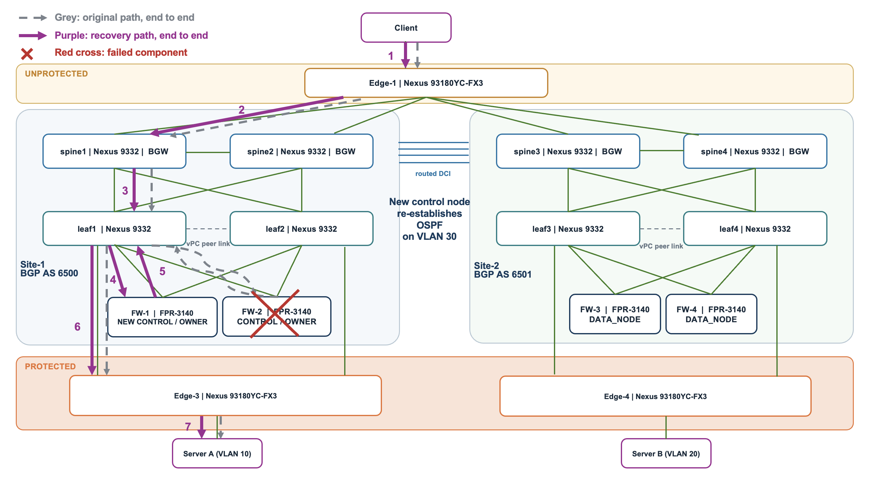
Figure 17. Control-node failure
If the control node fails, the surviving cluster members elect a new control node. In this spanned deployment, OSPF runs on the control node. The new control node must re-establish its OSPF adjacencies with the leaves on VLAN 30 so that the protected prefixes can be advertised again. Recovery therefore includes both cluster election and routing convergence.
The diagram assumes FW-2 was the control node and also owned the illustrated client connection. FW-1 is elected as the new control node and takes over that connection using available replicated state.
After recovery, client traffic passes through Edge-1 and Spine1. Spine1 sends routed VXLAN traffic toward Leaf1 using the unprotected VRF’s L3 VNI 50001. Leaf1 delivers the packet to FW-1 on outside VLAN 30. FW-1 inspects and routes it onto VLAN 10, then Leaf1 and Edge-3 deliver it to Server A.
The control-node and connection-owner roles are separate. Connections owned by other surviving members can retain their owners. Affected connections without usable backup state may need to be re-established. When the failed firewall returns, it rejoins the cluster without an assumed automatic transfer of the roles back to it. In this case, when the control node comes back up, it would join as a data node and not resume as the control node.
7.6. Complete inter-site CCL partition
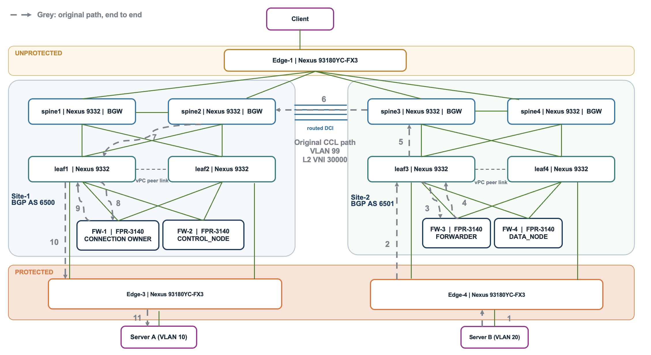
Figure 18. Original flow before inter-site CCL partition
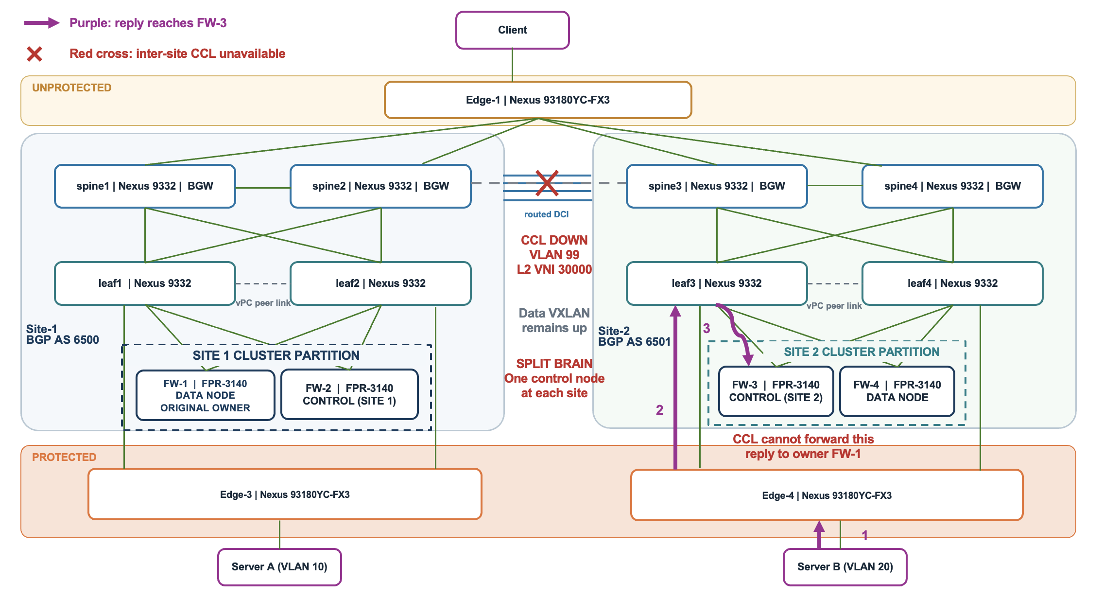
Figure 19. Flow after inter-site CCL partition
This scenario assumes that inter-site CCL connectivity fails while local CCL connectivity within each site and data VXLAN connectivity remain operational. After failure detection, the four-member cluster can split into two independent two-member groups, each with its own control node. This condition is called split brain of a cluster.
-
Site 1: FW-1 and FW-2 remain together, with FW-2 retaining its existing control role.
-
Site 2: FW-3 and FW-4 form a separate group. With both healthy, FW-3 becomes control because its configured priority, 3, is higher than FW-4’s priority, 4; a lower number means higher priority.
Server B’s reply follows Server B → Edge-4 → Leaf3 → FW-3. Before the partition, FW-3 forwards this reply over the CCL to its connection owner, FW-1 at Site 1. During the partition, that forwarding path is unavailable. FW-3 becoming control does not automatically make it the connection owner. Consequently, the illustrated existing connection may fail.
Traffic that can be handled entirely within a site may continue. Operational data VXLAN connectivity alone does not restore cross-site cluster state exchange or CCL owner forwarding.
Recovery can be done by restoring inter-site CCL connectivity. The two groups reconcile into one cluster, with the higher-priority control node retaining the control role. Affected connections may need to be re-established.
8. Configuration reference
NOTE: These are focused excerpts rather than complete device configurations.
8.1. Secure Firewall members
FW-1#show run
interface Port-channel10.10
 mac-address cced.4dd4.5000
 mac-address cced.4dd4.1011 site-id 1 site-ip 10.10.0.5
 mac-address cced.4dd4.1012 site-id 2 site-ip 10.10.0.6
 vlan 10
 nameif inside_10
 ip address 10.10.0.1 255.255.0.0
interface Port-channel10.20
 mac-address cced.4dd4.5000
 mac-address cced.4dd4.2011 site-id 1 site-ip 10.20.0.5
 mac-address cced.4dd4.2012 site-id 2 site-ip 10.20.0.6
 vlan 20
 nameif inside_20
 ip address 10.20.0.1 255.255.0.0
interface Port-channel10.30
 mac-address cced.4dd4.5000
 mac-address cced.4dd4.3011 site-id 1 site-ip 10.30.0.5
 mac-address cced.4dd4.3012 site-id 2 site-ip 10.30.0.6
 vlan 30
 nameif outside
 ip address 10.30.0.1 255.255.255.0
 ospf hello-interval 1
 ospf dead-interval 3
 ospf bfd disable
interface Port-channel48
 description Clustering Interface
cluster group 3140-Cluster
 local-unit FW-1
 cluster-interface Port-channel48 ip 99.99.99.1 255.255.255.224
 site-id 1
 site-redundancy
 enable
 director-localization
The firewall uses Po10 for data and Po48 for CCL. Each member has its own local-unit, site ID, and CCL address.
8.2. Leaf switches
leaf1#show run
vlan 10
  vn-segment 30002
vlan 20
  vn-segment 30001
vlan 30
  vn-segment 30003
vlan 99
  vn-segment 30000
vlan 2001
  name unprotected
  vn-segment 50001
vrf context unprotected
  vni 50001
  rd auto
  address-family ipv4 unicast
    route-target both auto evpn
port-channel load-balance src-dst ip-l4port symmetric
vpc domain 1
  peer-switch
  peer-keepalive destination 198.18.158.19 source 198.18.158.17
  peer-gateway
  layer3 peer-router
interface port-channel500
  switchport mode trunk
  vpc peer-link
interface port-channel99
  switchport
  switchport access vlan 99
  vpc 99
interface port-channel100
  switchport
  switchport access vlan 99
  vpc 100
interface port-channel101
  switchport mode trunk
  switchport trunk allowed vlan 10,20,30
  vpc 101
interface port-channel102
  switchport mode trunk
  switchport trunk allowed vlan 10,20
  vpc 102
interface nve1
  no shutdown
  host-reachability protocol bgp
  source-interface loopback1
  member vni 30000
    mcast-group 239.1.1.0
  member vni 30001
    mcast-group 239.1.1.0
  member vni 30002
    mcast-group 239.1.1.0
  member vni 30003
    mcast-group 239.1.1.0
  member vni 50000 associate-vrf
  member vni 50001 associate-vrf
Leaf-1 routed underlay, VLAN 30 HSRP, and both local EVPN peers.
leaf1#show run
interface Ethernet1/3
  description connected-to-spine1-Ethernet1/5
  ip address 10.4.0.13/30
  ip ospf network point-to-point
  ip router ospf UNDERLAY area 0.0.0.0
interface Ethernet1/4
  description connected-to-spine2-Ethernet1/5
  ip address 10.4.0.17/30
  ip ospf network point-to-point
  ip router ospf UNDERLAY area 0.0.0.0
interface Vlan3600
  description VPC-Peer-Link SVI
  ip address 10.4.0.1/30
  ip ospf network point-to-point
  ip router ospf UNDERLAY area 0.0.0.0
interface Vlan30
  no shutdown
  mtu 9000
  vrf member unprotected
  no ip redirects
  ip address 10.30.0.254/24 tag 12345
  no ipv6 redirects
  ip ospf dead-interval 3
  ip ospf hello-interval 1
  ip router ospf 1 area 0.0.0.0
  hsrp version 2
  hsrp 30
    priority 110
    ip 10.30.0.2
router ospf 1
  vrf unprotected
    router-id 1.1.1.1
router ospf UNDERLAY
  router-id 10.2.0.4
router bgp 6500
  router-id 10.2.0.4
  neighbor 10.2.0.1
    remote-as 6500
    description to-spine1
    update-source loopback0
    address-family l2vpn evpn
      send-community
      send-community extended
  neighbor 10.2.0.3
    remote-as 6500
    description to-spine2
    update-source loopback0
    address-family l2vpn evpn
      send-community
      send-community extended
Switch Po99 and Po100 attach CCL VLAN 99; Po101 attaches firewall data VLANs 10/20/30; Po102 attaches the protected edge; Po500 is the vPC peer link. The VTEP source is Loopback1, while BGP uses Loopback0.
8.3. Spine and Multi Site border gateways
spine1#show run
evpn multisite border-gateway 6500
  delay-restore time 300
interface Ethernet1/5
  description connected-to-leaf1-Ethernet1/3
  ip address 10.4.0.14/30
  ip ospf network point-to-point
  ip router ospf UNDERLAY area 0.0.0.0
  evpn multisite fabric-tracking
interface Ethernet1/7
  description connected-to-spine3-Ethernet1/7
  ip address 10.100.1.2/30
  evpn multisite dci-tracking
interface loopback100
  description Multi-Site VIP loopback interface
  ip address 10.100.0.1/32 tag 54321
Fabric-tracking monitors the BGW’s local fabric attachment. dci-tracking monitors its DCI attachment. Keep the global-MAC EVPN route filter and HSRP VLAN filter from Section 3 on every BGW.
spine1#show run
router bgp 6500
  router-id 10.2.0.1
  cluster-id 6500
  neighbor 10.2.0.2
    remote-as 6500
    update-source loopback0
    address-family l2vpn evpn
      send-community
      send-community extended
      route-reflector-client
  neighbor 10.2.0.3
    remote-as 6500
    update-source loopback0
    address-family l2vpn evpn
      send-community
      send-community extended
  neighbor 10.2.0.4
    remote-as 6500
    update-source loopback0
    address-family l2vpn evpn
      send-community
      send-community extended
      route-reflector-client
router bgp 6500
  neighbor 10.12.0.1
    remote-as 6501
    description multi-site overlay session to spine4
    update-source loopback0
    ebgp-multihop 5
    peer-type fabric-external
    address-family l2vpn evpn
      send-community
      send-community extended
      route-map Global-mac-filter in
      rewrite-evpn-rt-asn
  neighbor 10.12.0.3
    remote-as 6501
    description multi-site overlay session to spine3
    update-source loopback0
    ebgp-multihop 5
    peer-type fabric-external
    address-family l2vpn evpn
      send-community
      send-community extended
      route-map Global-mac-filter in
      rewrite-evpn-rt-asn
router bgp 6500
  neighbor 10.4.0.6
    remote-as 6500
    update-source Ethernet1/1
    address-family ipv4 unicast
      next-hop-self
  neighbor 10.100.1.1
    remote-as 6501
    update-source Ethernet1/7
    address-family ipv4 unicast
      next-hop-self
  neighbor 10.100.1.5
    remote-as 6501
    update-source Ethernet1/4
    address-family ipv4 unicast
      next-hop-self
ip access-list hsrp-hello-filter
  10 permit udp any 224.0.0.2/32 eq 1985
  20 permit udp any 224.0.0.102/32 eq 1985
ip access-list permit-all
  10 permit ip any any
vlan access-map hsrp-hello-filter 10
  match ip address hsrp-hello-filter
  action drop
vlan access-map hsrp-hello-filter 20
  match ip address permit-all
  action forward
vlan filter hsrp-hello-filter vlan-list 30
mac-list Global-mac-filter seq 15 permit cced.4dd4.5000 ffff.ffff.ffff
route-map Global-mac-filter deny 10
  match mac-list Global-mac-filter
route-map Global-mac-filter permit 20
router bgp 6500
  neighbor 10.12.0.1
    address-family l2vpn evpn
      route-map Global-mac-filter in
  neighbor 10.12.0.3
    address-family l2vpn evpn
      route-map Global-mac-filter in
8.4. Active unprotected edge
Edge-1 provides the VLAN 101 gateway and connects to all four BGWs. The common edge is outside the two site boundaries.
Edge1#show run
interface Vlan101
  no shutdown
  ip address 10.101.0.1/16
  ip router ospf 1 area 0.0.0.0
router ospf 1
  router-id 1.1.1.1
interface Ethernet1/49.2
  mtu 9216
  encapsulation dot1q 2
  ip address 10.33.0.2/30
  ip ospf network point-to-point
  ip router ospf 1 area 0.0.0.0
  no shutdown
interface Ethernet1/50.2
  mtu 9216
  encapsulation dot1q 2
  ip address 10.33.0.10/30
  ip ospf network point-to-point
  ip router ospf 1 area 0.0.0.0
  no shutdown
interface Ethernet1/51.2
  mtu 9216
  encapsulation dot1q 2
  ip address 10.34.0.2/30
  ip ospf network point-to-point
  ip router ospf 1 area 0.0.0.0
  no shutdown
interface Ethernet1/52.2
  mtu 9216
  encapsulation dot1q 2
  ip address 10.34.0.10/30
  ip ospf network point-to-point
  ip router ospf 1 area 0.0.0.0
  no shutdown
The four remote BGW addresses are 10.33.0.1, 10.33.0.9, 10.34.0.1, and 10.34.0.9. The corresponding BGW interfaces are Spine-1/2 Ethernet1/2.2 and Spine-3/4 Ethernet1/1.2.
8.5. Protected edge switches
The protected edges use Layer 2 VLANs and trunk port-channels to the leaves.
Edge3#show run
interface port-channel102
  switchport
  switchport mode trunk
interface Ethernet1/49
  switchport
  switchport mode trunk
  channel-group 102 mode active
  no shutdown
interface Ethernet1/50
  switchport
  switchport mode trunk
  channel-group 102 mode active
  no shutdown
interface Ethernet1/53
  switchport
  switchport mode trunk
  switchport trunk allowed vlan 10
  spanning-tree port type edge trunk
  mtu 9216
  no shutdown
Port-channel102 and its members carry the Layer 2 uplink. Ethernet1/53 is the test-host attachment in this excerpt. The firewall remains the first Layer 3 hop for the protected server VLANs.
9. Glossary of architecture-specific terms
| Term | Meaning |
|---|---|
| Spanned interface mode | Firewall interfaces across cluster members form a shared logical EtherChannel. |
| Split-spanned EtherChannel | An inter-site arrangement with separate local switch-side bundles at each site. |
| Control node | The elected member coordinating cluster configuration and centralized functions. It also processes traffic. |
| Data node | A member processing traffic without holding the control role. |
| Connection owner | The member processing a particular connection and maintaining its state. |
| Director | The member tracking a connection’s owner and answering ownership queries. |
| Backup owner | A member storing replicated connection state to support recovery after failure. |
| Forwarder | A member forwarding received packets to their connection owner. |
| Cluster control link (CCL) | Carries cluster coordination, replicated state, and packets forwarded between members. |
| Director localization | Keeps director and backup functions at the owner’s site for supported flows. |
| Site redundancy | Provides connection-state backup at another site to improve resilience to site failure. |
| Split brain | Isolated groups of cluster members operate independently, each with its own control node, after losing CCL communication. |
| Global and site-specific firewall identities | Global IP/MAC addresses identify the shared firewall interfaces. Site-specific IP/MAC pairs identify each site’s outgoing Ethernet and ARP behavior. |
| Border gateway (BGW) | Connects a local VXLAN fabric to other sites. The spines perform this role here. |
| Multi-Site VIP | A tunnel address shared by the BGWs at a site, allowing remote VXLAN traffic to reach that site. |
| VTEP / NVE interface | A VTEP adds or removes VXLAN encapsulation. The logical nve1 interface represents that tunnel function on the switch. |
| Layer 2 VNI / Layer 3 VNI | A Layer 2 VNI identifies a bridged segment; a Layer 3 VNI identifies a VRF for routed VXLAN forwarding. |
Updated about 1 hour ago